light YAMAHA RHINO 700 2012 Owner's Manual
[x] Cancel search | Manufacturer: YAMAHA, Model Year: 2012, Model line: RHINO 700, Model: YAMAHA RHINO 700 2012Pages: 492, PDF Size: 12.99 MB
Page 324 of 492
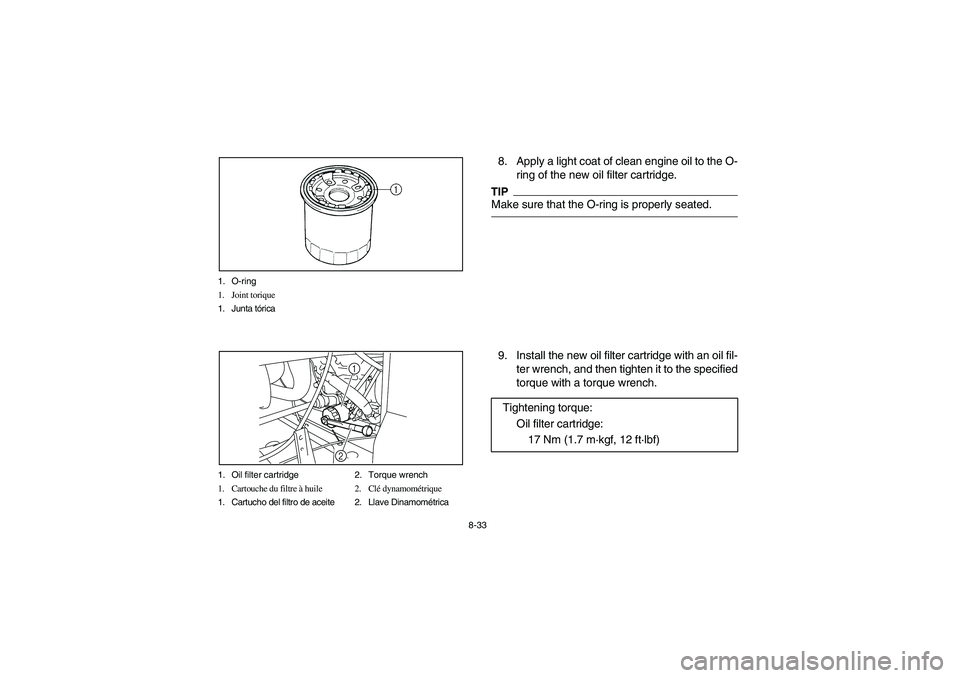
8-33 1. O-ring
1. Joint torique
1. Junta tórica
1. Oil filter cartridge 2. Torque wrench
1. Cartouche du filtre à huile 2. Clé dynamométrique
1. Cartucho del filtro de aceite 2. Llave Dinamométrica
1
2
8. Apply a light coat of clean engine oil to the O-
ring of the new oil filter cartridge.TIPMake sure that the O-ring is properly seated.9. Install the new oil filter cartridge with an oil fil-
ter wrench, and then tighten it to the specified
torque with a torque wrench.
Tightening torque:
Oil filter cartridge:
17 Nm (1.7 m·kgf, 12 ft·lbf)
1RB60-EE.book Page 33 Thursday, April 7, 2011 10:43 AM
Page 354 of 492
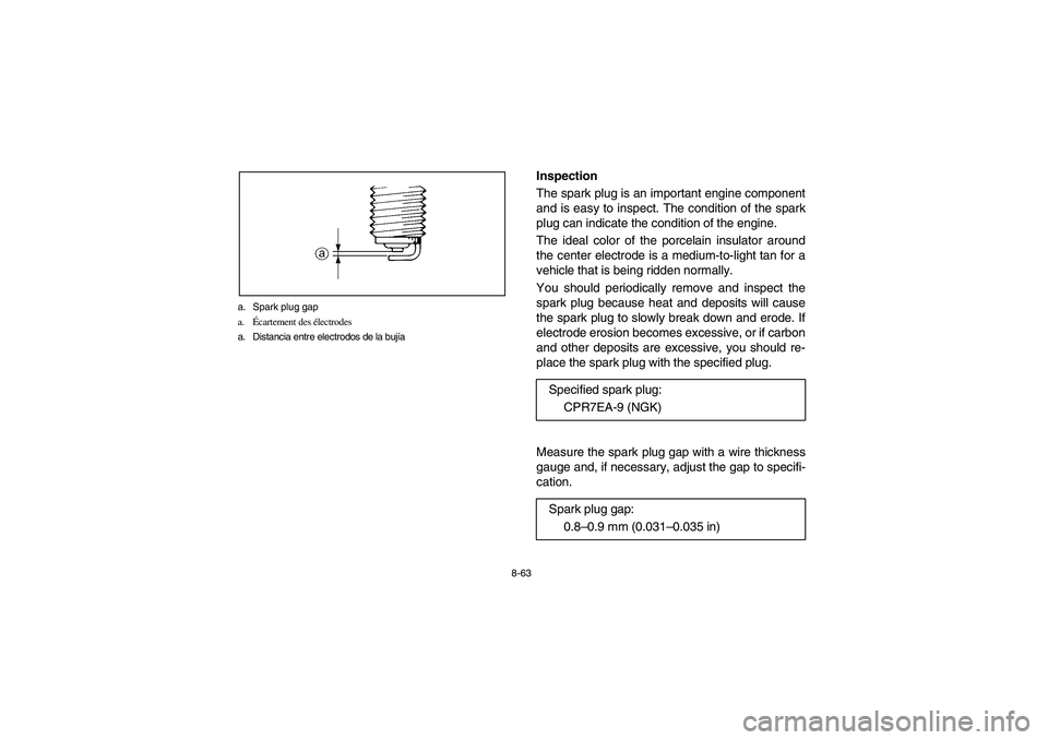
8-63 a. Spark plug gap
a.Écartement des électrodes
a. Distancia entre electrodos de la bujía
Inspection
The spark plug is an important engine component
and is easy to inspect. The condition of the spark
plug can indicate the condition of the engine.
The ideal color of the porcelain insulator around
the center electrode is a medium-to-light tan for a
vehicle that is being ridden normally.
You should periodically remove and inspect the
spark plug because heat and deposits will cause
the spark plug to slowly break down and erode. If
electrode erosion becomes excessive, or if carbon
and other deposits are excessive, you should re-
place the spark plug with the specified plug.
Measure the spark plug gap with a wire thickness
gauge and, if necessary, adjust the gap to specifi-
cation.Specified spark plug:
CPR7EA-9 (NGK)
Spark plug gap:
0.8–0.9 mm (0.031–0.035 in)
1RB60-EE.book Page 63 Thursday, April 7, 2011 10:43 AM
Page 374 of 492
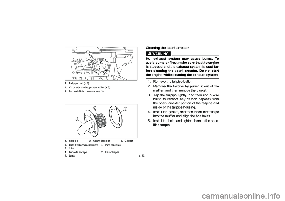
8-83 1. Tailpipe bolt (× 3)
1. Vis de tube d’échappement arrière (× 3)
1. Perno del tubo de escape (× 3)
1
1. Tailpipe 2. Spark arrester 3. Gasket
1. Tube d’échappement arrière 2. Pare-étincelles
3. Joint
1. Tubo de escape 2. Parachispas
3. Junta
3
12
5B410018
Cleaning the spark arrester
WARNING
Hot exhaust system may cause burns. To
avoid burns or fires, make sure that the engine
is stopped and the exhaust system is cool be-
fore cleaning the spark arrester. Do not start
the engine while cleaning the exhaust system.1. Remove the tailpipe bolts.
2. Remove the tailpipe by pulling it out of the
muffler, and then remove the gasket.
3. Tap the tailpipe lightly, and then use a wire
brush to remove any carbon deposits from
the spark arrester portion of the tailpipe and
inside of the tailpipe housing.
4. Install the gasket, and then insert the tailpipe
into the muffler and align the bolt holes.
5. Install the bolts and tighten them to the spec-
ified torque.
1RB60-EE.book Page 83 Thursday, April 7, 2011 10:43 AM
Page 396 of 492
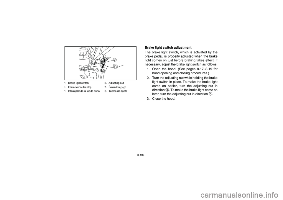
8-105 1. Brake light switch 2. Adjusting nut
1. Contacteur de feu stop 2.Écrou de réglage
1. Interruptor de la luz de freno 2. Tuerca de ajuste
1a
b
2
EVU00880
Brake light switch adjustment
The brake light switch, which is activated by the
brake pedal, is properly adjusted when the brake
light comes on just before braking takes effect. If
necessary, adjust the brake light switch as follows.
1. Open the hood. (See pages 8-17–8-19 for
hood opening and closing procedures.)
2. Turn the adjusting nut while holding the brake
light switch in place. To make the brake light
come on earlier, turn the adjusting nut in
directiona. To make the brake light come on
later, turn the adjusting nut in directionb.
3. Close the hood.
1RB60-EE.book Page 105 Thursday, April 7, 2011 10:43 AM
Page 430 of 492
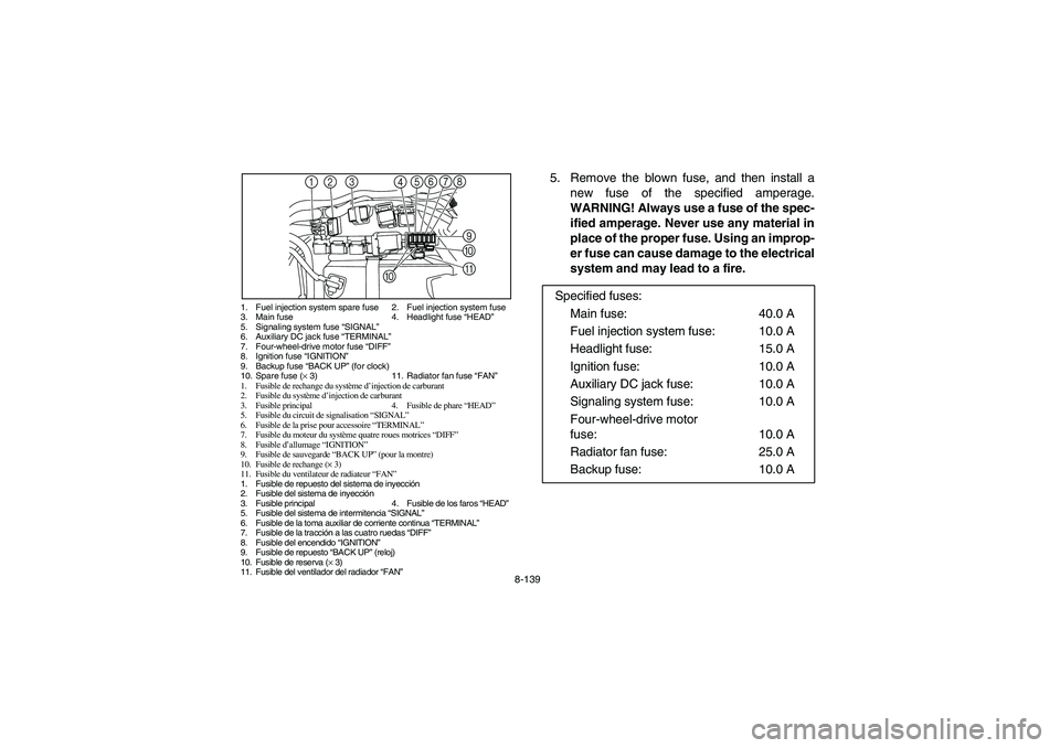
8-139
1. Fuel injection system spare fuse 2. Fuel injection system fuse
3. Main fuse 4. Headlight fuse “HEAD”
5. Signaling system fuse “SIGNAL”
6. Auxiliary DC jack fuse “TERMINAL”
7. Four-wheel-drive motor fuse “DIFF”
8. Ignition fuse “IGNITION”
9. Backup fuse “BACK UP” (for clock)
10. Spare fuse (× 3) 11. Radiator fan fuse “FAN”
1. Fusible de rechange du système d’injection de carburant
2. Fusible du système d’injection de carburant
3. Fusible principal 4. Fusible de phare “HEAD”
5. Fusible du circuit de signalisation “SIGNAL”
6. Fusible de la prise pour accessoire “TERMINAL”
7. Fusible du moteur du système quatre roues motrices “DIFF”
8. Fusible d’allumage “IGNITION”
9. Fusible de sauvegarde “BACK UP” (pour la montre)
10. Fusible de rechange (× 3)
11. Fusible du ventilateur de radiateur “FAN”
1. Fusible de repuesto del sistema de inyección
2. Fusible del sistema de inyección
3. Fusible principal 4. Fusible de los faros “HEAD”
5. Fusible del sistema de intermitencia “SIGNAL”
6. Fusible de la toma auxiliar de corriente continua “TERMINAL”
7. Fusible de la tracción a las cuatro ruedas “DIFF”
8. Fusible del encendido “IGNITION”
9. Fusible de repuesto “BACK UP” (reloj)
10. Fusible de reserva (× 3)
11. Fusible del ventilador del radiador “FAN”
3 2 17
9 5 468
A
@
0
5. Remove the blown fuse, and then install a
new fuse of the specified amperage.
WARNING! Always use a fuse of the spec-
ified amperage. Never use any material in
place of the proper fuse. Using an improp-
er fuse can cause damage to the electrical
system and may lead to a fire.
Specified fuses:
Main fuse: 40.0 A
Fuel injection system fuse: 10.0 A
Headlight fuse: 15.0 A
Ignition fuse: 10.0 A
Auxiliary DC jack fuse: 10.0 A
Signaling system fuse: 10.0 A
Four-wheel-drive motor
fuse: 10.0 A
Radiator fan fuse: 25.0 A
Backup fuse: 10.0 A
1RB60-EE.book Page 139 Thursday, April 7, 2011 10:43 AM
Page 434 of 492
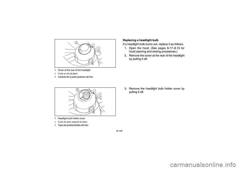
8-143 1. Cover at the rear of the headlight
1. Cache au dos du phare
1. Cubierta de la parte posterior del faro
1. Headlight bulb holder cover
1. Cache du porte-ampoule de phare
1. Tapa del portabombillas del faro
EVU01670
Replacing a headlight bulb
If a headlight bulb burns out, replace it as follows.
1. Open the hood. (See pages 8-17–8-19 for
hood opening and closing procedures.)
2. Remove the cover at the rear of the headlight
by pulling it off.
3. Remove the headlight bulb holder cover by
pulling it off.
1RB60-EE.book Page 143 Thursday, April 7, 2011 10:43 AM
Page 436 of 492
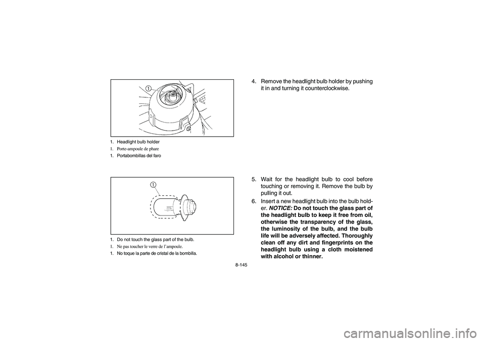
8-145 1. Headlight bulb holder
1. Porte-ampoule de phare
1. Portabombillas del faro
1. Do not touch the glass part of the bulb.
1. Ne pas toucher le verre de l’ampoule.
1. No toque la parte de cristal de la bombilla.
4. Remove the headlight bulb holder by pushing
it in and turning it counterclockwise.
5. Wait for the headlight bulb to cool before
touching or removing it. Remove the bulb by
pulling it out.
6. Insert a new headlight bulb into the bulb hold-
er. NOTICE: Do not touch the glass part of
the headlight bulb to keep it free from oil,
otherwise the transparency of the glass,
the luminosity of the bulb, and the bulb
life will be adversely affected. Thoroughly
clean off any dirt and fingerprints on the
headlight bulb using a cloth moistened
with alcohol or thinner.
1RB60-EE.book Page 145 Thursday, April 7, 2011 10:43 AM
Page 438 of 492
8-147
7. Reinstall the bulb holder by pushing it in and
turning it clockwise.
8. Reinstall the bulb holder cover and the cover
at the rear of the headlight. NOTICE: Make
sure the headlight bulb holder cover is se-
curely fitted over the bulb holder and
seated properly.
9. Close the hood.
10. Adjust the headlight beam if necessary.
1RB60-EE.book Page 147 Thursday, April 7, 2011 10:43 AM
Page 440 of 492
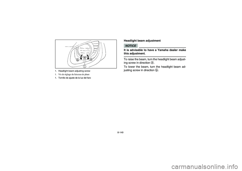
8-149 1. Headlight beam adjusting screw
1. Vis de réglage du faisceau de phare
1. Tornillo de ajuste de la luz del faro
EVU00990
Headlight beam adjustmentNOTICEIt is advisable to have a Yamaha dealer make
this adjustment.To raise the beam, turn the headlight beam adjust-
ing screw in directiona.
To lower the beam, turn the headlight beam ad-
justing screw in directionb.
1RB60-EE.book Page 149 Thursday, April 7, 2011 10:43 AM
Page 442 of 492
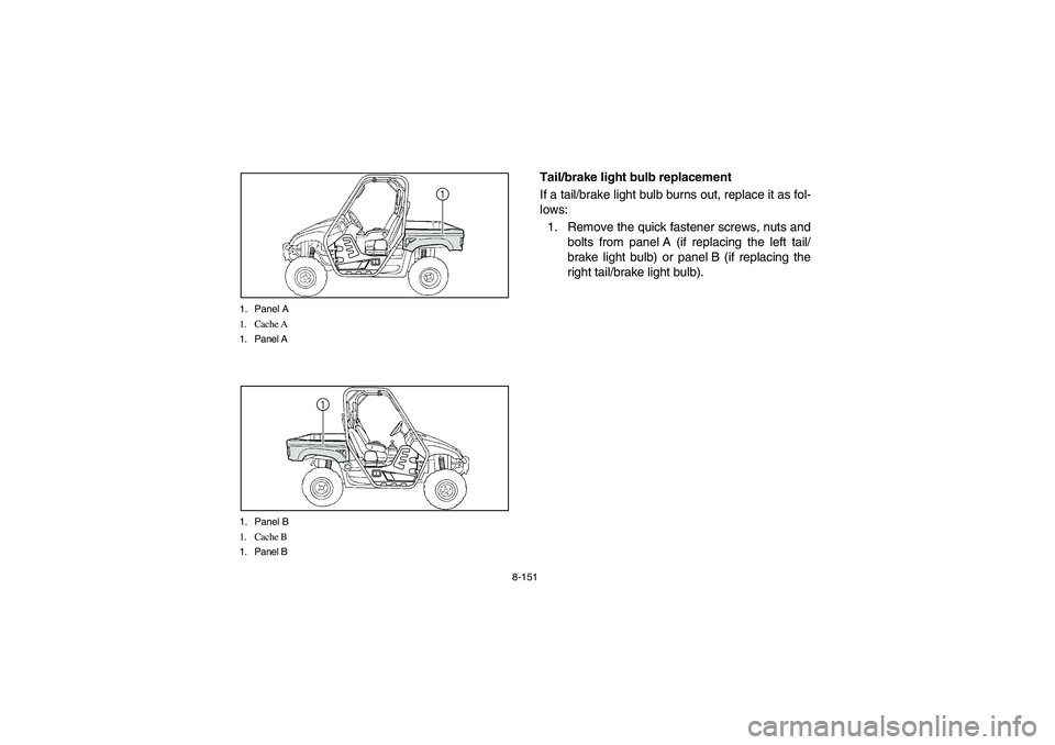
8-151 1. Panel A
1. Cache A
1. Panel A
1
1. Panel B
1. Cache B
1. Panel B
1
EVU01000
Tail/brake light bulb replacement
If a tail/brake light bulb burns out, replace it as fol-
lows:
1. Remove the quick fastener screws, nuts and
bolts from panel A (if replacing the left tail/
brake light bulb) or panel B (if replacing the
right tail/brake light bulb).
1RB60-EE.book Page 151 Thursday, April 7, 2011 10:43 AM