engine YAMAHA SUPERJET 2009 Owner's Guide
[x] Cancel search | Manufacturer: YAMAHA, Model Year: 2009, Model line: SUPERJET, Model: YAMAHA SUPERJET 2009Pages: 76, PDF Size: 4.38 MB
Page 49 of 76
Operation
42
steer away from a boat or other obstacle
that comes into your path.
EJU33301Beaching the watercraft
(1) Make sure that there are no boats, swim-
mers, or obstacles near the beach. Re-
lease the throttle lever about 90 m (300 ft)
before you reach the intended beaching
area.
(2) Approach the beach slowly and stop the
engine before reaching land.
Remember, you need throttle to steer.
(3) Get off the watercraft and pull it up on the
beach. NOTICE: Small pebbles, sand,
seaweed, and other debris can be
sucked into the jet intake and impair
or damage the impeller. Always stop
the engine and get off the watercraft
before beaching it.
[ECJ00491]
EJU37190
Operating in weeded areas
Always avoid operating your watercraft in ar-
eas where weed growth is thick. If traveling in
weeded areas is unavoidable, operate the en-
gine alternately at partial throttle and full throt-
tle. Weeds tend to accumulate more at a
steady speed and at trolling speed. If weeds
clog the intake area and cause cavitation,
clean the jet intake and impeller. (See page
63 for cleaning procedures.)
EJU33362
Post-operation care
To keep your watercraft in top shape, always
take it out of the water after using it and per-
form the following procedures. Leaving the
watercraft in the water for extended periods
will accelerate the rate of normal deterioration
of the jet unit components and hull finish. Ma-
rine organisms and corrosion are some of the
conditions that can adversely affect the life of
many watercraft components.
(1) Remove the watercraft from the water.
(2) Wash down the hull, steering pole, han-
dlebars, and jet unit with fresh water.
(3) Remove the hood and check the engine
compartment for water. To drain excess
water, turn the watercraft onto its port
(left) side. If necessary, turn the water-
craft upside down to drain the water com-
pletely. Place a suitable clean cloth or
carpeting underneath the watercraft to
protect it from abrasions and scratches.
NOTICE: Always turn the watercraft
over onto its port (left) side, otherwise
the water could flow back through the
muffler into the engine. When turning
the watercraft onto its side or invert-
ing it, support the bow and secure the
steering pole, otherwise the steering
pole and handlebars could be bent or
damaged.
[ECJ00581]
TIP:
This watercraft is equipped with an automatic
bilge draining system that removes water
from the engine compartment while you are
underway. However, some residual water will
remain, therefore, wipe it up with a clean
cloth.
(4) Place the watercraft in a horizontal posi-
tion.
UF2F71E0.book Page 42 Thursday, April 10, 2008 11:47 AM
Page 50 of 76
Operation
43
(5) Flush the cooling system to prevent it
from clogging with salt, sand, or dirt. (See
page 45 for flushing procedures.)
(6) If the watercraft will be stored for a week
or more, lubricate internal engine compo-
nents to help prevent corrosion. (See
page 46 for lubrication procedures.)
(7) Rinse the engine and engine compart-
ment with a small amount of water.
NOTICE: Do not use high-pressure
water when rinsing the engine or en-
gine compartment as severe engine
damage could result.
[ECJ00571]
(8) Wipe the engine and engine compart-
ment dry with a clean cloth (repeat step 3,
if necessary).
(9) Wipe the hull, steering pole, handlebars,
and jet unit dry with a clean cloth.
(10) Spray a rust inhibitor on metallic parts to
minimize corrosion.
(11) Allow the engine compartment to air dry
completely before installing the hood.
EJU33421
Transporting
WARNING
EWJ00750
Always turn the fuel cock knob to “OFF”
when transporting the watercraft, other-
wise fuel could leak out into the engine or
engine compartment, which would create
a fire hazard.
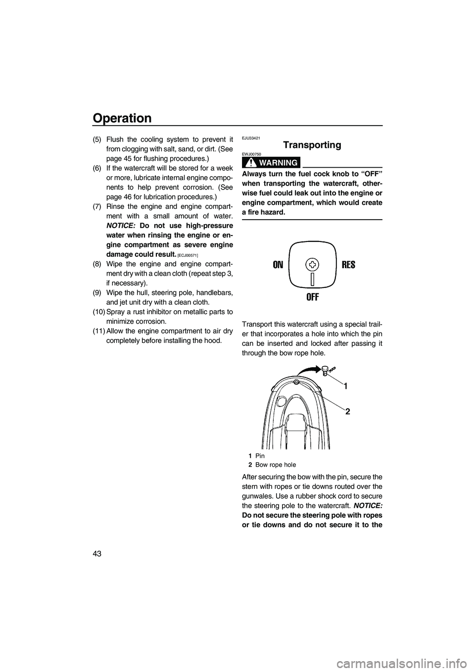
Transport this watercraft using a special trail-
er that incorporates a hole into which the pin
can be inserted and locked after passing it
through the bow rope hole.
After securing the bow with the pin, secure the
stern with ropes or tie downs routed over the
gunwales. Use a rubber shock cord to secure
the steering pole to the watercraft. NOTICE:
Do not secure the steering pole with ropes
or tie downs and do not secure it to the
1Pin
2Bow rope hole
UF2F71E0.book Page 43 Thursday, April 10, 2008 11:47 AM
Page 52 of 76
Maintenance and care
45
EJU33480
Storage
WARNING
EWJ00320
Always turn the fuel cock knob to “OFF”
when storing the watercraft, otherwise
fuel could leak out into the engine or en-
gine compartment, which would create a
fire hazard.
Storage for long periods of time, such as win-
ter storage, requires preventive maintenance
to ensure against deterioration. It is advisable
to have the watercraft serviced by a Yamaha
dealer prior to storage. However, the following
procedures can be performed by the owner.
EJU33513Flushing the cooling system
Flushing the cooling system is essential to
prevent it from clogging with salt, sand, or dirt.
(1) Place the watercraft in a horizontal posi-
tion.
(2) Remove the hood. (See page 17 for hood
removal and installation procedures.)
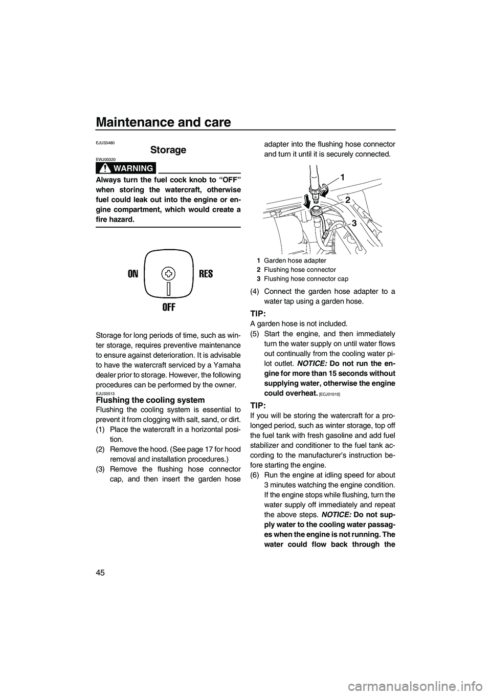
(3) Remove the flushing hose connector
cap, and then insert the garden hoseadapter into the flushing hose connector
and turn it until it is securely connected.
(4) Connect the garden hose adapter to a
water tap using a garden hose.
TIP:
A garden hose is not included.
(5) Start the engine, and then immediately
turn the water supply on until water flows
out continually from the cooling water pi-
lot outlet. NOTICE: Do not run the en-
gine for more than 15 seconds without
supplying water, otherwise the engine
could overheat.
[ECJ01010]
TIP:
If you will be storing the watercraft for a pro-
longed period, such as winter storage, top off
the fuel tank with fresh gasoline and add fuel
stabilizer and conditioner to the fuel tank ac-
cording to the manufacturer’s instruction be-
fore starting the engine.
(6) Run the engine at idling speed for about
3 minutes watching the engine condition.
If the engine stops while flushing, turn the
water supply off immediately and repeat
the above steps. NOTICE: Do not sup-
ply water to the cooling water passag-
es when the engine is not running. The
water could flow back through the
1Garden hose adapter
2Flushing hose connector
3Flushing hose connector cap
UF2F71E0.book Page 45 Thursday, April 10, 2008 11:47 AM
Page 53 of 76
![YAMAHA SUPERJET 2009 Owners Guide Maintenance and care
46
muffler into the engine, causing se-
vere engine damage.
[ECJ00122]
(7) Turn the water supply off, and then force
the remaining water out of the cooling
water passages by alte YAMAHA SUPERJET 2009 Owners Guide Maintenance and care
46
muffler into the engine, causing se-
vere engine damage.
[ECJ00122]
(7) Turn the water supply off, and then force
the remaining water out of the cooling
water passages by alte](/img/51/51310/w960_51310-52.png)
Maintenance and care
46
muffler into the engine, causing se-
vere engine damage.
[ECJ00122]
(7) Turn the water supply off, and then force
the remaining water out of the cooling
water passages by alternately squeezing
and releasing the throttle lever for 10 to
15 seconds.
(8) Stop the engine.
(9) Remove the garden hose adapter and in-
stall the flushing hose connector cap.
(10) Install the hood.
EJU33562Lubrication
(1) Remove the hood. (See page 17 for hood
removal and installation procedures.)
(2) Remove the silencer cap.
(3) Start the engine with the watercraft in a
well-ventilated area. NOTICE: Do not
run the engine for more than 15 sec-
onds without supplying water, other-
wise the engine could overheat.
[ECJ00562]
(4) With the engine running at a fast idle,
quickly spray as much rust inhibitor as
possible through the hole in the silencer
cover. Keep spraying until the engine
stalls (or a maximum of 15 seconds).
WARNING! Do not pour or spray gas-
oline, or any substance other than a
rust inhibitor through the hole in the
silencer cover. Do not spray flamma-
ble rust inhibitor products on enginesurfaces while the engine is hot. Oth-
erwise, a fire or explosion could oc-
cur.
[EWJ00301]
(5) Install the silencer cap securely.
NOTICE: Be sure to install the silencer
cap securely after fogging the engine,
otherwise water could enter the en-
gine and cause damage.
[ECJ00152]
(6) Lubricate all cables such as the throttle,
choke, and steering cables. Use a suit-
able marine grease applicator to pres-
sure-lubricate the cables and purge out
any moisture between the inner and outer
cables.
(7) Lubricate the areas of the watercraft
specified in “Lubrication points” on page
56.
(8) Install the hood.
EJU33681Battery
If the watercraft will not be used for more than
a month, remove the battery from the water-
craft and store it in a cool, dry place.
(1) Disconnect the negative (–) battery lead
first, then the positive (+) battery lead and
breather hose, and then remove the bat-
tery from the watercraft.
(2) Clean the battery casing using fresh wa-
ter.
(3) If the battery terminals are dirty or corrod-
ed, clean them with a wire brush.
(4) Fully charge the battery.
(5) Apply Yamaha Marine Grease or
Yamaha Grease A to the battery termi-
nals, and then store the battery in a cool,
dry place.
(6) Check the battery at least once every 2
months and fully charge it if necessary.
NOTICE: Always keep the battery
charged. Storing a discharged battery
can cause permanent battery damage.
[ECJ00101]
1Silencer cap
UF2F71E0.book Page 46 Thursday, April 10, 2008 11:47 AM
Page 54 of 76
Maintenance and care
47
To check the condition of the battery, check
the specific gravity of the electrolyte or mea-
sure the voltage at both battery terminals.
Charge the battery if the voltage is less than
12 volts.
It is recommended to have a Yamaha dealer
check the specific gravity and charge the bat-
tery. If you maintain the battery yourself, be
sure to read and follow the instructions provid-
ed with the battery tester and charger you
use.
EJU33701Cleaning the watercraft
Clean the watercraft before storing it for a long
period.
(1) Wash down the hull, handlebars, and jet
unit with fresh water.
(2) Rinse the engine and engine compart-
ment with fresh water. Drain all of the wa-
ter and wipe up any remaining moisture
with clean, dry rags. NOTICE: Do not
use high-pressure water when rinsing
the engine and engine compartment
as severe engine damage could result.
[ECJ00111]
(3) Spray the engine’s exterior with a rust in-
hibitor and lubricant.
(4) Wax the hull with a non-abrasive wax.
(5) Wipe all vinyl and rubber components,
such as the engine compartment seals,
with a vinyl protectant. Do not use vinyl
protectant on the riding tray, because it
will make it slippery.
EJU33762
Maintenance and adjustments
Periodic inspection, adjustment, and lubrica-
tion will keep your watercraft in the safest and
most efficient condition possible. Safety is an
obligation of the watercraft owner. Proper
maintenance must be carried out to keep the
exhaust emission and sound levels within the
regulated limits. The most important points of
watercraft inspection, adjustment, and lubri-
cation are explained on the following pages.
See a Yamaha dealer for genuine Yamaha re-
placement parts and optional accessories de-
signed for your watercraft.
Remember, failures that are the result of the
installation of parts or accessories which are
not qualitatively equivalent to genuine
Yamaha parts are not covered by the limited
warranty.
Maintenance, replacement, or repair of the
emission control devices and system may
be performed by any marine SI engine re-
pair establishment or individual. Warranty
repair, however, must be performed at an
authorized Yamaha marine dealership.
WARNING
EWJ00311
Be sure to turn off the engine when you
perform maintenance unless otherwise
specified. If you are not familiar with ma-
chine servicing, this work should be done
by a Yamaha dealer or other qualified me-
chanic.
EJU33781Owner’s/operator’s manual and tool
kit
It is advisable to always carry the owner’s/op-
erator’s manual and tool kit with you whenev-
er you use the watercraft. For your Specific gravity (for reference):
1.28 at 20 °C (68 °F)
UF2F71E0.book Page 47 Thursday, April 10, 2008 11:47 AM
Page 56 of 76
Maintenance and care
49
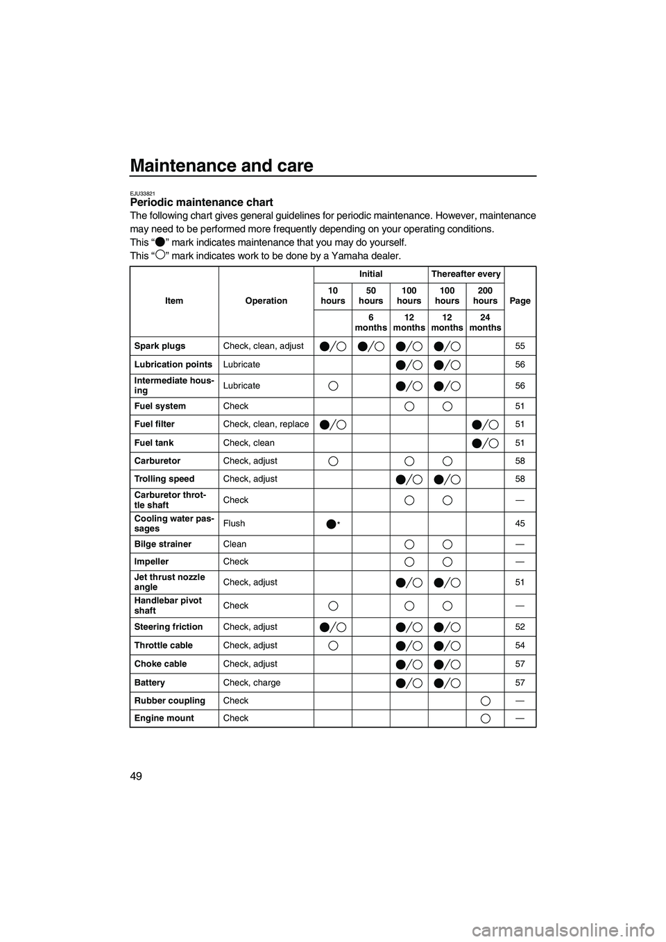
EJU33821Periodic maintenance chart
The following chart gives general guidelines for periodic maintenance. However, maintenance
may need to be performed more frequently depending on your operating conditions.
This “ ” mark indicates maintenance that you may do yourself.
This “ ” mark indicates work to be done by a Yamaha dealer.
Item OperationInitial Thereafter every
Page 10
hours50
hours100
hours100
hours200
hours
6
months12
months12
months24
months
Spark plugsCheck, clean, adjust 55
Lubrication pointsLubricate 56
Intermediate hous-
ingLubricate 56
Fuel systemCheck 51
Fuel filterCheck, clean, replace 51
Fuel tankCheck, clean 51
CarburetorCheck, adjust 58
Trolling speedCheck, adjust 58
Carburetor throt-
tle shaftCheck —
Cooling water pas-
sagesFlush
*45
Bilge strainerClean —
ImpellerCheck —
Jet thrust nozzle
angleCheck, adjust 51
Handlebar pivot
shaftCheck —
Steering frictionCheck, adjust 52
Throttle cableCheck, adjust 54
Choke cableCheck, adjust 57
BatteryCheck, charge 57
Rubber couplingCheck —
Engine mountCheck —
UF2F71E0.book Page 49 Thursday, April 10, 2008 11:47 AM
Page 62 of 76
Maintenance and care
55
(4) Hold the adjuster with one wrench while
tightening the locknut with another
wrench.
(5) Install the handlebar cover and the four
screws.
EJU34374Cleaning and adjusting the spark
plugs
WARNING
EWJ00350
Be careful not to damage the insulator
when removing or installing a spark plug.
A damaged insulator could allow sparks to
escape, which could result in a fire or ex-
plosion.
The spark plug is an important engine compo-
nent and is easy to inspect. The condition of
the spark plug can indicate something about
the condition of the engine. For example, if the
center electrode porcelain is very white, this
could indicate an intake air leak or carburetion
problem in that cylinder. Do not attempt to di-
agnose any problems yourself. Have a
Yamaha dealer service the watercraft.
Remove and inspect the spark plugs periodi-
cally; heat and deposits will cause the spark
plugs to slowly break down and erode. If elec-
trode erosion becomes excessive, or if carbon
and other deposits are excessive, replace the
spark plug with the specified plug.
To remove a spark plug:
(1) Remove the hood. (See page 17 for hood
removal and installation procedures.)
(2) Remove the spark plug cap.(3) Remove the spark plug.
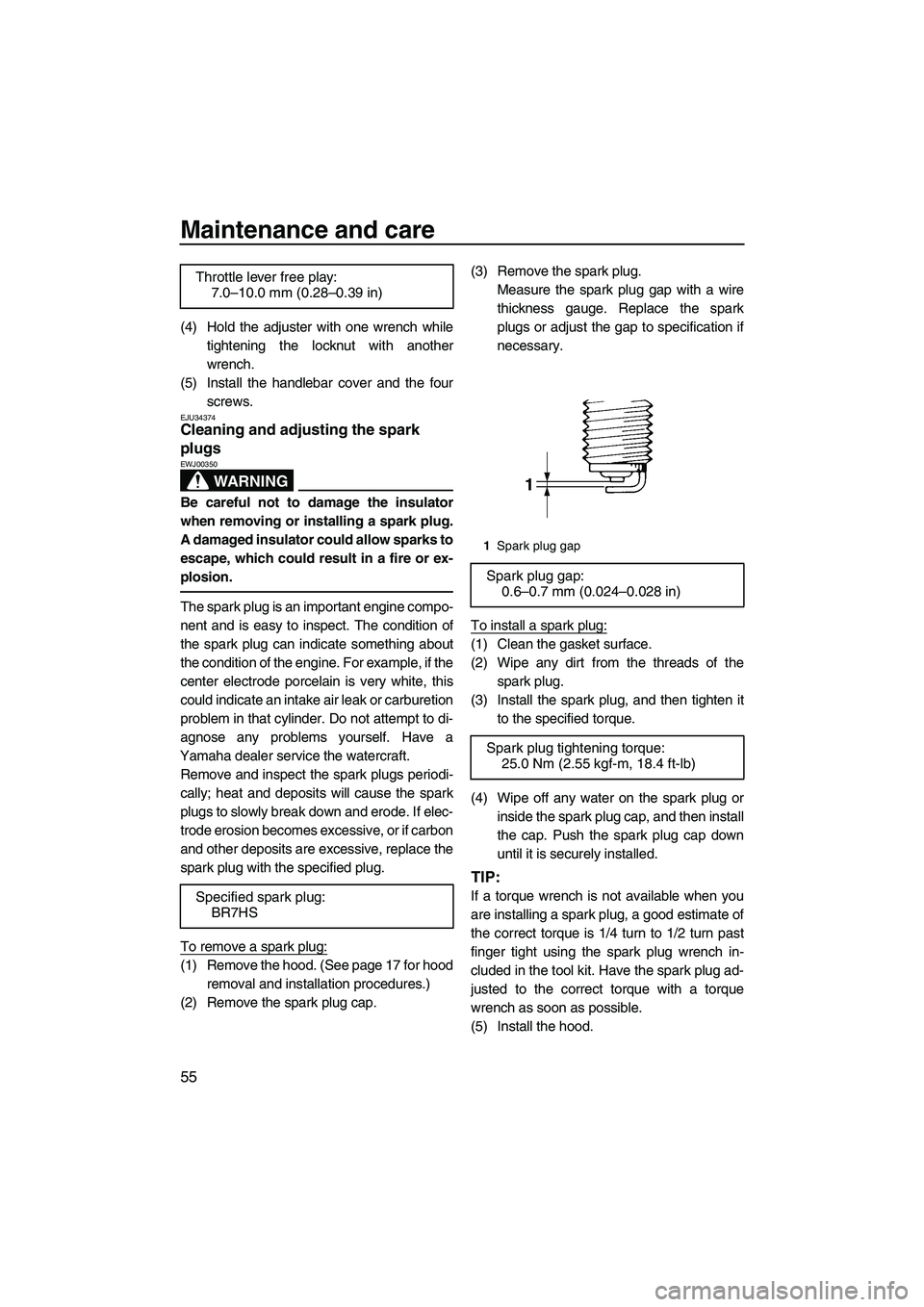
Measure the spark plug gap with a wire
thickness gauge. Replace the spark
plugs or adjust the gap to specification if
necessary.
To install a spark plug:
(1) Clean the gasket surface.
(2) Wipe any dirt from the threads of the
spark plug.
(3) Install the spark plug, and then tighten it
to the specified torque.
(4) Wipe off any water on the spark plug or
inside the spark plug cap, and then install
the cap. Push the spark plug cap down
until it is securely installed.
TIP:
If a torque wrench is not available when you
are installing a spark plug, a good estimate of
the correct torque is 1/4 turn to 1/2 turn past
finger tight using the spark plug wrench in-
cluded in the tool kit. Have the spark plug ad-
justed to the correct torque with a torque
wrench as soon as possible.
(5) Install the hood. Throttle lever free play:
7.0–10.0 mm (0.28–0.39 in)
Specified spark plug:
BR7HS
1Spark plug gap
Spark plug gap:
0.6–0.7 mm (0.024–0.028 in)
Spark plug tightening torque:
25.0 Nm (2.55 kgf-m, 18.4 ft-lb)
UF2F71E0.book Page 55 Thursday, April 10, 2008 11:47 AM
Page 65 of 76
Maintenance and care
58
To remove the battery:
Disconnect the negative (–) battery lead first,
then the positive (+) battery lead and breather
hose, and then remove the battery from the
watercraft.
To replenish the battery:
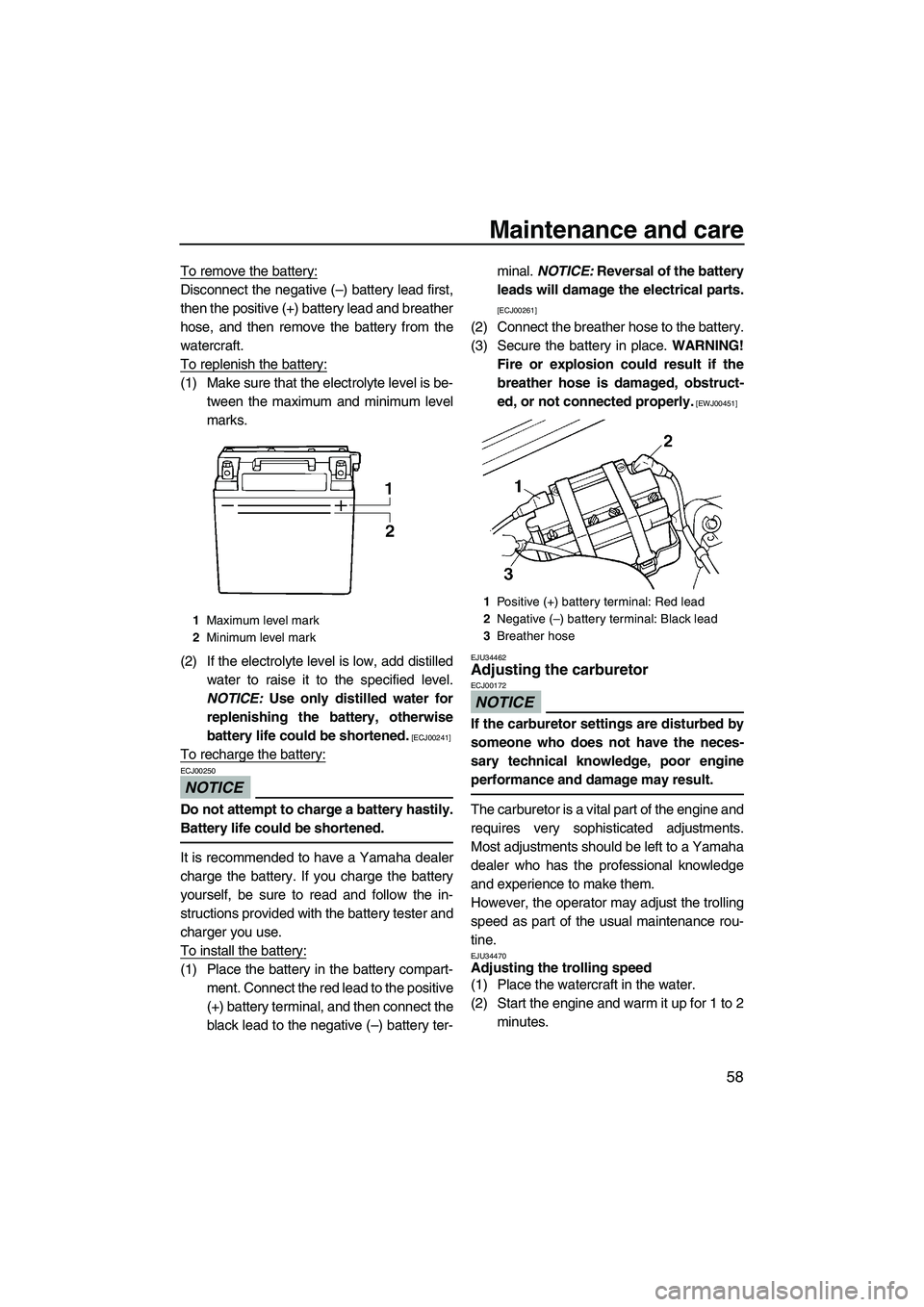
(1) Make sure that the electrolyte level is be-
tween the maximum and minimum level
marks.
(2) If the electrolyte level is low, add distilled
water to raise it to the specified level.
NOTICE: Use only distilled water for
replenishing the battery, otherwise
battery life could be shortened.
[ECJ00241]
To recharge the battery:
NOTICE
ECJ00250
Do not attempt to charge a battery hastily.
Battery life could be shortened.
It is recommended to have a Yamaha dealer
charge the battery. If you charge the battery
yourself, be sure to read and follow the in-
structions provided with the battery tester and
charger you use.
To install the battery:
(1) Place the battery in the battery compart-
ment. Connect the red lead to the positive
(+) battery terminal, and then connect the
black lead to the negative (–) battery ter-minal. NOTICE: Reversal of the battery
leads will damage the electrical parts.
[ECJ00261]
(2) Connect the breather hose to the battery.
(3) Secure the battery in place. WARNING!
Fire or explosion could result if the
breather hose is damaged, obstruct-
ed, or not connected properly.
[EWJ00451]
EJU34462
Adjusting the carburetor
NOTICE
ECJ00172
If the carburetor settings are disturbed by
someone who does not have the neces-
sary technical knowledge, poor engine
performance and damage may result.
The carburetor is a vital part of the engine and
requires very sophisticated adjustments.
Most adjustments should be left to a Yamaha
dealer who has the professional knowledge
and experience to make them.
However, the operator may adjust the trolling
speed as part of the usual maintenance rou-
tine.
EJU34470Adjusting the trolling speed
(1) Place the watercraft in the water.
(2) Start the engine and warm it up for 1 to 2
minutes.
1Maximum level mark
2Minimum level mark
1Positive (+) battery terminal: Red lead
2Negative (–) battery terminal: Black lead
3Breather hose
UF2F71E0.book Page 58 Thursday, April 10, 2008 11:47 AM
Page 66 of 76
Maintenance and care
59
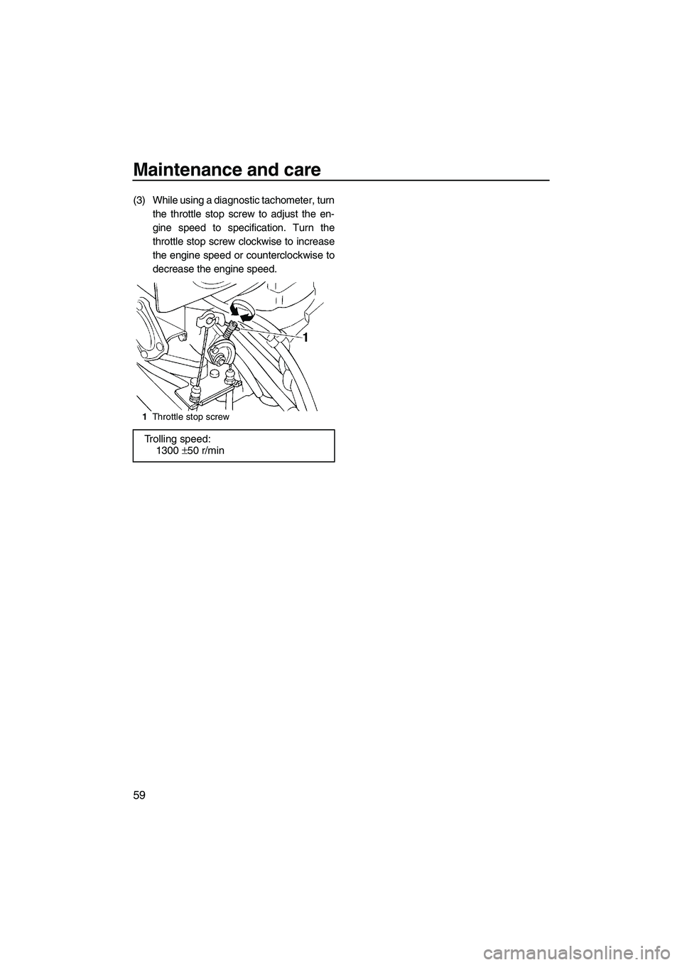
(3) While using a diagnostic tachometer, turn
the throttle stop screw to adjust the en-
gine speed to specification. Turn the
throttle stop screw clockwise to increase
the engine speed or counterclockwise to
decrease the engine speed.
1Throttle stop screw
Trolling speed:
1300 ±50 r/min
UF2F71E0.book Page 59 Thursday, April 10, 2008 11:47 AM
Page 67 of 76
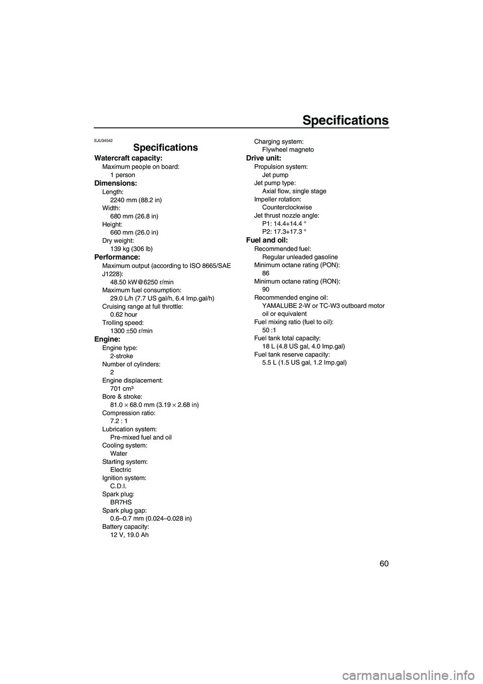
Specifications
60
EJU34542
Specifications
Watercraft capacity:
Maximum people on board:
1 person
Dimensions:
Length:
2240 mm (88.2 in)
Width:
680 mm (26.8 in)
Height:
660 mm (26.0 in)
Dry weight:
139 kg (306 lb)
Performance:
Maximum output (according to ISO 8665/SAE
J1228):
48.50 kW@6250 r/min
Maximum fuel consumption:
29.0 L/h (7.7 US gal/h, 6.4 Imp.gal/h)
Cruising range at full throttle:
0.62 hour
Trolling speed:
1300 ±50 r/min
Engine:
Engine type:
2-stroke
Number of cylinders:
2
Engine displacement:
701 cm³
Bore & stroke:
81.0 × 68.0 mm (3.19 × 2.68 in)
Compression ratio:
7.2 : 1
Lubrication system:
Pre-mixed fuel and oil
Cooling system:
Water
Starting system:
Electric
Ignition system:
C.D.I.
Spark plug:
BR7HS
Spark plug gap:
0.6–0.7 mm (0.024–0.028 in)
Battery capacity:
12 V, 19.0 AhCharging system:
Flywheel magneto
Drive unit:
Propulsion system:
Jet pump
Jet pump type:
Axial flow, single stage
Impeller rotation:
Counterclockwise
Jet thrust nozzle angle:
P1: 14.4+14.4 °
P2: 17.3+17.3 °
Fuel and oil:
Recommended fuel:
Regular unleaded gasoline
Minimum octane rating (PON):
86
Minimum octane rating (RON):
90
Recommended engine oil:
YAMALUBE 2-W or TC-W3 outboard motor
oil or equivalent
Fuel mixing ratio (fuel to oil):
50 :1
Fuel tank total capacity:
18 L (4.8 US gal, 4.0 Imp.gal)
Fuel tank reserve capacity:
5.5 L (1.5 US gal, 1.2 Imp.gal)
UF2F71E0.book Page 60 Thursday, April 10, 2008 11:47 AM