Select switch YAMAHA TENERE 700 RALLY EDITION 2022 Owners Manual
[x] Cancel search | Manufacturer: YAMAHA, Model Year: 2022, Model line: TENERE 700 RALLY EDITION, Model: YAMAHA TENERE 700 RALLY EDITION 2022Pages: 104, PDF Size: 6.33 MB
Page 25 of 104
Instrument and control functions
3-8
3
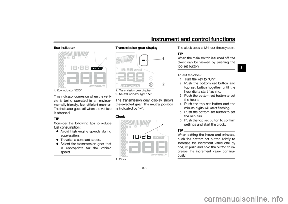
Eco in
dicator
This indicator comes on when the vehi-
cle is being operated in an environ-
mentally friendly, fuel-efficient manner.
The indicator goes off when the vehicle
is stopped.
TIPConsider the following tips to reduce
fuel consumption: Avoid high engine speeds during
acceleration.
Travel at a constant speed.
Select the transmission gear that
is appropriate for the vehicle
speed.
Transmission gear display
The transmission gear display shows
the selected gear. The neutral position
is indicated by “–”.
Clock The clock uses a 12-hour time system.
TIPWhen the main switch is turned off, the
clock can be viewed by pushing the
top set button.To set the clock1. Turn the key to “ON”.
2. Push the bottom set button and
top set button together until the
hour digits start flashing.
3. Push the bottom set button to set the hours.
4. Push the top set button and the minute digits will start flashing.
5. Push the bottom set button to set the minutes.
6. Push the top set button to confirm settings and start the clock.TIPWhen setting the hours and minutes,
push the bottom set button briefly to
increase the increment value one by
one, or push and hold the button to in-
crease the increment value continu-
ously.
1. Eco indicator “ECO”
1
1. Transmission gear display
2. Neutral indicator light “ ”
1. Clock
1
21
UBEHEBE0.book Page 8 Friday, October 22, 2021 10:23 AM
Page 27 of 104
Instrument and control functions
3-10
3
TIP Push the bottom set button to
switch the display in the reverse
order.
The display changes to fuel re-
serve tripmeter “TRIP F” when the
last segment of the fuel meter
starts flashing.
To reset a tripmeter, select it by
pushing the top set button, and
while the digits flash, push the
bottom set button until it is reset.
If you do not reset the fuel reserve
tripmeter manually, it will reset au-
tomatically and disappear from
the display after refueling and
traveling 5 km (3 mi).Fuel reserve tripmeter
When the fuel level becomes low, the
last segment of the fuel meter will start
flashing. The fuel reserve tripmeter
“TRIP F” will automatically appear and
start counting the distance traveled
from that point. In this case, push the
top set button to switch the display in
the following order: TRIP F
→ km/L or L/100 km → AVE_
_._ km/L or AVE_ _._ L/100 km → _ _
°C → Air_ _ °C → ODO → TRIP 1 →
TRIP 2 → TRIP CD → TRIP F
For the UK:
TRIP F → km/L, L/100 km or MPG →
AVE_ _._ km/L, AVE_ _._ L/100 km or
AVE_ _._ MPG → _ _ °C → Air_ _ °C →
ODO → TRIP 1 → TRIP 2 → TRIP CD
→ TRIP F
TIP Push the bottom set button to
change the display in the reverse
order.
You can manually reset the fuel re-
serve tripmeter, or after refueling
and traveling 5 km (3 mi) it will re-
set automatically and disappear
from the display.Countd own tripmeter settin gs
To set the countdown tripmeter, select
it by pushing the top set button. When
the units stop flashing, push the top
and bottom set buttons simultaneously
until the first digit starts flashing. A short press on the top button will incre-
ment the unit from “9” to “0”. Push the
bottom set button to select the next
digit and set it following the same pro-
cedure as the first digit. Push the bot-
tom set button to select the last digit
and follow the same procedure. Push
the bottom set button to confirm the
value.
TIP
The maximum possible entering
value is 900 km or 600 mi.
The countdown tripmeter will start
as soon as you begin riding. When
the countdown reaches “0” the
display changes to the countdown
tripmeter “TRIP CD” and flashes
10 times.
To reset the countdown tripmeter,
select it and while the digits flash,
push the bottom set button until it
is reset.
UBEHEBE0.book Page 10 Friday, October 22, 2021 10:23 AM
Page 28 of 104
Instrument and control functions
3-11
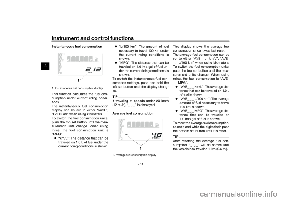
3 Instantaneous fuel consumption
This function calculates the fuel con-
sumption under current riding condi-
tions.
The instantaneous fuel consumption
display can be set to either “km/L”,
“L/100 km” when using kilometers.
To switch the fuel consumption units,
push the top set button until the mea-
surement units change. When using
miles, the fuel consumption unit is
“MPG”.
“km/L”: The distance that can be
traveled on 1.0 L of fuel under the
current riding conditions is shown.
“L/100 km”: The amount of fuel
necessary to travel 100 km under
the current riding conditions is
shown.
“MPG”: The distance that can be
traveled on 1.0 Imp.gal of fuel un-
der the current riding conditions is
shown.
To switch the instantaneous fuel con-
sumption settings, push and hold the
left set button until the display chang-
es.
TIPIf traveling at speeds under 20 km/h
(12 mi/h), “_ _._” is displayed.Averag e fuel consumption This display shows the average fuel
consumption since it was last reset.
The average fuel consumption can be
set to either “AVE_ _._ km/L”, “AVE_
_._ L/100 km” when using kilometers.
To switch the fuel consumption units,
push the top set button until the mea-
surement units change. When using
miles, the fuel consumption is “AVE_
_._ MPG”.
“AVE_ _._ km/L”: The average dis-
tance that can be traveled on 1.0 L
of fuel is shown.
“AVE_ _._ L/100 km”: The average
amount of fuel necessary to travel
100 km is shown.
“AVE_ _._ MPG”: The average dis-
tance that can be traveled on
1.0 Imp.gal of fuel is shown.
To reset the average fuel consumption,
select it and while the digits flash push
the bottom set button until it is reset.
TIPAfter resetting the average fuel con-
sumption, “_ _._” will be shown until
the vehicle has traveled 1 km (0.6 mi).
1. Instantaneous fuel consumption display
1
1. Average fuel consumption display
1
UBEHEBE0.book Page 11 Friday, October 22, 2021 10:23 AM
Page 29 of 104
Instrument and control functions
3-12
3
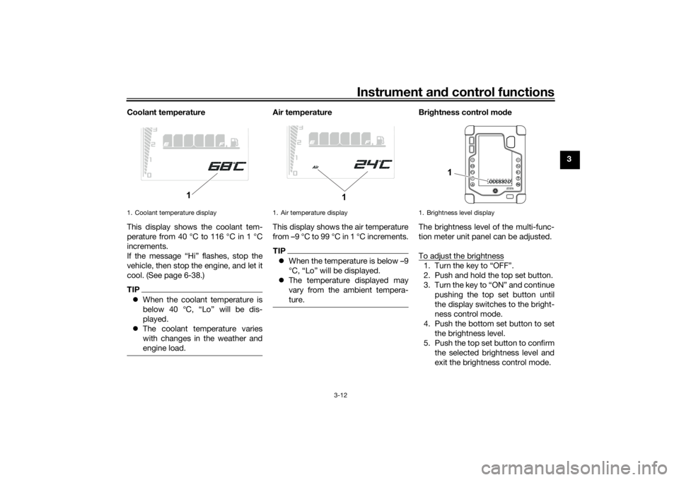
Coolant temperature
This display shows the coolant tem-
perature from 40 °C to 116 °C in 1 °C
increments.
If the message “Hi” flashes, stop the
vehicle, then stop the engine, and let it
cool. (See page 6-38.)
TIP
When the coolant temperature is
below 40 °C, “Lo” will be dis-
played.
The coolant temperature varies
with changes in the weather and
engine load.
Air temperature
This display shows the air temperature
from –9 °C to 99 °C in 1 °C increments.TIPWhen the temperature is below –9
°C, “Lo” will be displayed.
The temperature displayed may
vary from the ambient tempera-
ture.
Brig htness control mo de
The brightness level of the multi-func-
tion meter unit panel can be adjusted.
To adjust the brightness1. Turn the key to “OFF”.
2. Push and hold the top set button.
3. Turn the key to “ON” and continue pushing the top set button until
the display switches to the bright-
ness control mode.
4. Push the bottom set button to set the brightness level.
5. Push the top set button to confirm the selected brightness level and
exit the brightness control mode.
1. Coolant temperature display
1
1. Air temperature display
1
1. Brightness level display
1
UBEHEBE0.book Page 12 Friday, October 22, 2021 10:23 AM
Page 30 of 104
Instrument and control functions
3-13
3
TIPThere are 6 brightness level settings.
EAU1234R
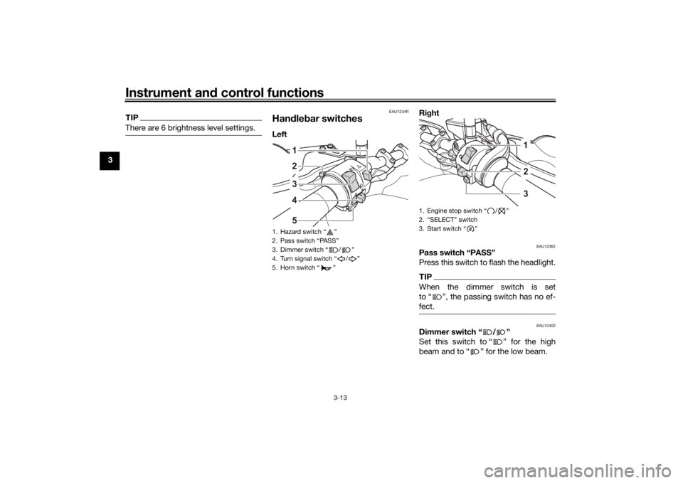
Han dle bar switchesLeft Ri
ght
EAU12362
Pass switch “PASS”
Press this switch to flash the headlight.TIPWhen the dimmer switch is set
to “ ”, the passing switch has no ef-
fect.
EAU12402
Dimmer switch “ / ”
Set this switch to “ ” for the high
beam and to “ ” for the low beam.
1. Hazard switch “ ”
2. Pass switch “PASS”
3. Dimmer switch “ / ”
4. Turn signal switch “ / ”
5. Horn switch “ ”
34512
1. Engine stop switch “ / ”
2. “SELECT” switch
3. Start switch “ ”
231
UBEHEBE0.book Page 13 Friday, October 22, 2021 10:23 AM
Page 31 of 104
Instrument and control functions
3-14
3
EAU12461
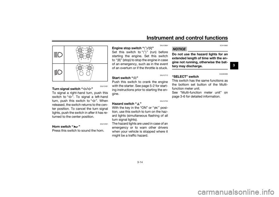
Turn si gnal switch “ / ”
To signal a right-hand turn, push this
switch to “ ”. To signal a left-hand
turn, push this switch to “ ”. When
released, the switch returns to the cen-
ter position. To cancel the turn signal
lights, push the switch in after it has re-
turned to the center position.
EAU12501
Horn switch “ ”
Press this switch to sound the horn.
EAU12664
En gine stop switch “ / ”
Set this switch to “ ” (run) before
starting the engine. Set this switch
to “ ” (stop) to stop the engine in case
of an emergency, such as in the event
of an overturn or if the throttle is stuck.
EAU12713
Start switch “ ”
Push this switch to crank the engine
with the starter. See page 5-2 for start-
ing instructions prior to starting the en-
gine.
EAU12735
Hazar d switch “ ”
With the key in the “ON” or “ ” posi-
tion, use this switch to turn on the haz-
ard lights (simultaneous flashing of all
turn signal lights).
The hazard lights are used in case of an
emergency or to warn other drivers
when your vehicle is stopped where it
might be a traffic hazard.
NOTICE
ECA10062
Do not use the hazar d lig hts for an
exten ded len gth of time with the en-
g ine not runnin g, otherwise the bat-
tery may d ischarge.
EAUM4090
“SELECT” switch
This switch has the same functions as
the bottom set button of the Multi-
function meter unit.
See “Multi-function meter unit” on
page 3-6 for detailed information.
UBEHEBE0.book Page 14 Friday, October 22, 2021 10:23 AM
Page 101 of 104

10-1
10
Index
AABS....................................................... 3-16
ABS off warning light .............................. 3-5
ABS warning light ................................... 3-5
Air filter element and check hose,
replacing and cleaning ....................... 6-15BBattery .................................................. 6-31
Brake and clutch levers, checking
and lubricating ................................... 6-28
Brake and shift pedals, checking and lubricating........................................... 6-27
Brake fluid, changing............................ 6-24
Brake fluid level, checking.................... 6-22
Brake lever............................................ 3-15
Brake lever free play, checking ............ 6-21
Brake light switches ............................. 6-21
Brake pedal .......................................... 3-16CCables, checking and lubricating ......... 6-26
Canister ................................................ 6-10
Care ........................................................ 7-1
Catalytic converter ............................... 3-20
Clutch lever........................................... 3-15
Clutch lever free play, adjusting ........... 6-20
Coolant ................................................. 6-14
Coolant temperature warning light ......... 3-4
Cowlings, removing and installing.......... 6-9DData recording, vehicle........................... 9-2
DC power outlets.................................. 3-26
Diagnostic connector ............................. 9-2
Dimmer switch...................................... 3-13
Drive chain, cleaning and lubricating ... 6-26 Drive chain slack .................................. 6-24
EEngine break-in ...................................... 5-1
Engine oil and oil filter cartridge........... 6-11
Engine overheating .............................. 6-38
Engine serial number ............................. 9-1
Engine stop switch............................... 3-14FFront and rear brake pads, checking ... 6-22
Front fender.......................................... 3-26
Front fork, adjusting ............................. 3-21
Front fork, bleeding .............................. 3-23
Front fork, checking ............................. 6-29
Fuel ...................................................... 3-18
Fuel consumption, tips for reducing ...... 5-4
Fuel tank cap........................................ 3-17
Fuel tank overflow hose ....................... 3-19
Fuses, replacing ................................... 6-32HHandlebar switches ............................. 3-13
Hazard switch ...................................... 3-14
Headlight beams, adjusting ................. 3-21
High beam indicator light ....................... 3-3
Horn switch .......................................... 3-14IIdentification numbers ........................... 9-1
Ignition circuit cut-off system .............. 3-28
Immobilizer system ................................ 3-1
Immobilizer system indicator light ......... 3-5
Indicator lights and warning lights ......... 3-3LLicense plate light ................................ 6-35
Luggage strap holders ......................... 3-26
MMain switch/steering lock ....................... 3-2
Maintenance and lubrication, periodic ... 6-5
Maintenance, emission control
system .................................................. 6-3
Malfunction indicator light (MIL) ............. 3-4
Matte color, caution................................ 7-1
Model label ............................................. 9-1
Multi-function meter unit ........................ 3-6NNeutral indicator light ............................. 3-3OOil pressure warning light ....................... 3-3PParking.................................................... 5-4
Part locations.......................................... 2-1
Pass switch........................................... 3-13RRear suspension, lubricating ................ 6-29SSafety information................................... 1-1
Seat....................................................... 3-20
SELECT switch ..................................... 3-14
Shifting.................................................... 5-3
Shift pedal............................................. 3-15
Shock absorber assembly, adjusting ... 3-23
Sidestand.............................................. 3-28
Sidestand, checking and lubricating .... 6-28
Spark plugs, checking ............................ 6-9
Specifications ......................................... 8-1
Starting the engine ................................. 5-2
Start switch ........................................... 3-14
Steering, checking ................................ 6-30
Storage ................................................... 7-3
UBEHEBE0.book Page 1 Friday, October 22, 2021 10:23 AM