ABS YAMAHA TMAX 2015 Owners Manual
[x] Cancel search | Manufacturer: YAMAHA, Model Year: 2015, Model line: TMAX, Model: YAMAHA TMAX 2015Pages: 112, PDF Size: 6.38 MB
Page 8 of 112
TABLE OF CONTENTSSAFETY INFORMATION................... 1-1
Further safe-riding points................. 1-5
DESCRIPTION ................................... 2-1
Left view .......................................... 2-1
Right view ........................................ 2-2
Controls and instrument s................. 2-3
SMART KEY SYSTEM ....................... 3-1
Smart key system ......... ................... 3-1
Operating range of the smart key
system ....................... ................... 3-2
Handling of the smart key and mechanical key ............................ 3-3
Smart key ........................................ 3-5
Replacing the smart key battery ...... 3-6
Vehicle power on and steering lock release .................................. 3-7
Powering off th e vehicle .................. 3-8
How to lock the steering .................. 3-9
Seat opening and closin g ................ 3-9
Parking mode ................................ 3-10
INSTRUMENT AND CONTROL
FUNCTIONS ....................................... 4-1
Indicator lights and warning lights ... 4-1
Speedometer ................................... 4-2
Tachometer ..................................... 4-3
Multi-function display ....................... 4-3
Handlebar switches ......................... 4-9
Front brake lever ........................... 4-11 Rear brake lever............................ 4-11
Rear brake lock lever .................... 4-12
ABS (for ABS models)...
................ 4-13
Fuel tank cap................................. 4-14
Fuel ............................................... 4-15
Catalytic converter ........................ 4-16
Adjusting the rider backrest........... 4-17
Helmet holder ................................ 4-17
Storage compartments .................. 4-18
Windshield..................................... 4-20
Rear view mirrors .......................... 4-21
Shock absorber assembly ............. 4-22
Sidestand ...................................... 4-22
Ignition circuit cut- off system ......... 4-23
Auxiliary DC connector.................. 4-25
FOR YOUR SAFETY –
PRE-OPERATION CHECKS ............. 5-1
OPERATION AND IMPORTANT
RIDING POINTS ................................. 6-1
Starting the engine .......................... 6-1
Starting off ....................................... 6-2
Acceleration and deceleration ......... 6-3
Braking ............................................ 6-3
Tips for reducing fuel consumption ................................ 6-4
Engine break-in ............................... 6-4
Parking ............................................ 6-5 PERIODIC MAINTENANCE AND
ADJUSTMENT
.................................... 7-1
Owner’s tool kit ................................ 7-2
Periodic maintenance chart for the emission control syst em ............... 7-3
General maintenance and lubrication chart ............................ 7-4
Removing and installing panels ....... 7-8
Checking the spark plugs .............. 7-10
Engine oil and oil filt er cartridge..... 7-11
Coolant .......................................... 7-14
Replacing the air filter element ...... 7-16
Adjusting the engine idling speed............ ............................ .. 7-16
Checking the throttle grip free play ............................................. 7-17
Valve clearance ............................. 7-17
Tires ............................................... 7-18
Cast wheels ................................... 7-20
Checking the front and rear brake
lever free play ............................. 7-20
Adjusting the rear brake lock cable ........................................... 7-21
Checking the rear brake lock ......... 7-22
Checking the front and rear brake pads............................................ 7-22
Checking the brake fluid level ........ 7-23
Changing the brake fluid ................ 7-24
Drive belt slack .............................. 7-24
Checking and lubricating the
cables
......................................... 7-25
2PW-9-E0_1.book 1 ページ 2015年2月19日 木曜日 午後3時30分
Page 28 of 112
4-1
1
2
34
5
6
7
8
9
10
11
12
INSTRUMENT AND CONTROL FUNCTIONS
EAU49397
Indicator ligh ts and warning
lights
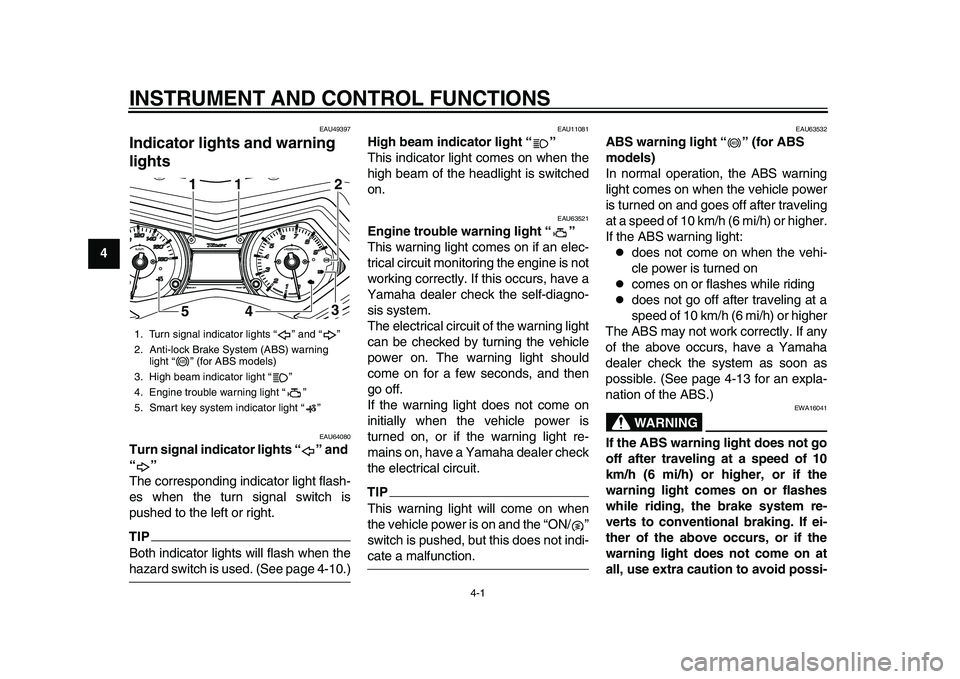
EAU64080
Turn signal indicator lights “ ” and
“”
The corresponding indicator light flash-
es when the turn signal switch is
pushed to the left or right.TIPBoth indicator lights will flash when thehazard switch is used. (See page 4-10.)
EAU11081
High beam indicator light “ ”
This indicator light comes on when the
high beam of the headlight is switched
on.
EAU63521
Engine trouble warning light “ ”
This warning light comes on if an elec-
trical circuit monitoring the engine is not
working correctly. If this occurs, have a
Yamaha dealer check the self-diagno-
sis system.
The electrical circuit of the warning light
can be checked by turning the vehicle
power on. The warning light should
come on for a few seconds, and then
go off.
If the warning light does not come on
initially when the vehicle power is
turned on, or if the warning light re-
mains on, have a Yamaha dealer check
the electrical circuit.TIPThis warning light will come on when
the vehicle power is on and the “ON/ ”
switch is pushed, but this does not indi-cate a malfunction.
EAU63532
ABS warning light “ ” (for ABS
models)
In normal operation, the ABS warning
light comes on when the vehicle power
is turned on and goes off after traveling
at a speed of 10 km/h (6 mi/h) or higher.
If the ABS warning light:
does not come on when the vehi-
cle power is turned on
comes on or flashes while riding
does not go off after traveling at a
speed of 10 km/h (6 mi/h) or higher
The ABS may not work correctly. If any
of the above occurs, have a Yamaha
dealer check the system as soon as
possible. (See page 4-13 for an expla-
nation of the ABS.)WARNING
EWA16041
If the ABS warning light does not go
off after traveling at a speed of 10
km/h (6 mi/h) or higher, or if the
warning light comes on or flashes
while riding, the brake system re-
verts to conventional braking. If ei-
ther of the above occurs, or if the
warning light does not come on at
all, use extra caution to avoid possi-
1. Turn signal indicator lights “ ” and “ ”
2. Anti-lock Brake System (ABS) warning light “ ” (for ABS models)
3. High beam indicator light “ ”
4. Engine trouble warning light “ ”
5. Smart key system indicator light “ ”
1
541
1
3 2
ABS
ABS
2PW-9-E0_1.book 1 ページ 2015年2月19日 木曜日 午後3時30分
Page 29 of 112
INSTRUMENT AND CONTROL FUNCTIONS
4-2
1
2
345
6
7
8
9
10
11
12
ble wheel lock during emergency
braking. Have a Yamaha dealer
check the brake system and electri-
cal circuits as soon as possible.TIP
If the start switch is pushed while
the engine is running, the ABS
warning light will come on, but this
is not a malfunction.
The ABS warning light may come
on when revving the engine with
the scooter on its centerstand, but
this does not indicate a malfunc-tion.
EAU61652
Smart key system indicator light
“”
This indicator light communicates the
status of the smart key system. When
the smart key system is operating nor-
mally, this indicator light will be off. If
there is an error in the smart key sys-
tem, the indicator light will flash. The in-
dicator light will also flash when
communication between the vehicle
and smart key takes place and when
certain smart key system operations are carried out. (See page 3-1.)
TIPWhen the start switch is pushed, the in-
dicator light will come on for about one
second and then go off. If the indicator
light does not come on or go off as nor-
mal, have a Yamaha dealer check thevehicle.
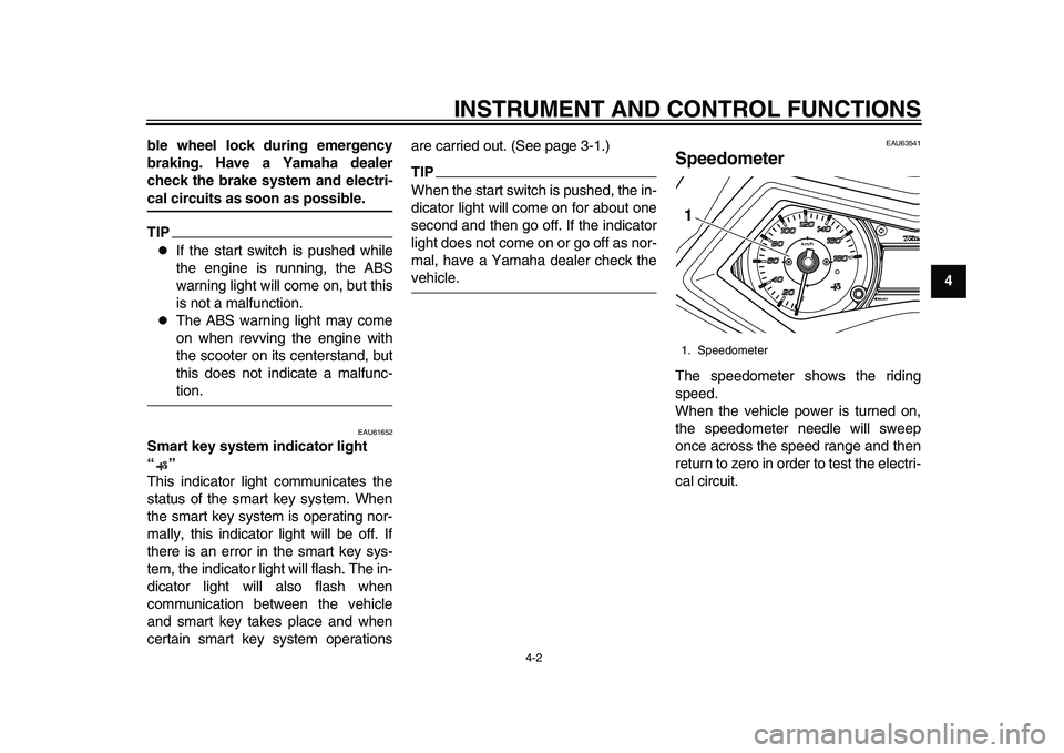
EAU63541
SpeedometerThe speedometer shows the riding
speed.
When the vehicle power is turned on,
the speedometer needle will sweep
once across the speed range and then
return to zero in order to test the electri-
cal circuit.1. Speedometer1
2PW-9-E0_1.book 2 ページ 2015年2月19日 木曜日 午後3時30分
Page 37 of 112
INSTRUMENT AND CONTROL FUNCTIONS
4-10
1
2
345
6
7
8
9
10
11
12
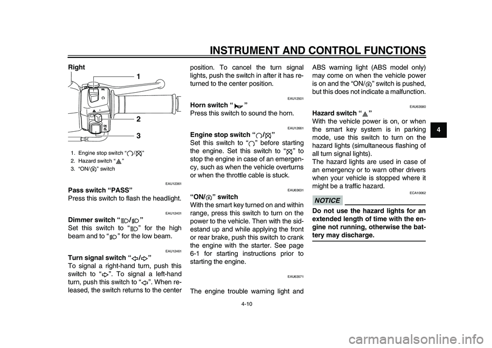
Right
EAU12361
Pass switch “PASS”
Press this switch to flash the headlight.
EAU12401
Dimmer switch “ / ”
Set this switch to “ ” for the high
beam and to “ ” for the low beam.
EAU12461
Turn signal switch “ / ”
To signal a right-hand turn, push this
switch to “ ”. To signal a left-hand
turn, push this switch to “ ”. When re-
leased, the switch returns to the center position. To cancel the turn signal
lights, push the switch in after it has re-
turned to the center position.
EAU12501
Horn switch “ ”
Press this switch to sound the horn.
EAU12661
Engine stop switch “ / ”
Set this switch to “ ” before starting
the engine. Set this switch to “ ” to
stop the engine in case of an emergen-
cy, such as when the vehicle overturns
or when the throttle cable is stuck.
EAU63631
“ON/ ” switch
With the smart key turned on and within
range, press this switch to turn on the
power to the vehicle. Then with the sid-
estand up and while applying the front
or rear brake, push this switch to crank
the engine with the starter. See page
6-1 for starting instructions prior to
starting the engine.
EAU63571
The engine trouble warning light andABS warning light (ABS model only)
may come on when the vehicle power
is on and the “ON/ ” switch is pushed,
but this does not indicate a malfunction.
EAU63580
Hazard switch “ ”
With the vehicle power is on, or when
the smart key system is in parking
mode, use this switch to turn on the
hazard lights (simultaneous flashing of
all turn signal lights).
The hazard lights are used in case of
an emergency or to warn other drivers
when your vehicle is stopped where it
might be a traffic hazard.NOTICE
ECA10062
Do not use the hazard lights for an
extended length of time with the en-
gine not running, otherwise the bat-tery may discharge.
1. Engine stop switch “ / ”
2. Hazard switch “ ”
3. “ON/ ” switch
1
2
3
2PW-9-E0_1.book 10 ページ 2015年2月19日 木曜日 午後3時30分
Page 40 of 112
INSTRUMENT AND CONTROL FUNCTIONS
4-13
1
2
34
5
6
7
8
9
10
11
12
EAU63591
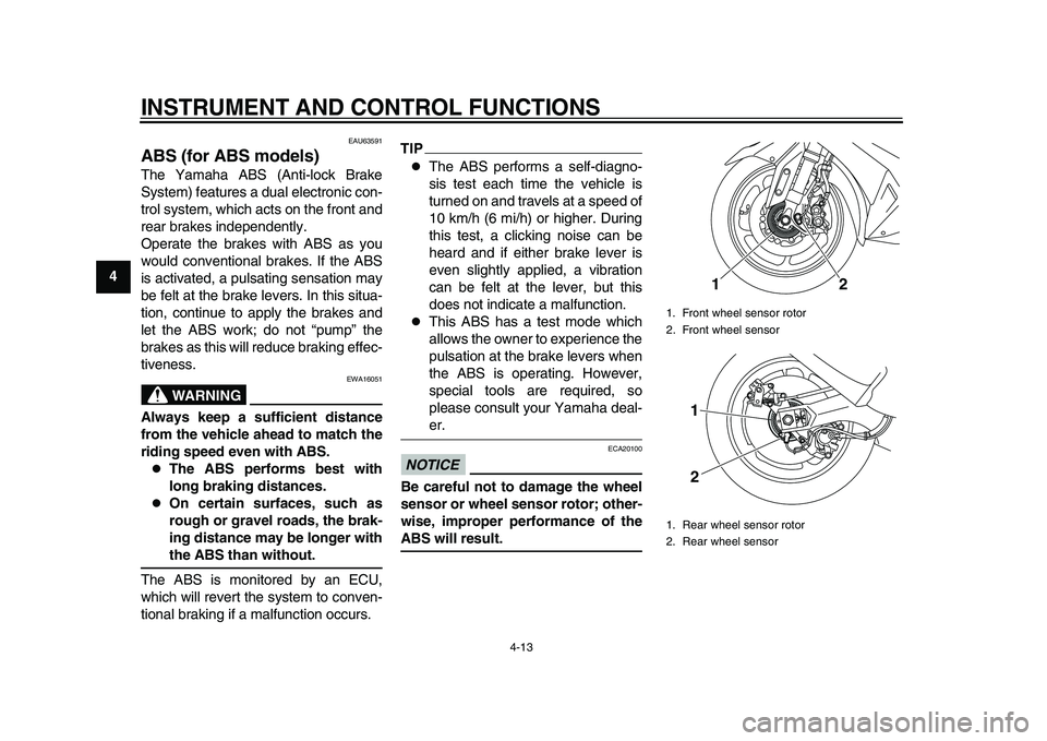
ABS (for ABS models)The Yamaha ABS (Anti-lock Brake
System) features a dual electronic con-
trol system, which acts on the front and
rear brakes independently.
Operate the brakes with ABS as you
would conventional brakes. If the ABS
is activated, a pulsating sensation may
be felt at the brake levers. In this situa-
tion, continue to apply the brakes and
let the ABS work; do not “pump” the
brakes as this will reduce braking effec-
tiveness.
WARNING
EWA16051
Always keep a sufficient distance
from the vehicle ahead to match the
riding speed even with ABS.
The ABS performs best with
long braking distances.
On certain surfaces, such as
rough or gravel roads, the brak-
ing distance may be longer withthe ABS than without.
The ABS is monitored by an ECU,
which will revert the system to conven-
tional braking if a malfunction occurs.
TIP
The ABS performs a self-diagno-
sis test each time the vehicle is
turned on and travels at a speed of
10 km/h (6 mi/h) or higher. During
this test, a clicking noise can be
heard and if either brake lever is
even slightly applied, a vibration
can be felt at the lever, but this
does not indicate a malfunction.
This ABS has a test mode which
allows the owner to experience the
pulsation at the brake levers when
the ABS is operating. However,
special tools are required, so
please consult your Yamaha deal-er.
NOTICE
ECA20100
Be careful not to damage the wheel
sensor or wheel sensor rotor; other-
wise, improper performance of theABS will result.
1. Front wheel sensor rotor
2. Front wheel sensor
1. Rear wheel sensor rotor
2. Rear wheel sensor
12
1
2
2PW-9-E0_1.book 13 ページ 2015年2月19日 木曜日 午後3時30分
Page 49 of 112
INSTRUMENT AND CONTROL FUNCTIONS
4-22
1
2
345
6
7
8
9
10
11
12
EAU46023
Shock absorber assembly
WARNING
EWA10222
This shock absorber assembly con-
tains highly pressurized nitrogen
gas. Read and understand the fol-
lowing information before handling
the shock absorber assembly.
Do not tamper with or attempt to
open the cylinder assembly.
Do not subject the shock ab-
sorber assembly to an open
flame or other high heat source.
This may cause the unit to ex-
plode due to excessive gas
pressure.
Do not deform or damage the
cylinder in any way. Cylinder
damage will result in poor
damping performance.
Do not dispose of a damaged or
worn-out shock absorber as-
sembly yourself. Take the shock
absorber assembly to a Yamahadealer for any service.
EAU15306
SidestandThe sidestand is located on the left side
of the frame. Raise the sidestand or
lower it with your foot while holding the
vehicle upright.TIPThe built-in sidestand switch is part of
the ignition circuit cut-off system, which
cuts the ignition in certain situations.
(See the following section for an expla-
nation of the ignition circuit cut-off sys-tem.)
WARNING
EWA10242
The vehicle must not be ridden with
the sidestand down, or if the sides-
tand cannot be properly moved up
(or does not stay up), otherwise the
sidestand could contact the ground
and distract the operator, resulting
in a possible loss of control.
Yamaha’s ignition circuit cut-off
system has been designed to assist
the operator in fulfilling the respon-
sibility of raising the sidestand be-
fore starting off. Therefore, check
this system regularly and have a Yamaha dealer repair it if it does not
function properly.
2PW-9-E0_1.book 22 ページ 2015年2月19日 木曜日 午後3時30分
Page 56 of 112
OPERATION AND IMPORTANT RIDING POINTS
6-2
1
2
3
4
56
7
8
9
10
11
12 the steering lock (if applied) will be
released. The engine trouble
warning light should come on for a
few seconds and then go off.
For ABS models:
The ABS warning light should
come on when the power of the ve-
hicle is turned on, and go off once
the vehicle reaches a traveling
speed of 10 km/h (6 mi/h) or high-
er.
NOTICE
ECA21980
If the engine warning light or the
ABS warning light (for
ABS-equipped models) does not
come on and then go off as ex-
plained above, see page 4-1 for thewarning light circuit check.
3. Close the throttle completely.
4. Start the engine by pushing the “ON/ ” switch while applying the
front or rear brake.
If the engine does not start within 5
seconds of pressing the “ON/ ”
switch, wait 10 seconds before
pressing the switch again to allow the battery voltage to restore.
NOTICE
ECA11043
For maximum engine life, never ac-
celerate hard when the engine iscold!
EAU45093
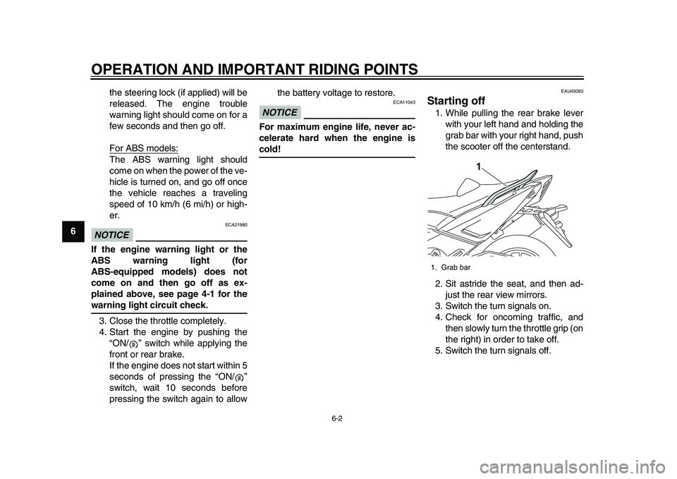
Starting off1. While pulling the rear brake lever
with your left hand and holding the
grab bar with your right hand, push
the scooter off the centerstand.
2. Sit astride the seat, and then ad- just the rear view mirrors.
3. Switch the turn signals on.
4. Check for oncoming traffic, and then slowly turn the throttle grip (on
the right) in order to take off.
5. Switch the turn signals off.1. Grab bar
1
2PW-9-E0_1.book 2 ページ 2015年2月19日 木曜日 午後3時30分
Page 64 of 112
PERIODIC MAINTENANCE AND ADJUSTMENT
7-5
1
2
3
4
5
67
8
9
10
11
12
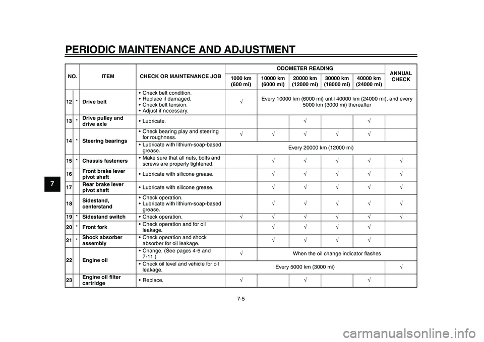
12 *Drive belt Check belt condition.
Replace if damaged.
Check belt tension.
Adjust if necessary.
Every 10000 km (6000 mi) until 40000 km (24000 mi), and every
5000 km (3000 mi) thereafter
13 *Drive pulley and
drive axle Lubricate.
14 *Steering bearings Check bearing play and steering
for roughness.
Lubricate with lithium-soap-based grease. Every 20000 km (12000 mi)
15 *Chassis fasteners Make sure that all nuts, bolts and
screws are properly tightened.
16 Front brake lever
pivot shaft Lubricate with silicone grease.
17 Rear brake lever
pivot shaft Lubricate with silicone grease.
18 Sidestand,
centerstand Check operation.
Lubricate with lithium-soap-based
grease.
19 *Sidestand switch Check operation.
20 *Front fork Check operation and for oil
leakage.
21 *Shock absorber
assembly Check operation and shock
absorber for oil leakage.
22 Engine oil Change. (See pages 4-6 and
7-11.)
When the oil change indicator flashes
Check oil level and vehicle for oil leakage. Every 5000 km (3000 mi)
23 Engine oil filter
cartridge
NO. ITEM CHECK OR MAINTENANCE JOB
ODOMETER READING
ANNUAL
CHECK
1000 km
(600 mi) 10000 km
(6000 mi) 20000 km
(12000 mi) 30000 km
(18000 mi) 40000 km
(24000 mi)2PW-9-E0_1.book 5 ページ 2015年2月19日 木曜日 午後3時30分
Page 68 of 112
PERIODIC MAINTENANCE AND ADJUSTMENT
7-9
1
2
3
4
5
67
8
9
10
11
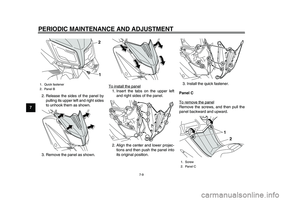
12 2. Release the sides of the panel by
pulling its upper left and right sides
to unhook them as shown.
3. Remove the panel as shown. To install the panel
1. Insert the tabs on the upper left
and right sides of the panel.
2. Align the center and lower projec- tions and then push the panel into
its original position. 3. Install the quick fastener.
Panel C
To remove the panel
Remove the screws, and then pull the
panel backward and upward.
1. Quick fastener
2. Panel B
12
1. Screw
2. Panel C
2
1
2PW-9-E0_1.book 9 ページ 2015年2月19日 木曜日 午後3時30分
Page 90 of 112
PERIODIC MAINTENANCE AND ADJUSTMENT
7-31
1
2
3
4
5
67
8
9
10
11
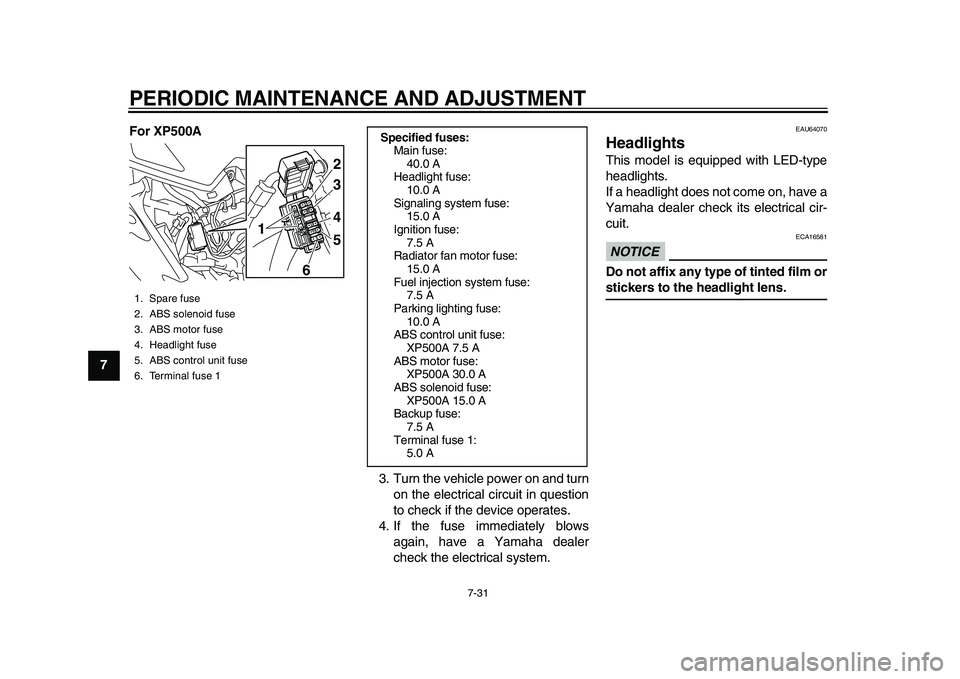
12 For XP500A
3. Turn the vehicle power on and turnon the electrical circuit in question
to check if the device operates.
4. If the fuse immediately blows again, have a Yamaha dealer
check the electrical system.
EAU64070
HeadlightsThis model is equipped with LED-type
headlights.
If a headlight does not come on, have a
Yamaha dealer check its electrical cir-
cuit.NOTICE
ECA16581
Do not affix any type of tinted film orstickers to the headlight lens.
1. Spare fuse
2. ABS solenoid fuse
3. ABS motor fuse
4. Headlight fuse
5. ABS control unit fuse
6. Terminal fuse 1
1
2
4 3
5
6
Specified fuses: Main fuse:40.0 A
Headlight fuse:
10.0 A
Signaling system fuse: 15.0 A
Ignition fuse: 7.5 A
Radiator fan motor fuse:
15.0 A
Fuel injection system fuse: 7.5 A
Parking lighting fuse: 10.0 A
ABS control unit fuse:
XP500A 7.5 A
ABS motor fuse: XP500A 30.0 A
ABS solenoid fuse: XP500A 15.0 A
Backup fuse:
7.5 A
Terminal fuse 1: 5.0 A
2PW-9-E0_1.book 31 ページ 2015年2月19日 木曜日 午後3時30分