AUX YAMAHA TMAX 2015 Owners Manual
[x] Cancel search | Manufacturer: YAMAHA, Model Year: 2015, Model line: TMAX, Model: YAMAHA TMAX 2015Pages: 112, PDF Size: 6.38 MB
Page 8 of 112
TABLE OF CONTENTSSAFETY INFORMATION................... 1-1
Further safe-riding points................. 1-5
DESCRIPTION ................................... 2-1
Left view .......................................... 2-1
Right view ........................................ 2-2
Controls and instrument s................. 2-3
SMART KEY SYSTEM ....................... 3-1
Smart key system ......... ................... 3-1
Operating range of the smart key
system ....................... ................... 3-2
Handling of the smart key and mechanical key ............................ 3-3
Smart key ........................................ 3-5
Replacing the smart key battery ...... 3-6
Vehicle power on and steering lock release .................................. 3-7
Powering off th e vehicle .................. 3-8
How to lock the steering .................. 3-9
Seat opening and closin g ................ 3-9
Parking mode ................................ 3-10
INSTRUMENT AND CONTROL
FUNCTIONS ....................................... 4-1
Indicator lights and warning lights ... 4-1
Speedometer ................................... 4-2
Tachometer ..................................... 4-3
Multi-function display ....................... 4-3
Handlebar switches ......................... 4-9
Front brake lever ........................... 4-11 Rear brake lever............................ 4-11
Rear brake lock lever .................... 4-12
ABS (for ABS models)...
................ 4-13
Fuel tank cap................................. 4-14
Fuel ............................................... 4-15
Catalytic converter ........................ 4-16
Adjusting the rider backrest........... 4-17
Helmet holder ................................ 4-17
Storage compartments .................. 4-18
Windshield..................................... 4-20
Rear view mirrors .......................... 4-21
Shock absorber assembly ............. 4-22
Sidestand ...................................... 4-22
Ignition circuit cut- off system ......... 4-23
Auxiliary DC connector.................. 4-25
FOR YOUR SAFETY –
PRE-OPERATION CHECKS ............. 5-1
OPERATION AND IMPORTANT
RIDING POINTS ................................. 6-1
Starting the engine .......................... 6-1
Starting off ....................................... 6-2
Acceleration and deceleration ......... 6-3
Braking ............................................ 6-3
Tips for reducing fuel consumption ................................ 6-4
Engine break-in ............................... 6-4
Parking ............................................ 6-5 PERIODIC MAINTENANCE AND
ADJUSTMENT
.................................... 7-1
Owner’s tool kit ................................ 7-2
Periodic maintenance chart for the emission control syst em ............... 7-3
General maintenance and lubrication chart ............................ 7-4
Removing and installing panels ....... 7-8
Checking the spark plugs .............. 7-10
Engine oil and oil filt er cartridge..... 7-11
Coolant .......................................... 7-14
Replacing the air filter element ...... 7-16
Adjusting the engine idling speed............ ............................ .. 7-16
Checking the throttle grip free play ............................................. 7-17
Valve clearance ............................. 7-17
Tires ............................................... 7-18
Cast wheels ................................... 7-20
Checking the front and rear brake
lever free play ............................. 7-20
Adjusting the rear brake lock cable ........................................... 7-21
Checking the rear brake lock ......... 7-22
Checking the front and rear brake pads............................................ 7-22
Checking the brake fluid level ........ 7-23
Changing the brake fluid ................ 7-24
Drive belt slack .............................. 7-24
Checking and lubricating the
cables
......................................... 7-25
2PW-9-E0_1.book 1 ページ 2015年2月19日 木曜日 午後3時30分
Page 9 of 112
TABLE OF CONTENTS
Checking and lubricating the throttle grip and cable ................ 7-25
Lubricating the front and rear brake levers ............................... 7-25
Checking and lubricating the
centerstand and sidestand ......... 7-26
Checking the front fork .................. 7-27
Checking the steering.................... 7-27
Checking the wheel bearings ........ 7-28
Battery ........................................... 7-28
Replacing the fuses ....................... 7-29
Headlights ..... ............................. ... 7-31
Auxiliary light .......... ....................... 7-32
Tail/brake light ............................... 7-32
Replacing a front turn signal light bulb ............................................ 7-32
Rear turn signal light bulb.............. 7-33
Replacing the license plate light bulb ............................................ 7-33
Troubleshooting............................. 7-34
Troubleshooting charts .................. 7-36
Emergency mode .......................... 7-38
SCOOTER CARE AND STORAGE ... 8-1
Matte color caution .......................... 8-1
Care................................................. 8-1
Storage ............................................ 8-4 SPECIFICATIONS
............................. 9-1
CONSUMER INFORMATION .......... 10-1
Identification numbers ................... 10-1
INDEX .............................................. 11-1
2PW-9-E0_1.book 2 ページ 2015年2月19日 木曜日 午後3時30分
Page 17 of 112
DESCRIPTION
2-3
123
4
5
6
7
8
9
10
11
12
EAU10431
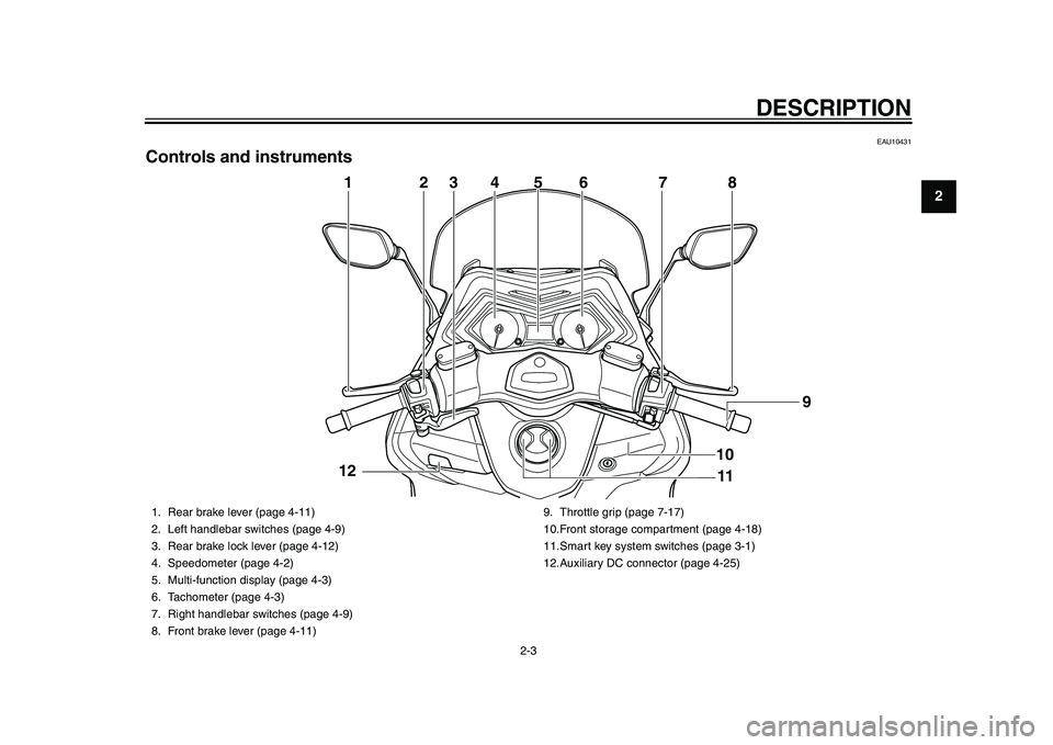
Controls and instruments
4
2
3
6
7
8
1
11 9
5
10
12
1. Rear brake lever (page 4-11)
2. Left handlebar switches (page 4-9)
3. Rear brake lock lever (page 4-12)
4. Speedometer (page 4-2)
5. Multi-function display (page 4-3)
6. Tachometer (page 4-3)
7. Right handlebar switches (page 4-9)
8. Front brake lever (page 4-11) 9. Throttle grip (page 7-17)
10.Front storage compartment (page 4-18)
11.Smart key system switches (page 3-1)
12.Auxiliary DC connector (page 4-25)
2PW-9-E0_1.book 3 ページ 2015年2月19日 木曜日 午後3時30分
Page 52 of 112
INSTRUMENT AND CONTROL FUNCTIONS
4-25
1
2
34
5
6
7
8
9
10
11
12
EAU63800
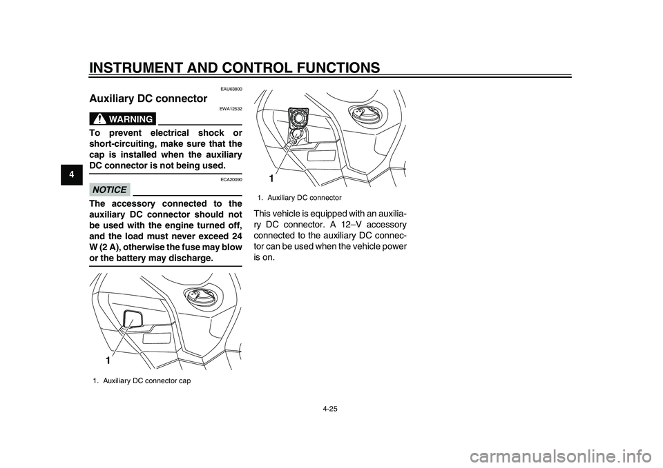
Auxiliary DC connector
WARNING
EWA12532
To prevent electrical shock or
short-circuiting, make sure that the
cap is installed when the auxiliaryDC connector is not being used.NOTICE
ECA20090
The accessory connected to the
auxiliary DC connector should not
be used with the engine turned off,
and the load must never exceed 24
W (2 A), otherwise the fuse may blowor the battery may discharge. This vehicle is equipped with an auxilia-
ry DC connector. A 12–V accessory
connected to the auxiliary DC connec-
tor can be used when the vehicle power
is on.1. Auxiliary DC connector cap
1
1. Auxiliary DC connector
1
2PW-9-E0_1.book 25 ページ 2015年2月19日 木曜日 午後3時30分
Page 87 of 112

PERIODIC MAINTENANCE AND ADJUSTMENT
7-28
1
2
3
4
5
678
9
10
11
12
EAU23292
Checking the wheel bearingsThe front and rear wheel bearings must
be checked at the intervals specified in
the periodic maintenance and lubrica-
tion chart. If there is play in the wheel
hub or if the wheel does not turn
smoothly, have a Yamaha dealer check
the wheel bearings.
EAU63751
BatteryThe battery is located behind the auxil-
iary DC connector. (See page 4-25.)
This model is equipped with a VRLA
(Valve Regulated Lead Acid) battery.
There is no need to check the electro-
lyte or to add distilled water. However,
the battery lead connections need to be
checked and, if necessary, tightened.
WARNING
EWA10761
Electrolyte is poisonous and
dangerous since it contains sul-
furic acid, which causes severe
burns. Avoid any contact with skin, eyes or clothing and al-
ways shield your eyes when
working near batteries. In case
of contact, administer the fol-
lowing FIRST AID.
EXTERNAL: Flush with plenty
of water.
INTERNAL: Drink large quan- tities of water or milk and im-
mediately call a physician.
EYES: Flush with water for 15 minutes and seek prompt
medical attention.
Batteries produce explosive hy-
drogen gas. Therefore, keep
sparks, flames, cigarettes, etc.,
away from the battery and pro-
vide sufficient ventilation when
charging it in an enclosed
space.
KEEP THIS AND ALL BATTER-
IES OUT OF THE REACH OFCHILDREN.
To charge the battery
Have a Yamaha dealer charge the bat-
tery as soon as possi ble if it seems to
have discharged. Keep in mind that the
1. Negative battery lead (black)
2. Positive battery lead (red)
3. Battery
2
3 1
2PW-9-E0_1.book 28 ページ 2015年2月19日 木曜日 午後3時30分
Page 91 of 112
PERIODIC MAINTENANCE AND ADJUSTMENT
7-32
1
2
3
4
5
678
9
10
11
12
EAU54501
Auxiliary lightThis model is equipped with LED-type
auxiliary lights.
If an auxiliary light does not come on,
have a Yamaha dealer check it.
EAU24182
Tail/brake lightThis model is equipped with an
LED-type tail/brake light.
If the tail/brake light does not come on,
have a Yamaha dealer check it.
EAU52321
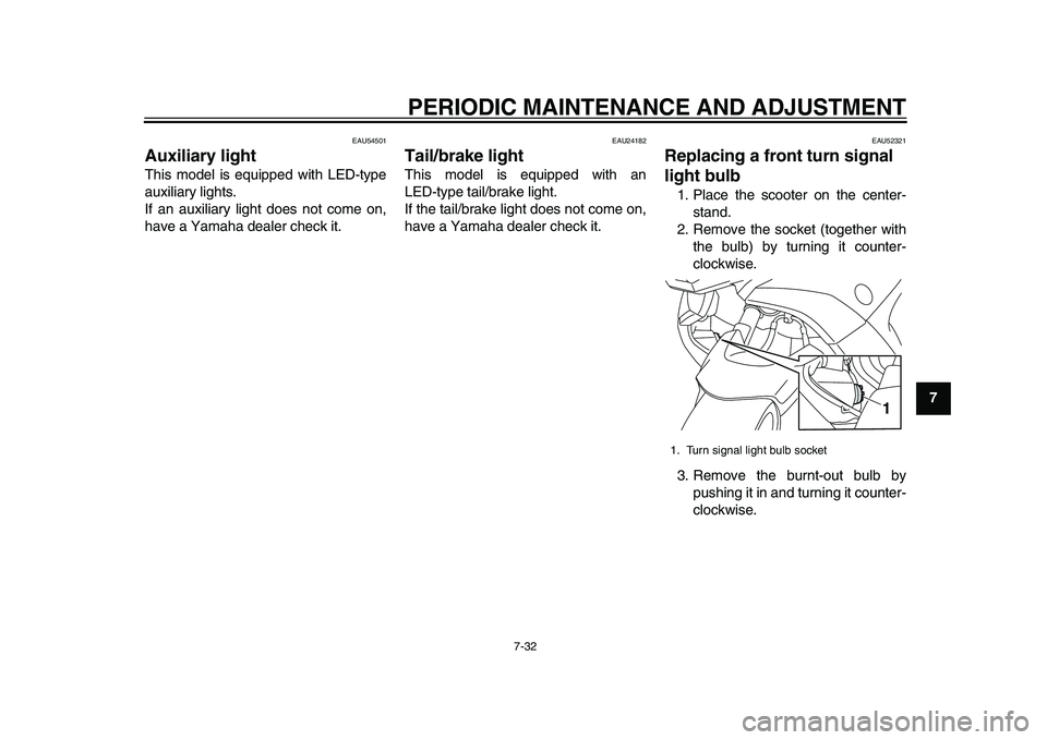
Replacing a front turn signal
light bulb1. Place the scooter on the center- stand.
2. Remove the socket (together with the bulb) by turning it counter-
clockwise.
3. Remove the burnt-out bulb by pushing it in and turning it counter-
clockwise.1. Turn signal light bulb socket
1
2PW-9-E0_1.book 32 ページ 2015年2月19日 木曜日 午後3時30分
Page 104 of 112
SPECIFICATIONS
9-2
1
2
3
4
5
6
7
89
10
11
12
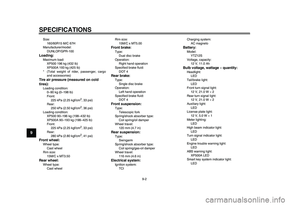
Size: 160/60R15 M/C 67H
Manufacturer/model:
DUNLOP/GPR-100Loading:Maximum load:XP500 196 kg (432 lb)
XP500A 193 kg (425 lb)
* (Total weight of rider, passenger, cargo and accessories)Tire air pressure (measured on cold
tires):Loading condition:0–90 kg (0–198 lb)
Front:225 kPa (2.25 kgf/cm
2, 33 psi)
Rear: 250 kPa (2.50 kgf/cm2, 36 psi)
Loading condition: XP500 90–196 kg (198–432 lb)
XP500A 90–193 kg (198–425 lb)
Front:225 kPa (2.25 kgf/cm2, 33 psi)
Rear:
280 kPa (2.80 kgf/cm2, 41 psi)
Front wheel:Wheel type: Cast wheel
Rim size:
15M/C x MT3.50Rear wheel:Wheel type:Cast wheel Rim size:
15M/C x MT5.00
Front brake:Type:Dual disc brake
Operation: Right hand operation
Specified brake fluid:
DOT 4Rear brake:Type:Single disc brake
Operation:
Left hand operation
Specified brake fluid: DOT 4Front suspension:Type:
Telescopic fork
Spring/shock absorber type: Coil spring/oil damper
Wheel travel: 120 mm (4.7 in)Rear suspension:Type:Swingarm
Spring/shock absorber type: Coil spring/gas-oil damper
Wheel travel:
116 mm (4.6 in)Electrical system:Ignition system:TCI Charging system:
AC magneto
Battery:Model:YTZ12S
Voltage, capacity: 12 V, 11.0 AhBulb voltage, wattage quantity:Headlight:
LED
Tail/brake light: LED
Front turn signal light:
12 V, 21.0 W 2
Rear turn signal light: 12 V, 21.0 W 2
Auxiliary light: LED
License plate light:
12 V, 5.0 W 1
Meter lighting: LED
High beam indicator light: LED
Turn signal indicator light:
LED
Engine trouble warning light: LED
ABS warning light: XP500A LED
Smart key system indicator light:
LED
2PW-9-E0_1.book 2 ページ 2015年2月19日 木曜日 午後3時30分
Page 108 of 112
11-1
1
2
3
4
5
6
7
8
9
1011
12
INDEXAABS (for ABS models) .............................4-13
ABS warning light (for ABS models) ..........4-1
Acceleration and deceleration....................6-3
Air filter element, replacing ......................7-16
Auxiliary DC connector ............................4-25
Auxiliary light ............................................7-32BBattery......................................................7-28
Brake fluid, changing ...............................7-24
Brake fluid level, checking .......................7-23
Brake lever, front......................................4-11
Brake lever, rear ......................................4-11
Brake levers, lubricating...........................7-25
Braking .......................................................6-3CCables, checking and lubricating .............7-25
Care ...........................................................8-1
Catalytic converter ...................................4-16
Centerstand and sidestand, checking and lubricating .......................................7-26
Coolant.....................................................7-14DDimmer switch .........................................4-10
Drive belt slack.........................................7-24EEmergency mode .....................................7-38
Engine break-in ..........................................6-4
Engine idling speed..................................7-16
Engine oil and oil filter cartridge ...............7-11
Engine serial number ...............................10-1
Engine stop switch ...................................4-10
Engine trouble warning light.......................4-1
FFront and rear brak e lever free play,
checking ................................................ 7-20
Front and rear brake pads, checking ....... 7-22
Front fork, checking ................................. 7-27
Fuel.......................................................... 4-15
Fuel consumption, tips for reducing........... 6-4
Fuel tank cap ........................................... 4-14
Fuses, replacing ...................................... 7-29HHandlebar switches ................................... 4-9
Hazard switch .......................................... 4-10
Headlights................................................ 7-31
Helmet holder .......................................... 4-17
High beam indicator light ........................... 4-1
Horn switch .............................................. 4-10
How to lock the steering ............................ 3-9IIdentification numbers ............................. 10-1
Ignition circuit cut-off system ................... 4-23
Indicator lights and warning lights ............. 4-1KKey, handling of smart and mechanical
key........................................................... 3-3LLicense plate light bulb, replacing ........... 7-33MMaintenance and lubrication, periodic ....... 7-4
Maintenance, emission control system...... 7-3
Matte color, caution ................................... 8-1
Model label .............................................. 10-2
Multi-function display ................................. 4-3OON/Start switch........................................ 4-10 Operating range of the smart key
system .................................................... 3-2
PPanels, removing and installing ................ 7-8
Parking ...................................................... 6-5
Parking mode .......................................... 3-10
Part locations ............................................ 2-1
Pass switch ............................................. 4-10
Powering off the vehicle ............................ 3-8RRear brake lock cable, adjusting ............. 7-21
Rear brake lock, checking ....................... 7-22
Rear brake lock lever .............................. 4-12
Rear view mirrors .................................... 4-21
Rider backrest, adjusting......................... 4-17SSafe-riding points ...................................... 1-5
Safety information ..................................... 1-1
Seat opening and closing .......................... 3-9
Shock absorber assembly ....................... 4-22
Sidestand ................................................ 4-22
Smart key .................................................. 3-5
Smart key battery, replacing ..................... 3-6
Smart key system...................................... 3-1
Smart key system indicator light ............... 4-2
Spark plugs, checking ............................. 7-10
Specifications ............................................ 9-1
Speedometer............................................. 4-2
Starting off ................................................. 6-2
Starting the engine .................................... 6-1
Steering, checking................................... 7-27
Storage...................................................... 8-4
Storage compartments ............................ 4-18
2PW-9-E0_1.book 1 ページ 2015年2月19日 木曜日 午後3時30分