YAMAHA TRACER 900 GT 2021 User Guide
Manufacturer: YAMAHA, Model Year: 2021, Model line: TRACER 900 GT, Model: YAMAHA TRACER 900 GT 2021Pages: 116, PDF Size: 4.35 MB
Page 11 of 116
Safety information
1-4
1
tents, can create unstable han-
dling or a slow steering re-
sponse.
This vehicle is not desi gne d to
pull a trailer or to be attached to
a si decar.
Genuine Yamaha Accessories
Choosing accessories for your vehicle
is an important decision. Genuine
Yamaha accessories, which are avail- able only from a Yamaha dealer, have
been designed, tested, and approved
by Yamaha for use on your vehicle.
Many companies with no connection
to Yamaha manufacture parts and ac-
cessories or offer other modifications
for Yamaha vehicles. Yamaha is not in
a position to test the products that
these aftermarket companies produce.
Therefore, Yamaha can neither en-
dorse nor recommend the use of ac-
cessories not sold by Yamaha or
modifications not specifically recom-
mended by Yamaha, even if sold and
installed by a Yamaha dealer. Aftermarket Parts, Accessories, and
Mo
difications
While you may find aftermarket prod-
ucts similar in design and quality to
genuine Yamaha accessories, recog-
nize that some aftermarket accesso-
ries or modifications are not suitable
because of potential safety hazards to
you or others. Installing aftermarket
products or having other modifications
performed to your vehicle that change
any of the vehicle’s design or operation
characteristics can put you and others
at greater risk of serious injury or
death. You are responsible for injuries
related to changes in the vehicle.
Keep the following guidelines in mind,
as well as those provided under “Load-
ing” when mounting accessories. Never install accessories or carry
cargo that would impair the per-
formance of your motorcycle.
Carefully inspect the accessory
before using it to make sure that it
does not in any way reduce
ground clearance or cornering
clearance, limit suspension travel, steering travel or control opera-
tion, or obscure lights or reflec-
tors.
• Accessories fitted to the han- dlebar or the front fork area can
create instability due to improp-
er weight distribution or aerody-
namic changes. If accessories
are added to the handlebar or
front fork area, they must be as
lightweight as possible and
should be kept to a minimum.
• Bulky or large accessories may seriously affect the stability of
the motorcycle due to aerody-
namic effects. Wind may at-
tempt to lift the motorcycle, or
the motorcycle may become
unstable in cross winds. These
accessories may also cause in-
stability when passing or being
passed by large vehicles.
• Certain accessories can dis- place the operator from his or
her normal riding position. This
improper position limits the
freedom of movement of the
UBAPE0E0.book Page 4 Thursday, December 24, 2020 9:14 AM
Page 12 of 116
Safety information
1-5
1operator and may limit control
ability, therefore, such accesso-
ries are not recommended.
Use caution when adding electri-
cal accessories. If electrical ac-
cessories exceed the capacity of
the motorcycle’s electrical sys-
tem, an electric failure could re-
sult, which could cause a
dangerous loss of lights or engine
power.
Aftermarket Tires an d Rims
The tires and rims that came with your
motorcycle were designed to match
the performance capabilities and to
provide the best combination of han-
dling, braking, and comfort. Other
tires, rims, sizes, and combinations
may not be appropriate. See page 7-15
for tire specifications and for informa-
tion on servicing and replacing your
tires.
Transportin g the Motorcycle
Be sure to observe following instruc-
tions before transporting the motorcy-
cle in another vehicle.
Remove all loose items from the
motorcycle.
Check that the fuel cock (if
equipped) is in the off position and
that there are no fuel leaks.
Shift the transmission into gear
(for models with a manual trans-
mission).
Secure the motorcycle with tie-
downs or suitable straps that are
attached to solid parts of the mo-
torcycle, such as the frame or up-
per front fork triple clamp (and not,
for example, to rubber-mounted
handlebars or turn signals, or
parts that could break). Choose
the location for the straps carefully
so the straps will not rub against
painted surfaces during transport.
The suspension should be com-
pressed somewhat by the tie-
downs, if possible, so that the mo-
torcycle will not bounce exces-
sively during transport.
UBAPE0E0.book Page 5 Thursday, December 24, 2020 9:14 AM
Page 13 of 116
Description
2-1
2
EAU10411
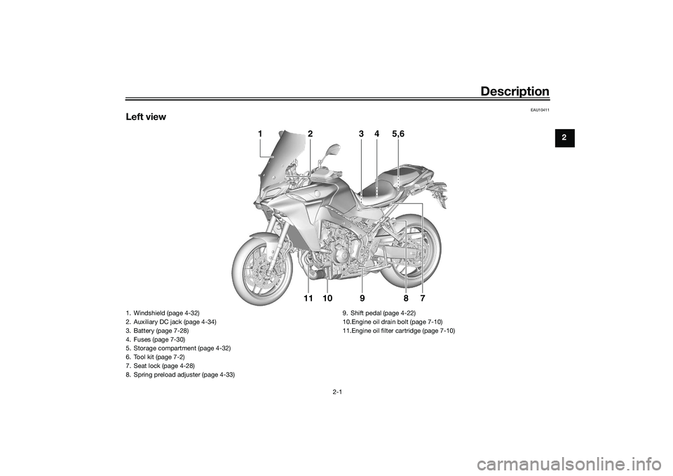
Left view
10119
7
8
3
1
2
4
5,6
1. Windshield (page 4-32)
2. Auxiliary DC jack (page 4-34)
3. Battery (page 7-28)
4. Fuses (page 7-30)
5. Storage compartment (page 4-32)
6. Tool kit (page 7-2)
7. Seat lock (page 4-28)
8. Spring preload adjuster (page 4-33) 9. Shift pedal (page 4-22)
10.Engine oil drain bolt (page 7-10)
11.Engine oil filter cartridge (page 7-10)
UBAPE0E0.book Page 1 Thursday, December 24, 2020 9:14 AM
Page 14 of 116

Description
2-2
2
EAU10421
Right view
6
74
5
2
1
3
1. Fuel tank cap (page 4-24)
2. Spring preload adjuster (page 4-33)
3. Coolant reservoir (page 7-13)
4. Engine oil level check window (page 7-10)
5. Engine oil filler cap (page 7-10)
6. Brake pedal (page 4-23)
7. Rear brake fluid reservoir (page 7-20)UBAPE0E0.book Page 2 Thursday, December 24, 2020 9:14 AM
Page 15 of 116

Description
2-3
2
EAU10431
Controls and instruments
3
1
2
4
5
6
7
8 8 8
1. Clutch lever (page 4-21)
2. Left handlebar switches (page 4-3)
3. Instrument panel (page 4-6, 4-9)
4. Front brake fluid reservoir (page 7-20)
5. Right handlebar switches (page 4-3)
6. Brake lever (page 4-22)
7. Throttle grip
8. Main switch/steering lock (page 4-2)
UBAPE0E0.book Page 3 Thursday, December 24, 2020 9:14 AM
Page 16 of 116
Special features
3-1
3
EAU92761
Cruise control systemThis model is equipped with a cruise
control system designed to maintain a
set cruising speed.
The cruise control system operates
only when riding in 4th, 5th or 6th gear
at speeds between about 50 km/h (31
mi/h) and 180 km/h (112 mi/h).
WARNING
EWA21180
Improper use of the cruise con-
trol system may result in loss of
control, which coul d lea d to an
acci dent. Do not activate the
cruise control system in heavy
traffic, poor weather con ditions,
or amon g win din g, slippery,
hilly, rou gh or gravel roa ds.
When travelin g uphill or d own-
hill, the cruise control system
may not be ab le to maintain the
set cruisin g speed .
To prevent acci dentally activat-
in g the cruise control system,
turn it off when not in use. Make
sure that the cruise control sys-
tem ind icator light “ ” is off.
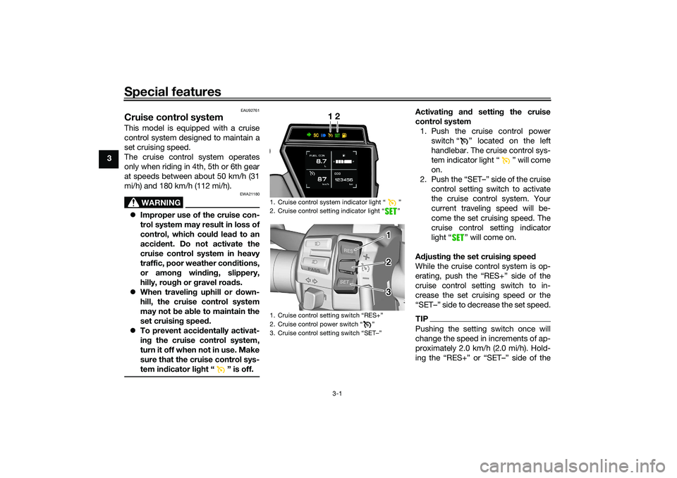
Activating and settin g the cruise
control system 1. Push the cruise control power switch “ ” located on the left
handlebar. The cruise control sys-
tem indicator light “ ” will come
on.
2. Push the “SET–” side of the cruise control setting switch to activate
the cruise control system. Your
current traveling speed will be-
come the set cruising speed. The
cruise control setting indicator
light “ ” will come on.
A djustin g the set cruisin g speed
While the cruise control system is op-
erating, push the “RES+” side of the
cruise control setting switch to in-
crease the set cruising speed or the
“SET–” side to decrease the set speed.TIPPushing the setting switch once will
change the speed in increments of ap-
proximately 2.0 km/h (2.0 mi/h). Hold-
1. Cruise control system indicator light Ž
2. Cruise control setting indicator light Ž
1.
2. Cruise control power switch Ž
3.
12
3 3 2 1 1
3 2
UBAPE0E0.book Page 1 Thursday, December 24, 2020 9:14 AM
Page 17 of 116
Special features
3-2
3
cruise control setting switch down will
increase or decrease the speed contin-
uously until the switch is released.
You can also manually increase your
traveling speed using the throttle. After
you have accelerated, you can set a
new cruising speed by pushing the
“SET–” side of the setting switch. If you
do not set a new cruising speed, when
you return the throttle grip, the vehicle
will decelerate to the previously set
cruising speed.TIPThe current cruise control speed set-
ting can be viewed on the vehicle infor-
mation displays. (See page 4-10.)Deactivatin
g the cruise control sys-
tem
Perform one of the following opera-
tions to cancel the set cruising speed.
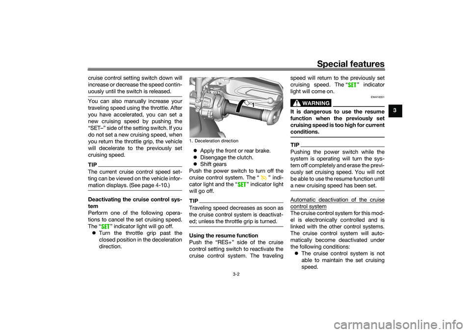
The “ ” indicator light will go off. Turn the throttle grip past the
closed position in the deceleration
direction.
Apply the front or rear brake.
Disengage the clutch.
Shift gears
Push the power switch to turn off the
cruise control system. The “ ” indi-
cator light and the “ ” indicator light
will go off.
TIPTraveling speed decreases as soon as
the cruise control system is deactivat-
ed; unless the throttle grip is turned.Usin g the resume function
Push the “RES+” side of the cruise
control setting switch to reactivate the
cruise control system. The traveling speed will return to the previously set
cruising speed. The “ ” indicator
light will come on.
WARNING
EWA16351
It is d
angerous to use the resume
function when the previously set
cruisin g speed is too hi gh for current
con ditions.TIPPushing the power switch while the
system is operating will turn the sys-
tem off completely and erase the previ-
ously set cruising speed. You will not
be able to use the resume function until
a new cruising speed has been set.Automatic deactivation of the cruisecontrol systemThe cruise control system for this mod-
el is electronically controlled and is
linked with the other control systems.
The cruise control system will auto-
matically become deactivated under
the following conditions:
The cruise control system is not
able to maintain the set cruising
speed.
1. Deceleration direction
1 1 1
UBAPE0E0.book Page 2 Thursday, December 24, 2020 9:14 AM
Page 18 of 116

Special features
3-3
3
Wheel slip or wheel spin is detect-
ed. (If the traction control system
has not been turned off, the trac-
tion control system will work.)
The start/engine stop switch is set
to the “ ” position.
The engine stalls.
The sidestand is lowered.
When traveling with a set cruising
speed, if the cruise control system is
deactivated under the above condi-
tions, the “ ” indicator light will go
off and the “ ” indicator light will
flash for 4 seconds, and then go off.
When not traveling with a set cruising
speed, if the start/engine stop switch is
set to the “ ” position, the engine
stalls, or the sidestand is lowered, then
the “ ” indicator light will go off
(the “ ” indicator light will not flash).
If the cruise control system is automat-
ically deactivated, please stop and
confirm that your vehicle is in good op-
erating condition.
Before using the cruise control system
again, activate it using the power
switch.
TIPIn some cases, the cruise control sys-
tem may not be able to maintain the set
cruising speed when the vehicle is
traveling uphill or downhill. When the vehicle is traveling up-
hill, the actual traveling speed may
become lower than the set cruis-
ing speed. If this occurs, acceler-
ate to the desired traveling speed
using the throttle.
When the vehicle is traveling
downhill, the actual traveling
speed may become higher than
the set cruising speed. If this oc-
curs, the setting switch cannot be
used to adjust the set cruising
speed. To reduce the traveling
speed, apply the brakes. When
the brakes are applied, the cruise
control system will become deac-
tivated.
EAU91323
“D-MODE”“D-MODE” is an electronically con-
trolled engine performance system.
WARNING
EWA18440
Do not chan ge the d rive mo de while
the vehicle is movin g.The “D-MODE” system consists of 4
different control maps which regulate
engine response and output, thus pro-
viding you with a selection of modes to
fit your preferences and the riding envi-
ronment.
D-MODE 1 - Sporty engine response
D-MODE 2 - Moderate engine re-
sponse
D-MODE 3 - Mild engine response
D-MODE 4 - Mild engine response and
limits engine outputTIP The current “D-MODE” setting is
shown in the MODE display. (See
page 4-13.)
The current “D-MODE” setting is
saved when the vehicle is turned
off.
UBAPE0E0.book Page 3 Thursday, December 24, 2020 9:14 AM
Page 19 of 116
Special features
3-4
3
The “D-MODE” is controlled by
the MODE switches, see page 4-4
for more information.
EAU92770
“SUS-MODE”“SUS-MODE” is an electronically con-
trolled suspension damping system,
called KYB Actimatic© Damper Sys-
tem (KADS), which automatically ad-
justs the suspension’s damping force
to suit the riding situation.
WARNING
EWA21170
Do not chan ge the suspension mod e
while the vehicle is movin g.The “SUS-MODE” system consists of
2 different control maps which regulate
suspension damping force, thus pro-
viding you with a selection of modes to
fit your preferences and the riding envi-
ronment.
SUS-MODE A-1 - Sport setting with
increased damping force, suitable for
smoother road conditions
SUS-MODE A-2 - Comfort setting with
softer damping force, suitable for
rougher road conditionsTIP The current “SUS-MODE” setting
is shown in the MODE display.
(See page 4-13.)
The current “SUS-MODE” setting
is saved when the vehicle is
turned off.
The “SUS-MODE” is controlled by
the MODE switches, see page 4-4
for more information.
UBAPE0E0.book Page 4 Thursday, December 24, 2020 9:14 AM
Page 20 of 116
Special features
3-5
3
EAU92650
“TCS-MODE”This model is equipped with adjustable
traction, slide, and lift control systems
(TCS, SCS and LIF). These are
grouped together into “TCS-MODE”.
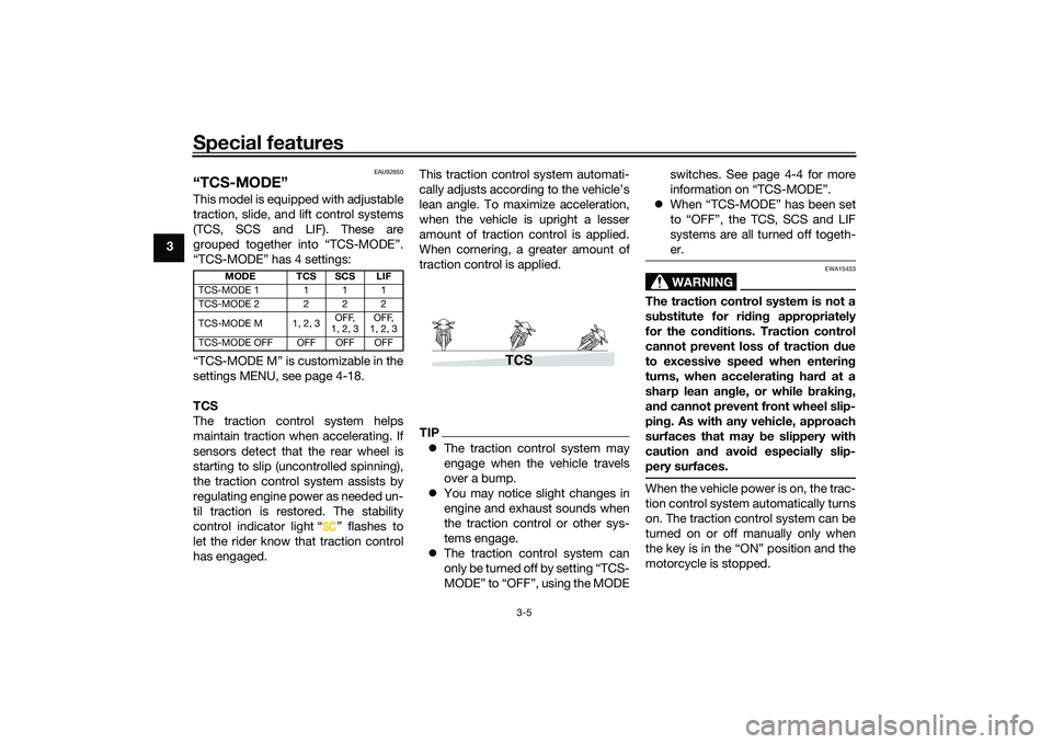
“TCS-MODE” has 4 settings:
“TCS-MODE M” is customizable in the
settings MENU, see page 4-18.
TCS
The traction control system helps
maintain traction when accelerating. If
sensors detect that the rear wheel is
starting to slip (uncontrolled spinning),
the traction control system assists by
regulating engine power as needed un-
til traction is restored. The stability
control indicator light “ ” flashes to
let the rider know that traction control
has engaged.This traction control system automati-
cally adjusts according to the vehicle’s
lean angle. To maximize acceleration,
when the vehicle is upright a lesser
amount of traction control is applied.
When cornering, a greater amount of
traction control is applied.
TIP
The traction control system may
engage when the vehicle travels
over a bump.
You may notice slight changes in
engine and exhaust sounds when
the traction control or other sys-
tems engage.
The traction control system can
only be turned off by setting “TCS-
MODE” to “OFF”, using the MODE switches. See page 4-4 for more
information on “TCS-MODE”.
When “TCS-MODE” has been set
to “OFF”, the TCS, SCS and LIF
systems are all turned off togeth-
er.
WARNING
EWA15433
The traction control system is not a
substitute for rid ing appropriately
for the con ditions. Traction control
cannot prevent loss of traction d ue
to excessive speed when entering
turns, when acceleratin g har d at a
sharp lean an gle, or while brakin g,
an d cannot prevent front wheel slip-
pin g. As with any vehicle, approach
surfaces that may be slippery with
caution an d avoi d especially slip-
pery surfaces.When the vehicle power is on, the trac-
tion control system automatically turns
on. The traction control system can be
turned on or off manually only when
the key is in the “ON” position and the
motorcycle is stopped.
MODE TCS SCS LIF
TCS-MODE 1 111
TCS-MODE 2 222
TCS-MODE M 1, 2, 3 OFF,
1, 2, 3 OFF,
1, 2, 3
TCS-MODE OFF OFF OFF OFF
TCS
UBAPE0E0.book Page 5 Thursday, December 24, 2020 9:14 AM