coolant YAMAHA TRACER 900 GT 2021 User Guide
[x] Cancel search | Manufacturer: YAMAHA, Model Year: 2021, Model line: TRACER 900 GT, Model: YAMAHA TRACER 900 GT 2021Pages: 116, PDF Size: 4.35 MB
Page 60 of 116
For your safety – pre-operation checks
5-1
5
EAU1559B
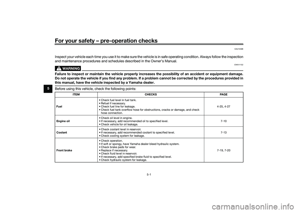
Inspect your vehicle each time you use it to make sure the vehicle is in safe operating condition. Always follow the inspection
and maintenance procedures and schedules described in the Owner’s Manual.
WARNING
EWA11152
Failure to inspect or maintain the vehicle properly increases the possibility of an acci dent or equipment damag e.
Do not operate the vehicle if you fin d any pro blem. If a pro blem cannot b e corrected b y the proce dures provi ded in
this manual, have the vehicle inspecte d b y a Yamaha dealer.Before using this vehicle, check the following points:
ITEM CHECKS PAGE
Fuel • Check fuel level in fuel tank.
• Refuel if necessary.
• Check fuel line for leakage.
• Check fuel tank overflow hose for obstructions, cracks or damage, and check
hose connection. 4-25, 4-27
En gine oil • Check oil level in engine.
• If necessary, add recommended oil to specified level.
• Check vehicle for oil leakage. 7-10
Coolant • Check coolant level in reservoir.
• If necessary, add recommended coolant to specified level.
• Check cooling system for leakage. 7-13
Front brake • Check operation.
• If soft or spongy, have Yamaha dealer bleed hydraulic system.
• Check brake pads for wear.
• Replace if necessary.
• Check fluid level in reservoir.
• If necessary, add specified brake fluid to specified level.
• Check hydraulic system for leakage. 7-19, 7-20
UBAPE0E0.book Page 1 Thursday, December 24, 2020 9:14 AM
Page 64 of 116
Operation and important rid ing points
6-2
6
EAU91411
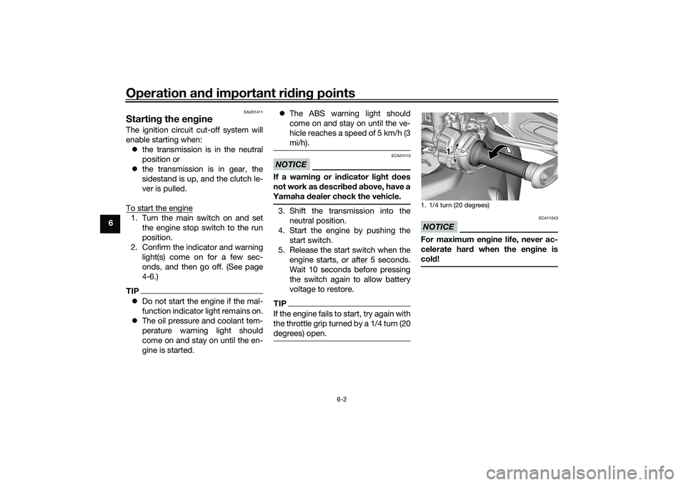
Startin g the eng ineThe ignition circuit cut-off system will
enable starting when:
the transmission is in the neutral
position or
the transmission is in gear, the
sidestand is up, and the clutch le-
ver is pulled.
To start the engine1. Turn the main switch on and set the engine stop switch to the run
position.
2. Confirm the indicator and warning light(s) come on for a few sec-
onds, and then go off. (See page
4-6.)TIPDo not start the engine if the mal-
function indicator light remains on.
The oil pressure and coolant tem-
perature warning light should
come on and stay on until the en-
gine is started.
The ABS warning light should
come on and stay on until the ve-
hicle reaches a speed of 5 km/h (3
mi/h).
NOTICE
ECA24110
If a warnin g or in dicator li ght does
not work as d escribed a bove, have a
Yamaha dealer check the vehicle.3. Shift the transmission into the
neutral position.
4. Start the engine by pushing the start switch.
5. Release the start switch when the engine starts, or after 5 seconds.
Wait 10 seconds before pressing
the switch again to allow battery
voltage to restore.TIPIf the engine fails to start, try again with
the throttle grip turned by a 1/4 turn (20
degrees) open.
NOTICE
ECA11043
For maximum en gine life, never ac-
celerate har d when the en gine is
col d!1. 1/4 turn (20 degrees)
1 1 1
UBAPE0E0.book Page 2 Thursday, December 24, 2020 9:14 AM
Page 74 of 116
Periodic maintenance an d a djustment
7-7
7
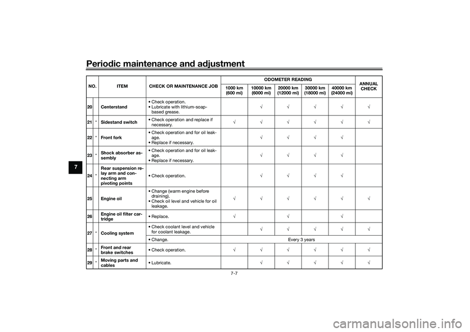
20 Centerstan d• Check operation.
• Lubricate with lithium-soap-
based grease. √√√√√
21 *Sidestan d switch • Check operation and replace if
necessary. √√√√√√
22 *Front fork • Check operation and for oil leak-
age.
• Replace if necessary. √√√√
23 *Shock a
bsor ber as-
sem bly • Check operation and for oil leak-
age.
• Replace if necessary. √√√√
24 *Rear suspension re-
lay arm an
d con-
nectin g arm
pivotin g points • Check operation.
√√√√
25 En gine oil • Change (warm engine before
draining).
• Check oil level and vehicle for oil leakage. √√√√√√
26 En
gine oil filter car-
tri dge • Replace.
√√√
27 *Coolin g system • Check coolant level and vehicle
for coolant leakage. √√√√√
• Change. Every 3 years
28 *Front an
d rear
b rake switches • Check operation.
√√√√√√
29 *Movin
g parts an d
cab les • Lubricate.
√√√√√
NO. ITEM CHECK OR MAINTENANCE JOB
ODOMETER READING
ANNUAL
CHECK
1000 k
m
(600 m i
) 10000 km
(6000 mi) 20000 km
(12000 mi) 30000 km
(18000 mi) 40000 km
(24000 mi)
UBAPE0E0.book Page 7 Thursday, December 24, 2020 9:14 AM
Page 80 of 116
Periodic maintenance an d a djustment
7-13
7
EAUS1203
CoolantThe coolant level should be checked
regularly. In addition, the coolant must
be changed at the intervals specified in
the periodic maintenance chart.TIPIf genuine Yamaha coolant is not avail-
able, use an ethylene glycol antifreeze
containing corrosion inhibitors for alu-
minum engines and mix with distilled
water at a 1:1 ratio.
EAU20097
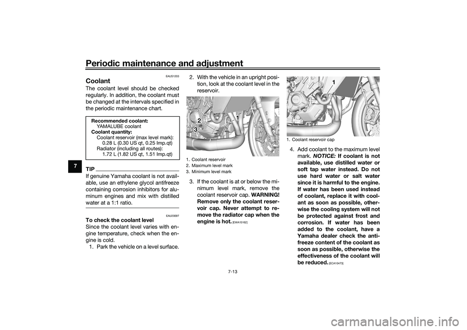
To check the coolant level
Since the coolant level varies with en-
gine temperature, check when the en-
gine is cold.
1. Park the vehicle on a level surface. 2. With the vehicle in an upright posi-
tion, look at the coolant level in the
reservoir.
3. If the coolant is at or below the mi- nimum level mark, remove the
coolant reservoir cap. WARNING!
Remove only the coolant reser-
voir cap. Never attempt to re-
move the ra diator cap when the
en gine is hot.
[EWA15162]
4. Add coolant to the maximum level
mark. NOTICE: If coolant is not
availa ble, use d istilled water or
soft tap water instead . Do not
use har d water or salt water
since it is harmful to the en gine.
If water has been used instead
of coolant, replace it with cool-
ant as soon as possi ble, other-
wise the coolin g system will not
b e protecte d a gainst frost an d
corrosion. If water has been
a dde d to the coolant, have a
Yamaha dealer check the anti-
freeze content of the coolant as
soon as possi ble, otherwise the
effectiveness of the coolant will
b e re duce d.
[ECA10473]
Recommen ded coolant:
YAMALUBE coolant
Coolant quantity: Coolant reservoir (max level mark):0.28 L (0.30 US qt, 0.25 Imp.qt)
Radiator (including all routes): 1.72 L (1.82 US qt, 1.51 Imp.qt)
1. Coolant reservoir
2. Maximum level mark
3. Minimum level mark
1 1
2 1
2
3 3
1. Coolant reservoir cap
1 1 1
UBAPE0E0.book Page 13 Thursday, December 24, 2020 9:14 AM
Page 81 of 116
Periodic maintenance an d a djustment
7-14
7
5. Install the coolant reservoir cap.
EAU33032
Chan
gin g the coolant
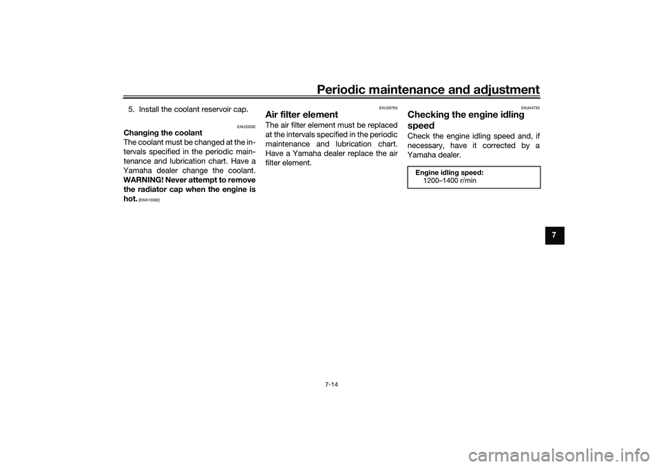
The coolant must be changed at the in-
tervals specified in the periodic main-
tenance and lubrication chart. Have a
Yamaha dealer change the coolant.
WARNING! Never attempt to remove the ra diator cap when the en gine is
hot.
[EWA10382] EAU36765
Air filter elementThe air filter element must be replaced
at the intervals specified in the periodic
maintenance and lubrication chart.
Have a Yamaha dealer replace the air
filter element.
EAU44735
Checkin
g the en gine i dlin g
spee dCheck the engine idling speed and, if
necessary, have it corrected by a
Yamaha dealer.
Engine i dlin g spee d:
1200–1400 r/min
UBAPE0E0.book Page 14 Thursday, December 24, 2020 9:14 AM
Page 103 of 116
Periodic maintenance an d a djustment
7-36
7
EAU86420
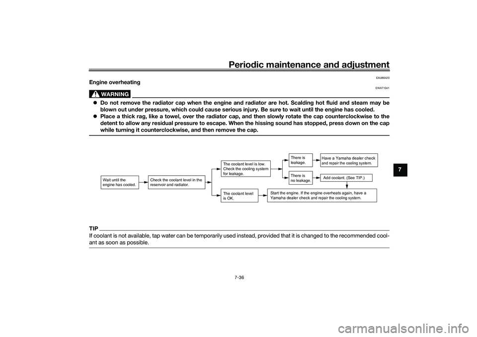
En gine overheatin g
WARNING
EWAT1041
Do not remove the ra diator cap when the en gine an d ra diator are hot. Scal din g hot flui d an d steam may be
b lown out un der pressure, which coul d cause serious injury. Be sure to wait until the en gine has coole d.
Place a thick rag , like a towel, over the ra diator cap, an d then slowly rotate the cap counterclockwise to the
d etent to allow any resi dual pressure to escape. When the hissin g soun d has stopped , press down on the cap
while turnin g it counterclockwise, an d then remove the cap.TIPIf coolant is not available, tap water can be temporarily used instead, provided that it is changed to the recommended cool-
ant as soon as possible.
Wait until the
engine has cooled.
Check the coolant level in the
reservoir and radiator.
The coolant level
is OK.The coolant level is low.
Check the cooling system
for leakage.
Have a Yamaha dealer checkand repair the cooling system.Add coolant. (See TIP.)
Start the engine. If the engine overheats again,
have a
Yamaha dealer check
and repair the cooling system.
There is
leakage.
There is
no leakage.
UBAPE0E0.book Page 36 Thursday, December 24, 2020 9:14 AM
Page 108 of 116
Specifications
9-1
9
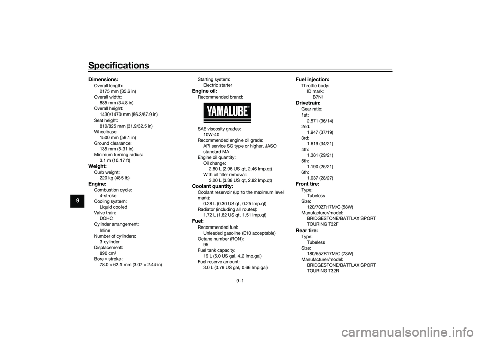
Dimensions:Overall length:2175 mm (85.6 in)
Overall width:
885 mm (34.8 in)
Overall height: 1430/1470 mm (56.3/57.9 in)
Seat height: 810/825 mm (31.9/32.5 in)
Wheelbase:
1500 mm (59.1 in)
Ground clearance: 135 mm (5.31 in)
Minimum turning radius: 3.1 m (10.17 ft)Wei ght:Curb weight:
220 kg (485 lb)Engine:Combustion cycle:
4-stroke
Cooling system: Liquid cooled
Valve train: DOHC
Cylinder arrangement:
Inline
Number of cylinders: 3-cylinder
Displacement: 890 cm³
Bore × stroke:
78.0 × 62.1 mm (3.07 × 2.44 in) Starting system:
Electric starter
Engine oil:Recommended brand:
SAE viscosity grades:
10W-40
Recommended engine oil grade:
API service SG type or higher, JASO
standard MA
Engine oil quantity:
Oil change: 2.80 L (2.96 US qt, 2.46 Imp.qt)
With oil filter removal:
3.20 L (3.38 US qt, 2.82 Imp.qt)Coolant quantity:Coolant reservoir (up to the maximum level
mark):0.28 L (0.30 US qt, 0.25 Imp.qt)
Radiator (including all routes): 1.72 L (1.82 US qt, 1.51 Imp.qt)Fuel:Recommended fuel:Unleaded gasoline (E10 acceptable)
Octane number (RON): 95
Fuel tank capacity:
19 L (5.0 US gal, 4.2 Imp.gal)
Fuel reserve amount: 3.0 L (0.79 US gal, 0.66 Imp.gal)
Fuel injection:Throttle body:ID mark: B7N1Drivetrain:Gear ratio:
1st:2.571 (36/14)
2nd:
1.947 (37/19)
3rd: 1.619 (34/21)
4th: 1.381 (29/21)
5th:
1.190 (25/21)
6th: 1.037 (28/27)Front tire:Type:
Tubeless
Size: 120/70ZR17M/C (58W)
Manufacturer/model: BRIDGESTONE/BATTLAX SPORT
TOURING T32FRear tire:Type:
Tubeless
Size: 180/55ZR17M/C (73W)
Manufacturer/model: BRIDGESTONE/BATTLAX SPORT
TOURING T32R
UBAPE0E0.book Page 1 Thursday, December 24, 2020 9:14 AM
Page 113 of 116
11-1
11
Index
AABS warning light ................................... 4-7
Air filter element.................................... 7-14
Auxiliary DC connector ......................... 4-35
Auxiliary DC jack .................................. 4-34
Auxiliary system warning light ................ 4-9BBattery .................................................. 7-28
BC........................................................... 3-7
Brake and clutch levers, checking and
lubricating........................................... 7-25
Brake and shift pedals, checking and
lubricating........................................... 7-25
Brake control system (BC).................... 4-23
Brake fluid, changing............................ 7-21
Brake fluid level, checking.................... 7-20
Brake lever............................................ 4-22
Brake lever free play, checking ............ 7-18
Brake light switches ............................. 7-19
Brake pedal .......................................... 4-23CCables, checking and lubricating ......... 7-24
Canister ................................................ 7-10
Care ........................................................ 8-1
Catalytic converter ............................... 4-27
Centerstand and sidestand, checking
and lubricating ................................... 7-26
Clutch lever........................................... 4-21
Clutch lever free play, adjusting ........... 7-18
Coolant ................................................. 7-13
Cruise control indicator lights................. 4-6
Cruise control switches .......................... 4-4
Cruise control system............................. 3-1
DData recording, vehicle ........................ 10-2
Diagnostic connector ........................... 10-2
Dimmer/Pass switch .............................. 4-3
Display, menu screen........................... 4-17
Displays.................................................. 4-9
D-MODE................................................. 3-3
Drive chain, cleaning and lubricating ... 7-23
Drive chain slack .................................. 7-22EEngine break-in ...................................... 6-1
Engine idling speed, checking ............. 7-14
Engine oil.............................................. 7-10
Engine overheating .............................. 7-36
Engine serial number ........................... 10-1FFront and rear brake pads, checking ... 7-19
Front fork, checking ............................. 7-27
Fuel ...................................................... 4-25
Fuel consumption, tips for reducing ...... 6-4
Fuel level warning light........................... 4-6
Fuel tank cap........................................ 4-24
Fuel tank overflow hose ....................... 4-27
Fuses, replacing ................................... 7-30HHandlebar position, adjusting .............. 4-32
Handlebar switches ............................... 4-3
Hazard switch ........................................ 4-4
High beam indicator light ....................... 4-6
Horn switch ............................................ 4-4IIdentification numbers ......................... 10-1
Ignition circuit cut-off system .............. 4-36
Immobilizer system ................................ 4-1 Immobilizer system indicator light .......... 4-8
Indicator lights and warning lights .......... 4-6
LLicense plate light bulb, replacing ........ 7-32
Luggage strap holders.......................... 4-34MMain switch/steering lock ....................... 4-2
Maintenance and lubrication, periodic ... 7-5
Maintenance, emission control
system .................................................. 7-3
Malfunction indicator light (MIL) ............. 4-7
Matte color, caution................................ 8-1
Model label ........................................... 10-1NNeutral indicator light ............................. 4-6OOil pressure and Coolant temperature warning light ......................................... 4-8PParking.................................................... 6-5
Part locations.......................................... 2-1QQSS ........................................................ 3-6RRider footrest position, adjusting ......... 4-31
Rider seat height, adjusting .................. 4-29SSafety information................................... 1-1
Seats ..................................................... 4-28
Shifting.................................................... 6-3
Shift pedal............................................. 4-22
Sidestand.............................................. 4-35
Spark plugs, checking ............................ 7-9
Special features ...................................... 3-1
UBAPE0E0.book Page 1 Thursday, December 24, 2020 9:14 AM