wheel YAMAHA TRACER 900 GT 2021 User Guide
[x] Cancel search | Manufacturer: YAMAHA, Model Year: 2021, Model line: TRACER 900 GT, Model: YAMAHA TRACER 900 GT 2021Pages: 116, PDF Size: 4.35 MB
Page 30 of 116
Instrument and control functions
4-8
4
WARNING
EWA21120
If the ABS warnin g lig ht does not
turn off after reachin g 5 km/h (3
mi/h), or if the warnin g li ght comes
on while rid ing:
Use extra caution to avoi d pos-
si ble wheel lock d uring emer-
g ency brakin g.
Have a Yamaha dealer check
the vehicle as soon as possi ble.
EAU92710
Immo bilizer system in dicator
li g ht “ ”
When the main switch is turned off and
30 seconds have passed, the indicator
light will flash steadily to indicate the
immobilizer system is enabled. After 24
hours have passed, the indicator light
will stop flashing, however the immobi-
lizer system is still enabled.TIPWhen the vehicle is turned on, this light
should come on for a few seconds and
then go off. If the light does not come
on, or if the light remains on, have a
Yamaha dealer check the vehicle.
Transpon der interference
If the immobilizer system indicator light
flashes in the pattern, slowly 5 times
then quickly 2 times, this could be
caused by transponder interference. If
this occurs, try the following. 1. Make sure there are no other im- mobilizer keys close to the main
switch.
2. Use the code re-registering key to start the engine.
3. If the engine starts, turn it off, and try starting the engine with the
standard keys.
4. If one or both of the standard keys do not start the engine, take the
vehicle and all 3 keys to a Yamaha
dealer to have the standard keys
re-registered.
EAU92720
Sta bility control in dicator li ght “ ”
This indicator light flashes when the
TCS, SCS, or LIF systems engage
while riding. When “TCS-MODE” is set
to “OFF”, the indicator will come on.
TIPWhen the vehicle is turned on, this light
should come on for a few seconds and
then go off. If the light does not come
on, or if the light remains on, have a
Yamaha dealer check the vehicle.NOTICE
ECA27221
When turnin g the main switch on,
avoi d any movement or vi bration of
the vehicle as it may interfere with
the initialization of the IMU. If this
occurs, the TCS system will not op-
erate an d the “TCS-MODE” display
will rea d “OFF” until the IMU can ini-
tialize.
EAU92751
Oil pressure an d Coolant tempera-
ture warnin g lig ht “ ”
This warning light comes on if the en-
gine oil pressure is low or if the coolant
temperature is high. If this occurs, stop
the engine immediately.TIP When the vehicle is first turned on,
this light should come on until the
engine is started.
UBAPE0E0.book Page 8 Thursday, December 24, 2020 9:14 AM
Page 33 of 116
Instrument and control functions
4-11
4
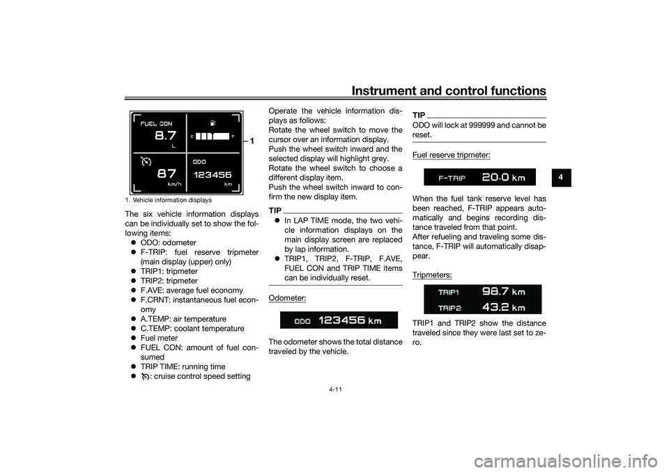
The six vehicle information displays
can be individually set to show the fol-
lowing items: ODO: odometer
F-TRIP: fuel reserve tripmeter
(main display (upper) only)
TRIP1: tripmeter
TRIP2: tripmeter
F.AVE: average fuel economy
F.CRNT: instantaneous fuel econ-
omy
A.TEMP: air temperature
C.TEMP: coolant temperature
Fuel meter
FUEL CON: amount of fuel con-
sumed
TRIP TIME: running time
: cruise control speed setting Operate the vehicle information dis-
plays as follows:
Rotate the wheel switch to move the
cursor over an information display.
Push the wheel switch inward and the
selected display will highlight grey.
Rotate the wheel switch to choose a
different display item.
Push the wheel switch inward to con-
firm the new display item.
TIP
In LAP TIME mode, the two vehi-
cle information displays on the
main display screen are replaced
by lap information.
TRIP1, TRIP2, F-TRIP, F.AVE,
FUEL CON and TRIP TIME items
can be individually reset.Odometer:The odometer shows the total distance
traveled by the vehicle.
TIPODO will lock at 999999 and cannot be
reset.Fuel reserve tripmeter:When the fuel tank reserve level has
been reached, F-TRIP appears auto-
matically and begins recording dis-
tance traveled from that point.
After refueling and traveling some dis-
tance, F-TRIP will automatically disap-
pear.
Tripmeters:TRIP1 and TRIP2 sh ow the distance
traveled since they were last set to ze-
ro.
1. Vehicle information displays
1
UBAPE0E0.book Page 11 Thursday, December 24, 2020 9:14 AM
Page 35 of 116
Instrument and control functions
4-13
4
Displays how much fuel has been con-
sumed since the trip meter was last re-
set.
TIPThe instantaneous fuel consumption
function should be used for general
reference only. Do not use this figure to
estimate the distance that can be trav-
eled on the current tank of fuel.Trip time:Displays engine running time.
Cruise control speed setting:Displays the selected speed setting for
the cruise control system. To adjust
this speed setting, see page 3-1 for an
explanation of the cruise control sys-
tem. To reset information display items (if
able):1. Rotate the wheel switch to high-
light one of the six vehicle informa-
tion displays.
2. Press the wheel switch inward to select the information display.
3. Rotate the wheel switch to select the desired information display
item.
4. Press and hold the wheel switch inward until the display item is re-
set.
Transmission gear display
This shows which gear the transmis-
sion is in. This model has 6 gears and a
neutral position. The neutral position is
indicated by the neutral indicator
light “ ” and by the transmission gear
display “ ”. MODE
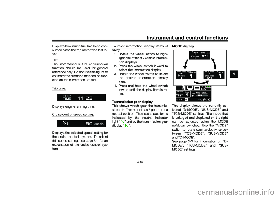
display
This display shows the currently se-
lected “D-MODE”, “SUS-MODE” and
“TCS-MODE” settings. The mode that
is enlarged and displayed on the right
can be adjusted using the MODE
up/down switches. Use the “MODE”
switch to rotate counterclockwise be-
tween “TCS-MODE”, “SUS-MODE”
and “D-MODE”.
See page 3-3 for information on “D-
MODE”, “TCS-MODE” and “SUS-
MODE” settings.
UBAPE0E0.book Page 13 Thursday, December 24, 2020 9:14 AM
Page 36 of 116
Instrument and control functions
4-14
4
TIP When the malfunction indicator
light “ ”, the auxiliary system
warning “ ”, or the coolant tem-
perature warning “ ” are on, “D-
MODE”, “SUS-MODE” and “TCS-
MODE” cannot be adjusted.
When the SCU trouble
warning “ ” is on, “SUS-MODE”
cannot be adjusted.
The previously selected modes
will be displayed when the vehicle
power is turned on.To turn off the traction control system,
select “TCS-MODE” with the “MODE”
switch, then push and hold the MODE
up switch until “OFF” is displayed. To
turn TCS back on, press the MODE
down switch (“TCS-MODE” will return
to its previous setting).TIPWhen “TCS-MODE” has been set
to “OFF”, the TCS, SCS and LIF
systems are all turned off togeth-
er.
The “TCS-MODE OFF” and “TCS-
MODE M” settings can only be se-
lected while the vehicle is
stopped.
Clock
The clock uses a 12-hour time system.
See page 4-20 to set the clock.
Quick shift in dicator “QS”
When able to shift, the respective QS or turns green.
When unable to shift, QS is
white.
If the QS function is turned OFF, QS itself is not displayed.
The QS functions can be turned on or
off in the setting MENU. See page
4-18.TIPThe upshift and downshift functions
are independent and can be activated
separately.
For more information on the QS sys-
Settin g MENU icon “ ”
Choose this icon and push the wheel
switch to access the settings MENU.
(See page 4-17.)
Grip warmer in dicator
The grip warmers can be used when
the engine is running. There are 10
temperature levels. When activated,
the indicator will display the tempera-
ture level from 1 (lowest) to 10 (high-
est).
To activate the grip warmer, use the
wheel switch to highlight the grip
warmer display with the cursor.
Press the wheel switch inward to se-
lect the grip warmer function.
Once selected, rotate the wheel switch
up and down to adjust the temperature
level.
Press the wheel switch inward to con-
firm the temperature level and exit the
grip warmer function.NOTICE
ECA17932
Be sure to wear gloves when
usin g the g rip warmers.
Do not use the grip warmers in
warm weather.
UBAPE0E0.book Page 14 Thursday, December 24, 2020 9:14 AM
Page 37 of 116
Instrument and control functions
4-15
4
If the han dle bar grip or throttle
g rip becomes worn or dam-
a g ed , stop usin g the g rip warm-
ers an d replace the grips.
Seat heater in dicator (if equipped )
The seat heater can be used when the
engine is running. There are 10 temper-
ature levels. When activated, the indi-
cator will display the temperature level
from 1 (lowest) to 10 (highest).
To activate the seat heater, use the
wheel switch to highlight the seat heat-
er display with the cursor.
Press the wheel switch inward to se-
lect the seat heater function.
Once selected, rotate the wheel switch
up and down to adjust the temperature
level.
Press the wheel switch inward to con-
firm the temperature level and exit the
seat heater function.NOTICE
ECA25721
Be sure to wear protective
clothin g that covers your hip
an d le gs when usin g the seat
heater.
Do not use the seat heater in
warm weather.
If the seat b ecomes worn or
d amag ed , stop usin g the seat
heater an d replace the seat.
The function of the wheel switch can
be locked into grip warmer/seat heater
mode by pressing and holding the
wheel switch inward while the grip
warmer indicator or the seat heater in-
dicator is highlighted by the cursor.
In this mode, the temperature levels
can be instantly adjusted by rotating
the wheel switch up/down.
While in this mode, press the wheel
switch inward to toggle between the
grip warmer and seat heater functions.
To exit this mode and return the wheel
switch to its normal functionality, press
and hold the wheel switch inward.TIPThe current grip warmer/seat heater
settings are saved when the vehicle is
turned off.
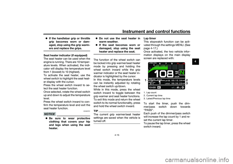
Lap timer
This stopwatch function can be acti-
vated through the settings MENU. (See
page 4-17.)
Once activated, the two vehicle infor-
mation displays on the main display
screen are replaced with:
To start the timer, push the dim-
mer/pass switch down towards
“PASS”.
Each push of the dimmer/pass switch
will increase the lap count by 1 and re-
set the current lap timer.
To pause the lap timer, press the wheel
switch inward.1. Lap count
2. Current lap time
3. Latest/Previous lap time
LAP
02
LATEST
00:12.3 4
00:3 0.23
2
1
3
UBAPE0E0.book Page 15 Thursday, December 24, 2020 9:14 AM
Page 39 of 116
Instrument and control functions
4-17
4
EAU92793
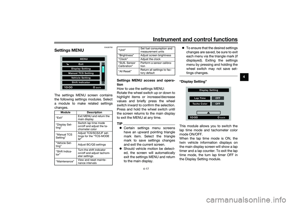
Settin gs MENUThe settings MENU screen contains
the following settings modules. Select
a module to make related settings
changes. Settin
gs MENU access an d opera-
tion
How to use the settings MENU:
Rotate the wheel switch up or down to
highlight items or increase/decrease
values and briefly press the wheel
switch inward to confirm the selection.
Press and hold the wheel switch until
the screen returns to the main display
to exit the MENU at any time.
TIP Certain settings menu screens
have an upward pointing triangle
mark item. Select the triangle
mark to save settings changes
and exit the current screen.
Should vehicle motion be detect-
ed, the screen will automatically
exit the settings MENU and return
to the main display.
To ensure that the desired settings
changes are saved, be sure to exit
each menu via the triangle mark (if
displayed). Exiting the settings
menu by pressing and holding the
wheel switch may not save set-
tings changes.
“Display Settin g”
This module allows you to switch the
lap time mode and tachometer color
mode ON/OFF.
When the lap time mode is ON, the
twin vehicle information displays on
the main display screen will show a lap
timer and a lap counter. To exit the lap
time mode, the turn lap timer OFF in
the Display Setting module.
Mo dule Description
“Exit” Exit MENU and return the
main display
“Display Set-
ting” Switch lap time mode
on/off and adjust the ta-
chometer color
“Manual TCS
Setting” Adjust TCS/SCS/LIF set-
tings for the “TCS-MODE
M”
“Vehicle Set-
ting” Adjust BC/QS settings
“Shift Indica-
tor” Turn the shift indicator
on/off and adjust tachom-
eter settings
“Maintenance” View and reset mainte-
nance intervals
Display S
etting
Exit
Manual TCS S ettingVehicle S ettingShift Indicator
km/h
MENU
Set fuel consumption and
measurement units
Adjust screen brightness
Adjust the clock
CalibrationŽ Perform a sensor calibra-
tion
Return all settings to fac-
tory default
Lap Time OFFTacho Color OFF
km/h
Display Setting
UBAPE0E0.book Page 17 Thursday, December 24, 2020 9:14 AM
Page 40 of 116
Instrument and control functions
4-18
4 To change the tachometer to color mo-
de, select ON.
“Manual TCS Settin
g”
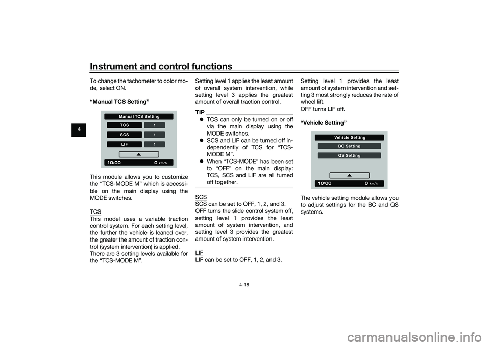
This module allows you to customize
the “TCS-MODE M” which is accessi-
ble on the main display using the
MODE switches.
TCS
This model uses a variable traction
control system. For each setting level,
the further the vehicle is leaned over,
the greater the amount of traction con-
trol (system intervention) is applied.
There are 3 setting levels available for
the “TCS-MODE M”. Setting level 1 applies the least amount
of overall system intervention, while
setting level 3 applies the greatest
amount of overall traction control.
TIP
TCS can only be turned on or off
via the main display using the
MODE switches.
SCS and LIF can be turned off in-
dependently of TCS for “TCS-
MODE M”.
When “TCS-MODE” has been set
to “OFF” on the main display:
TCS, SCS and LIF are all turned
off together.SCSSCS can be set to OFF, 1, 2, and 3.
OFF turns the slide control system off,
setting level 1 provides the least
amount of system intervention, and
setting level 3 provides the greatest
amount of system intervention.
LIFLIF can be set to OFF, 1, 2, and 3. Setting level 1 provides the least
amount of system intervention and set-
ting 3 most strongly reduces the rate of
wheel lift.
OFF turns LIF off.
“Vehicle Setting
”
The vehicle setting module allows you
to adjust settings for the BC and QS
systems.
TCS 1SC S 1LIF 1
km/h
Manual TCS Setting
BC SettingQS S etting
km/h
Vehicle Setting
UBAPE0E0.book Page 18 Thursday, December 24, 2020 9:14 AM
Page 41 of 116
Instrument and control functions
4-19
4
BC
The brake control system has two set-
tings, BC1 and BC2. Select BC1 when
only standard ABS is desired. Select
BC2 to have the brake control system
further regulate brake pressure while
cornering to suppress lateral wheel
slip.TIPFor skilled riders and when riding at the
track, due to varying conditions, the
BC2 brake system may engage sooner
than expected relative to your desired
cornering speed or intended cornering
line.
QSThe quick shift system indicators are
divided into QS and QS sections.
QS and QS are not linked and
can be independently turned on or off.
QS can be set to ON or OFF.
OFF turns the respective upshift or
downshift function off, and the clutch
lever must then be used when shifting
in that direction.TIPIf the QSS setting cannot be changed:
turn the engine off with the gear posi-
tion set to neutral, then change the set-
ting.
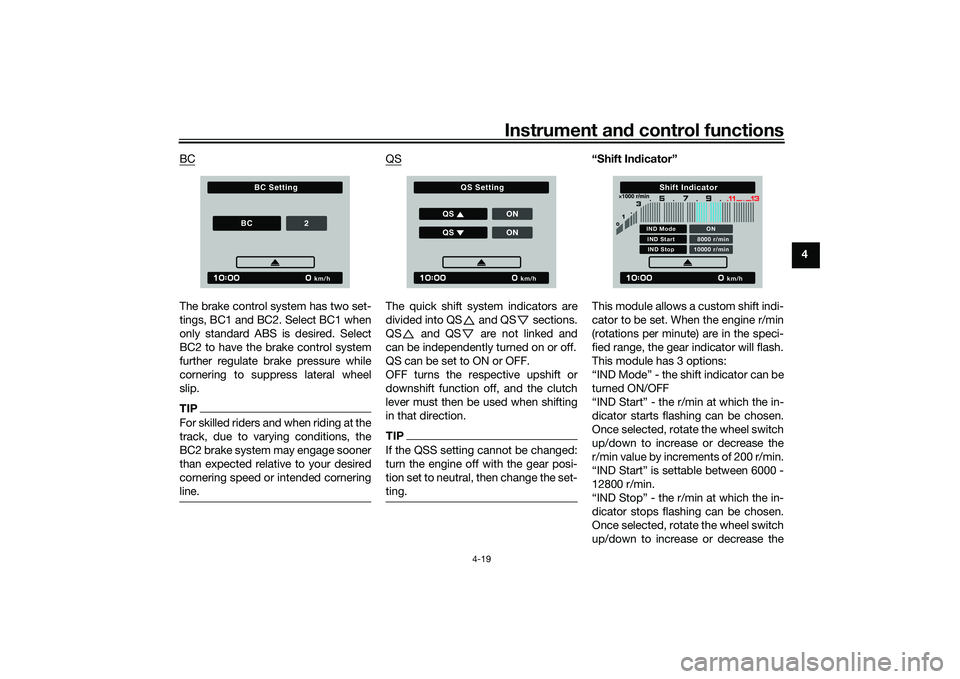
“Shift In
dicator”
This module allows a custom shift indi-
cator to be set. When the engine r/min
(rotations per minute) are in the speci-
fied range, the gear indicator will flash.
This module has 3 options:
“IND Mode” - the shift indicator can be
turned ON/OFF
“IND Start” - the r/min at which the in-
dicator starts flashing can be chosen.
Once selected, rotate the wheel switch
up/down to increase or decrease the
r/min value by increments of 200 r/min.
“IND Start” is settable between 6000 -
12800 r/min.
“IND Stop” - the r/min at which the in-
dicator stops flashing can be chosen.
Once selected, rotate the wheel switch
up/down to increase or decrease the
km/h
BC Setting
BC
2
km/h
QS Setting
Q S ONQS ON
km/h
Shift Indicator
IND Mode ONIND Start 8000 r/minIND Stop 10000 r/min
UBAPE0E0.book Page 19 Thursday, December 24, 2020 9:14 AM
Page 42 of 116
Instrument and control functions
4-20
4 r/min value by increments of 200 r/min.
“IND Stop” is settable between 6200 -
13000 r/min.
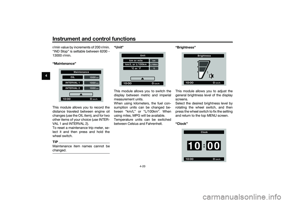
“Maintenance”
This module allows you to record the
distance traveled between engine oil
changes (use the OIL item), and for two
other items of your choice (use INTER-
VAL 1 and INTERVAL 2).
To reset a maintenance trip meter, se-
lect it and then press and hold the
wheel switch.
TIPMaintenance item names cannot be
changed.
“Unit”
This module allows you to switch the
display between metric and imperial
measurement units.
When using kilometers, the fuel con-
sumption units can be changed be-
tween “km/L” or “L/100km”. When
using miles, MPG will be available.
Temperature units can be switched
between Celsius and Fahrenheit. “Brig
htness”
This module allows you to adjust the
general brightness level of the display
screens.
Select the desired brightness level by
rotating the wheel switch, and then
press the wheel switch to fix the setting
and return to the top MENU screen.
“Clock”
OIL
INTERVAL 1INTERVAL 2 1000
km/h
km
1000
km
1000
km
Maintenance
km or mile
kmL/100km°C
km/L or L/100km
°C or °F
km/h
Unit
km/h
Brightness
1
km/h
Clock
0010
UBAPE0E0.book Page 20 Thursday, December 24, 2020 9:14 AM
Page 43 of 116
Instrument and control functions
4-21
4
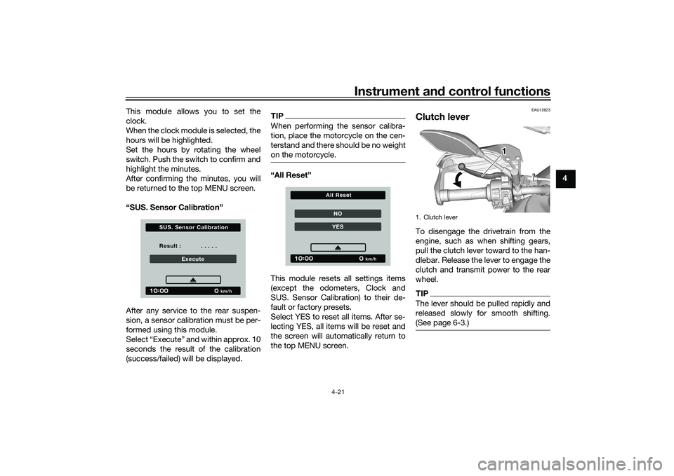
This module allows you to set the
clock.
When the clock module is selected, the
hours will be highlighted.
Set the hours by rotating the wheel
switch. Push the switch to confirm and
highlight the minutes.
After confirming the minutes, you will
be returned to the top MENU screen.
“SUS. Sensor Cali
bration”
After any service to the rear suspen-
sion, a sensor calibration must be per-
formed using this module.
Select “Execute” and within approx. 10
seconds the result of the calibration
(success/failed) will be displayed.
TIPWhen performing the sensor calibra-
tion, place the motorcycle on the cen-
terstand and there should be no weight
on the motorcycle.“All Reset”
This module resets all settings items
(except the odometers, Clock and
SUS. Sensor Calibration) to their de-
fault or factory presets.
Select YES to reset all items. After se-
lecting YES, all items will be reset and
the screen will automatically return to
the top MENU screen.
EAU12823
Clutch leverTo disengage the drivetrain from the
engine, such as when shifting gears,
pull the clutch lever toward to the han-
dlebar. Release the lever to engage the
clutch and transmit power to the rear
wheel.TIPThe lever should be pulled rapidly and
released slowly for smooth shifting.
(See page 6-3.)
Result : . . . . .
Execute
km/h
S U S. S ensor Calibration
NOYES
km/h
All Reset
1. Clutch lever
111
UBAPE0E0.book Page 21 Thursday, December 24, 2020 9:14 AM