key YAMAHA TRACER 900 GT 2021 Owners Manual
[x] Cancel search | Manufacturer: YAMAHA, Model Year: 2021, Model line: TRACER 900 GT, Model: YAMAHA TRACER 900 GT 2021Pages: 116, PDF Size: 4.35 MB
Page 4 of 116
Important manual information
EAU10134
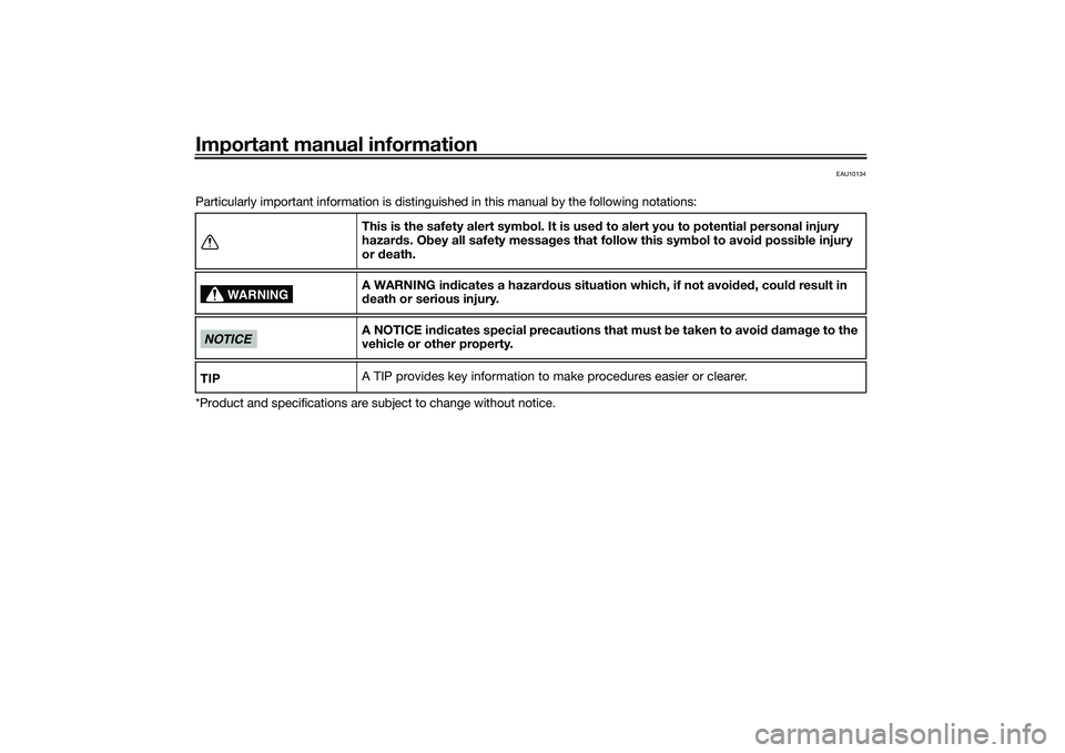
Particularly important information is distinguished in this manual by the following notations:
*Product and specifications are subject to change without notice.This is the safety alert sym
bol. It is use d to alert you to potential personal injury
hazar ds. Ob ey all safety messa ges that follow this sym bol to avoi d possi ble injury
or death.
A WARNING in dicates a hazar dous situation which, if not avoid ed , coul d result in
d eath or serious injury.
A NOTICE in dicates special precautions that must b e taken to avoid d ama ge to the
vehicle or other property.
A TIP provides key information to make procedures easier or clearer.
WARNING
NOTICETIP
UBAPE0E0.book Page 1 Thursday, December 24, 2020 9:14 AM
Page 20 of 116
Special features
3-5
3
EAU92650
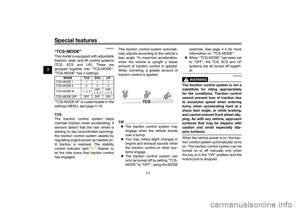
“TCS-MODE”This model is equipped with adjustable
traction, slide, and lift control systems
(TCS, SCS and LIF). These are
grouped together into “TCS-MODE”.
“TCS-MODE” has 4 settings:
“TCS-MODE M” is customizable in the
settings MENU, see page 4-18.
TCS
The traction control system helps
maintain traction when accelerating. If
sensors detect that the rear wheel is
starting to slip (uncontrolled spinning),
the traction control system assists by
regulating engine power as needed un-
til traction is restored. The stability
control indicator light “ ” flashes to
let the rider know that traction control
has engaged.This traction control system automati-
cally adjusts according to the vehicle’s
lean angle. To maximize acceleration,
when the vehicle is upright a lesser
amount of traction control is applied.
When cornering, a greater amount of
traction control is applied.
TIP
The traction control system may
engage when the vehicle travels
over a bump.
You may notice slight changes in
engine and exhaust sounds when
the traction control or other sys-
tems engage.
The traction control system can
only be turned off by setting “TCS-
MODE” to “OFF”, using the MODE switches. See page 4-4 for more
information on “TCS-MODE”.
When “TCS-MODE” has been set
to “OFF”, the TCS, SCS and LIF
systems are all turned off togeth-
er.
WARNING
EWA15433
The traction control system is not a
substitute for rid ing appropriately
for the con ditions. Traction control
cannot prevent loss of traction d ue
to excessive speed when entering
turns, when acceleratin g har d at a
sharp lean an gle, or while brakin g,
an d cannot prevent front wheel slip-
pin g. As with any vehicle, approach
surfaces that may be slippery with
caution an d avoi d especially slip-
pery surfaces.When the vehicle power is on, the trac-
tion control system automatically turns
on. The traction control system can be
turned on or off manually only when
the key is in the “ON” position and the
motorcycle is stopped.
MODE TCS SCS LIF
TCS-MODE 1 111
TCS-MODE 2 222
TCS-MODE M 1, 2, 3 OFF,
1, 2, 3 OFF,
1, 2, 3
TCS-MODE OFF OFF OFF OFF
TCS
UBAPE0E0.book Page 5 Thursday, December 24, 2020 9:14 AM
Page 23 of 116
Instrument and control functions
4-1
4
EAU1097B
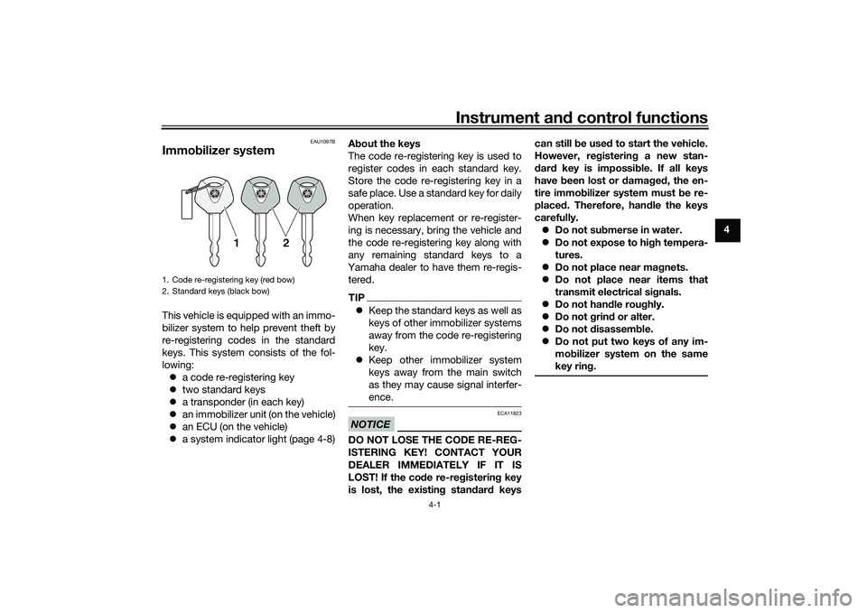
Immo bilizer systemThis vehicle is equipped with an immo-
bilizer system to help prevent theft by
re-registering codes in the standard
keys. This system consists of the fol-
lowing:
a code re-registering key
two standard keys
a transponder (in each key)
an immobilizer unit (on the vehicle)
an ECU (on the vehicle)
a system indicator light (page 4-8) A
bout the keys
The code re-registering key is used to
register codes in each standard key.
Store the code re-registering key in a
safe place. Use a standard key for daily
operation.
When key replacement or re-register-
ing is necessary, bring the vehicle and
the code re-registering key along with
any remaining standard keys to a
Yamaha dealer to have them re-regis-
tered.
TIP Keep the standard keys as well as
keys of other immobilizer systems
away from the code re-registering
key.
Keep other immobilizer system
keys away from the main switch
as they may cause signal interfer-
ence.NOTICE
ECA11823
DO NOT LOSE THE CODE RE-REG-
ISTERING KEY! CONTACT YOUR
DEALER IMMEDIATELY IF IT IS
LOST! If the co de re-reg istering key
is lost, the existin g stan dar d keys can still
be used to start the vehicle.
However, re gisterin g a new stan-
d ar d key is impossi ble. If all keys
have been lost or damag ed , the en-
tire immo bilizer system must be re-
placed . Therefore, han dle the keys
carefully. Do not su bmerse in water.
Do not expose to hi gh tempera-
tures.
Do not place near mag nets.
Do not place near items that
transmit electrical sig nals.
Do not han dle rou ghly.
Do not grin d or alter.
Do not disassem ble.
Do not put two keys of any im-
mo bilizer system on the same
key rin g.
1. Code re-registering key (red bow)
2. Standard keys (black bow)
UBAPE0E0.book Page 1 Thursday, December 24, 2020 9:14 AM
Page 24 of 116
Instrument and control functions
4-2
4
EAU10474
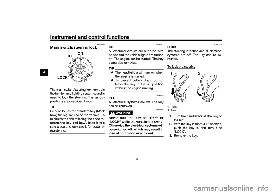
Main switch/steerin g lockThe main switch/steering lock controls
the ignition and lighting systems, and is
used to lock the steering. The various
positions are described below.TIPBe sure to use the standard key (black
bow) for regular use of the vehicle. To
minimize the risk of losing the code re-
registering key (red bow), keep it in a
safe place and only use it for code re-
registering.
EAU84031
ON
All electrical circuits are supplied with
power and the vehicle lights are turned
on. The engine can be started. The key
cannot be removed.TIP The headlight(s) will turn on when
the engine is started.
To prevent battery drain, do not
leave the key in the on position
without the engine running.
EAU10662
OFF
All electrical systems are off. The key
can be removed.
WARNING
EWA10062
Never turn the key to “OFF” or
“LOCK” while the vehicle is movin g.
Otherwise the electrical systems will
b e switche d off, which may result in
loss of control or an acci dent.
EAU73800
LOCK
The steering is locked and all electrical
systems are off. The key can be re-
moved.
To lock the steering1. Turn the handlebars all the way to
the left.
2. With the key in the “OFF” position, push the key in and turn it to
“LOCK”.
3. Remove the key.
ON
OFF
LOCK
1. Push.
2. Turn.12
UBAPE0E0.book Page 2 Thursday, December 24, 2020 9:14 AM
Page 25 of 116
Instrument and control functions
4-3
4
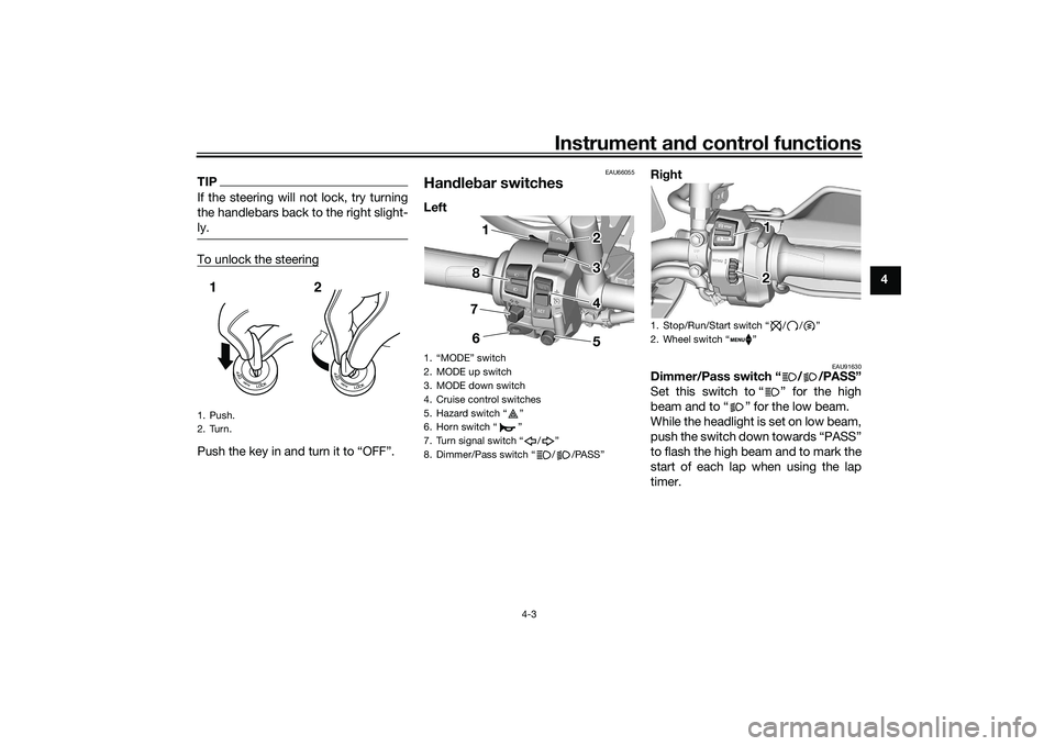
TIPIf the steering will not lock, try turning
the handlebars back to the right slight-
ly.To unlock the steeringPush the key in and turn it to “OFF”.
EAU66055
Han dle bar switchesLeft Ri
ght
EAU91630
Dimmer/Pass switch “ / /PASS”
Set this switch to “ ” for the high
beam and to “ ” for the low beam.
While the headlight is set on low beam,
push the switch down towards “PASS”
to flash the high beam and to mark the
start of each lap when using the lap
timer.
1. Push.
2. Turn.12
1.
2. MODE up switch
3. MODE down switch
4. Cruise control switches
5. Hazard switch Ž
6. Horn switch Ž
7. Turn signal switch / Ž
8. Dimmer/Pass switch / /PASSŽ
1 1 1
8 8 2 2
3 3
4 4
5
6
7
1. Stop/Run/Start switch / / Ž
2. Wheel switch Ž
11122
UBAPE0E0.book Page 3 Thursday, December 24, 2020 9:14 AM
Page 30 of 116
Instrument and control functions
4-8
4
WARNING
EWA21120
If the ABS warnin g lig ht does not
turn off after reachin g 5 km/h (3
mi/h), or if the warnin g li ght comes
on while rid ing:
Use extra caution to avoi d pos-
si ble wheel lock d uring emer-
g ency brakin g.
Have a Yamaha dealer check
the vehicle as soon as possi ble.
EAU92710
Immo bilizer system in dicator
li g ht “ ”
When the main switch is turned off and
30 seconds have passed, the indicator
light will flash steadily to indicate the
immobilizer system is enabled. After 24
hours have passed, the indicator light
will stop flashing, however the immobi-
lizer system is still enabled.TIPWhen the vehicle is turned on, this light
should come on for a few seconds and
then go off. If the light does not come
on, or if the light remains on, have a
Yamaha dealer check the vehicle.
Transpon der interference
If the immobilizer system indicator light
flashes in the pattern, slowly 5 times
then quickly 2 times, this could be
caused by transponder interference. If
this occurs, try the following. 1. Make sure there are no other im- mobilizer keys close to the main
switch.
2. Use the code re-registering key to start the engine.
3. If the engine starts, turn it off, and try starting the engine with the
standard keys.
4. If one or both of the standard keys do not start the engine, take the
vehicle and all 3 keys to a Yamaha
dealer to have the standard keys
re-registered.
EAU92720
Sta bility control in dicator li ght “ ”
This indicator light flashes when the
TCS, SCS, or LIF systems engage
while riding. When “TCS-MODE” is set
to “OFF”, the indicator will come on.
TIPWhen the vehicle is turned on, this light
should come on for a few seconds and
then go off. If the light does not come
on, or if the light remains on, have a
Yamaha dealer check the vehicle.NOTICE
ECA27221
When turnin g the main switch on,
avoi d any movement or vi bration of
the vehicle as it may interfere with
the initialization of the IMU. If this
occurs, the TCS system will not op-
erate an d the “TCS-MODE” display
will rea d “OFF” until the IMU can ini-
tialize.
EAU92751
Oil pressure an d Coolant tempera-
ture warnin g lig ht “ ”
This warning light comes on if the en-
gine oil pressure is low or if the coolant
temperature is high. If this occurs, stop
the engine immediately.TIP When the vehicle is first turned on,
this light should come on until the
engine is started.
UBAPE0E0.book Page 8 Thursday, December 24, 2020 9:14 AM
Page 46 of 116
Instrument and control functions
4-24
4
TIPThe ABS performs a self-diagnostic
test when the vehicle is started and
reaches a speed of 5 km/h (3 mi/h).
During this test, a clicking noise may
be audible from the hydraulic control
unit, and a vibration may be felt at the
brake lever or pedal, but this is normal.NOTICE
ECA20100
Be careful not to damag e the wheel
sensor or wheel sensor rotor; other-
wise, improper performance of the
ABS will result.
EAU13077
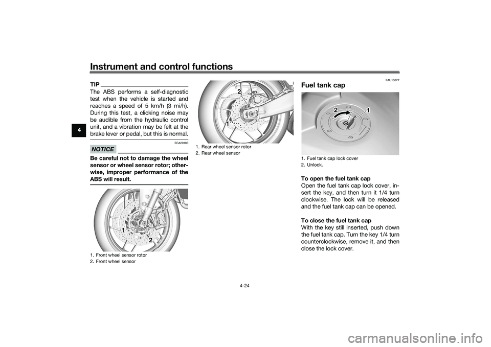
Fuel tank capTo open the fuel tank cap
Open the fuel tank cap lock cover, in-
sert the key, and then turn it 1/4 turn
clockwise. The lock will be released
and the fuel tank cap can be opened.
To close the fuel tank cap
With the key still inserted, push down
the fuel tank cap. Turn the key 1/4 turn
counterclockwise, remove it, and then
close the lock cover.
1. Front wheel sensor rotor
2. Front wheel sensor
111
22
1. Rear wheel sensor rotor
2. Rear wheel sensor
1 1 1 2 2
1. Fuel tank cap lock cover
2. Unlock.
1
2
UBAPE0E0.book Page 24 Thursday, December 24, 2020 9:14 AM
Page 47 of 116
Instrument and control functions
4-25
4
TIPThe fuel tank cap cannot be closed un-
less the key is in the lock. In addition,
the key cannot be removed if the cap is
not properly closed and locked.
WARNING
EWA11092
Make sure that the fuel tank cap is
properly closed after filling fuel.
Leakin g fuel is a fire hazar d.
EAU13222
FuelMake sure there is sufficient gasoline in
the tank.
WARNING
EWA10882
Gasoline an d gasoline vapors are
extremely flammab le. To avoid fires
an d explosions an d to re duce the
risk of injury when refueling , follow
these instructions.1. Before refueling, turn off the en- gine and be sure that no one is sit-
ting on the vehicle. Never refuel
while smoking, or while in the vi-
cinity of sparks, open flames, or
other sources of ignition such as
the pilot lights of water heaters
and clothes dryers.
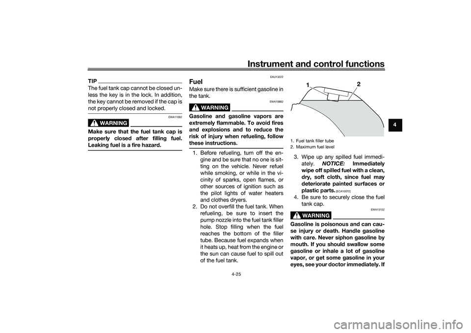
2. Do not overfill the fuel tank. When refueling, be sure to insert the
pump nozzle into the fuel tank filler
hole. Stop filling when the fuel
reaches the bottom of the filler
tube. Because fuel expands when
it heats up, heat from the engine or
the sun can cause fuel to spill out
of the fuel tank. 3. Wipe up any spilled fuel immedi-
ately. NOTICE: Immediately
wipe off spille d fuel with a clean,
d ry, soft cloth, since fuel may
d eteriorate painte d surfaces or
plastic parts.
[ECA10072]
4. Be sure to securely close the fuel tank cap.
WARNING
EWA15152
Gasoline is poisonous an d can cau-
se injury or death. Han dle gasoline
with care. Never siphon gasoline by
mouth. If you shoul d swallow some
g asoline or inhale a lot of g asoline
vapor, or g et some gasoline in your
eyes, see your d octor immediately. If1. Fuel tank filler tube
2. Maximum fuel level
1
2
UBAPE0E0.book Page 25 Thursday, December 24, 2020 9:14 AM
Page 50 of 116
Instrument and control functions
4-28
4
EAU92640
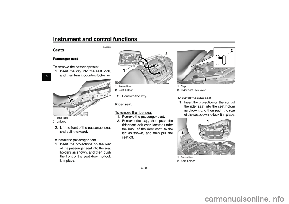
SeatsPassen ger seat
To remove the passenger seat1. Insert the key into the seat lock, and then turn it counterclockwise.
2. Lift the front of the passenger seat and pull it forward.
To install the passenger seat1. Insert the projections on the rear of the passenger seat into the seat
holders as shown, and then push
the front of the seat down to lock
it in place. 2. Remove the key.
Ri der seat
To remove the rider seat
1. Remove the passenger seat.
2. Remove the cap, then push the rider seat lock lever, located under
the back of the rider seat, to the
left as shown, and then pull the
seat off. To install the rider seat
1. Insert the projection on the front of
the rider seat into the seat holder
as shown, and then push the rear
of the seat down to lock it in place.
1. Seat lock
2. Unlock.
1 1 1
2
2
1. Projection
2. Seat holder
1
2
1. Cap
2. Rider seat lock lever
1. Projection
2. Seat holder
2
1 1 11 1 1
2 2
UBAPE0E0.book Page 28 Thursday, December 24, 2020 9:14 AM
Page 67 of 116
Operation and important ri din g points
6-5
6
EAU17214
Parkin gWhen parking, stop the engine, and
then remove the key from the main
switch.
WARNING
EWA10312
Since the en gine an d exhaust
system can b ecome very hot,
park in a place where pe destri-
ans or chil dren are not likely to
touch them an d b e burne d.
Do not park on a slope or on soft
groun d, otherwise the vehicle
may overturn, increasin g the
risk of a fuel leak an d fire.
Do not park near grass or other
flamma ble materials which
mi ght catch fire.
UBAPE0E0.book Page 5 Thursday, December 24, 2020 9:14 AM