service YAMAHA TRACER 900 GT 2021 Owners Manual
[x] Cancel search | Manufacturer: YAMAHA, Model Year: 2021, Model line: TRACER 900 GT, Model: YAMAHA TRACER 900 GT 2021Pages: 116, PDF Size: 4.35 MB
Page 43 of 116
Instrument and control functions
4-21
4
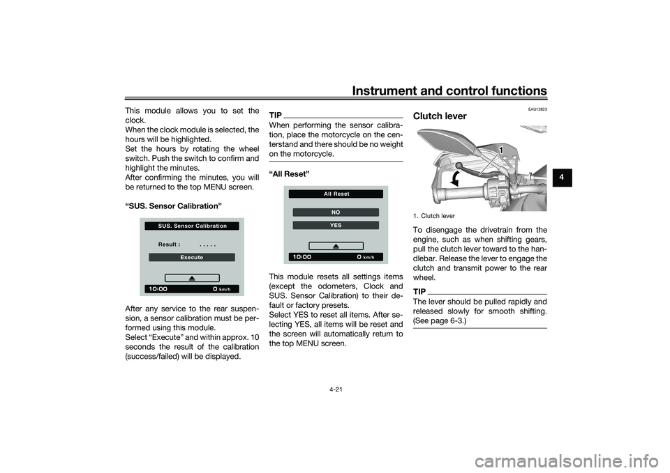
This module allows you to set the
clock.
When the clock module is selected, the
hours will be highlighted.
Set the hours by rotating the wheel
switch. Push the switch to confirm and
highlight the minutes.
After confirming the minutes, you will
be returned to the top MENU screen.
“SUS. Sensor Cali
bration”
After any service to the rear suspen-
sion, a sensor calibration must be per-
formed using this module.
Select “Execute” and within approx. 10
seconds the result of the calibration
(success/failed) will be displayed.
TIPWhen performing the sensor calibra-
tion, place the motorcycle on the cen-
terstand and there should be no weight
on the motorcycle.“All Reset”
This module resets all settings items
(except the odometers, Clock and
SUS. Sensor Calibration) to their de-
fault or factory presets.
Select YES to reset all items. After se-
lecting YES, all items will be reset and
the screen will automatically return to
the top MENU screen.
EAU12823
Clutch leverTo disengage the drivetrain from the
engine, such as when shifting gears,
pull the clutch lever toward to the han-
dlebar. Release the lever to engage the
clutch and transmit power to the rear
wheel.TIPThe lever should be pulled rapidly and
released slowly for smooth shifting.
(See page 6-3.)
Result : . . . . .
Execute
km/h
S U S. S ensor Calibration
NOYES
km/h
All Reset
1. Clutch lever
111
UBAPE0E0.book Page 21 Thursday, December 24, 2020 9:14 AM
Page 55 of 116
Instrument and control functions
4-33
4
EAU92782
A djustin g the front an d rear
suspensionThis model is equipped with an elec-
tronically controlled suspension damp-
ing system (KADS). See pages 3-4,
4-13 for more information on KADS
and SUS-MODE.TIPAfter any service to the rear suspen-
sion, a sensor calibration must be per-
formed via the settings MENU. See
page 4-21 for more information on
SUS. Sensor Calibration.Sprin g preloa d of the front fork
WARNING
EWA10181
Always a djust both fork le gs equally,
otherwise poor han dlin g an d loss of
sta bility may result.NOTICE
ECA27260
Use extra care to avoi d scratching
the anod ized finish when makin g
suspension a djustments.
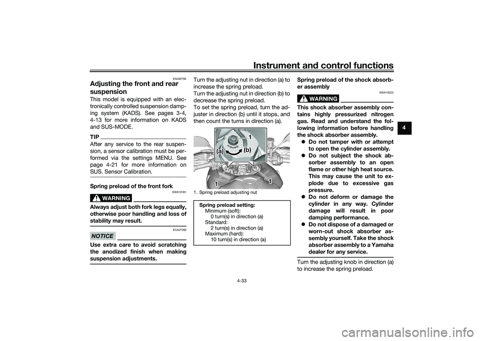
Turn the adjusting nut in direction (a) to
increase the spring preload.
Turn the adjusting nut in direction (b) to
decrease the spring preload.
To set the spring preload, turn the ad-
juster in direction (b) until it stops, and
then count the turns in direction (a). Sprin
g preloa d of the shock a bsor b-
er assem bly
WARNING
EWA10222
This shock a bsor ber assem bly con-
tains hig hly pressurize d nitro gen
g as. Rea d an d un derstan d the fol-
lowin g information before han dlin g
the shock a bsor ber assem bly.
Do not tamper with or attempt
to open the cylind er assembly.
Do not su bject the shock a b-
sor ber assem bly to an open
flame or other hi gh heat source.
This may cause the unit to ex-
plo de due to excessive gas
pressure.
Do not deform or damag e the
cylin der in any way. Cylin der
d ama ge will result in poor
d ampin g performance.
Do not dispose of a d amaged or
worn-out shock a bsor ber as-
sem bly yo
u
rself. Take the shock
a b sor ber assem bly to a Yamaha
d ealer for any service.
Turn the adjusting knob in direction (a)
to increase the spring preload.
1. Spring preload adjusting nut
Sprin g preloa d settin g:
Minimum (soft): 0 turn(s) in direction (a)
Standard: 2 turn(s) in direction (a)
Maximum (hard):
10 turn(s) in direction (a)
1 11
11
11(a) (a) (a)
(b) (b) (b)
UBAPE0E0.book Page 33 Thursday, December 24, 2020 9:14 AM
Page 68 of 116
Periodic maintenance an d a djustment
7-1
7
EAU17246
Periodic inspection, adjustment, and
lubrication will keep your vehicle in the
safest and most efficient condition
possible. Safety is an obligation of the
vehicle owner/operator. The most im-
portant points of vehicle inspection,
adjustment, and lubrication are ex-
plained on the following pages.
The intervals given in the periodic
maintenance charts should be simply
considered as a general guide under
normal riding conditions. However, de-
pending on the weather, terrain, geo-
graphical location, and individual use,
the maintenance intervals may need to
be shortened.
WARNING
EWA10322
Failure to properly maintain the vehi-
cle or performin g maintenance ac-
tivities incorrectly may increase
your risk of injury or death durin g
service or while usin g the vehicle. If
you are not familiar with vehicle ser-
vice, have a Yamaha d ealer perform
service.
WARNING
EWA15123
Turn off the en gine when performin g
maintenance unless otherwise
specified .
A runnin g en gine has movin g
parts that can catch on body
parts or clothin g an d electrical
parts that can cause shocks or
fires.
Runnin g the en gine while ser-
vicin g can lead to eye injury,
b urns, fire, or car bon monoxi de
poisonin g – possi bly lea din g to
d eath. See pag e 1-3 for more in-
formation a bout car bon monox-
i d e.
WARNING
EWA15461
Brake discs, calipers, drums, and
linin gs can b ecome very hot d uring
use. To avoi d possi ble burns, let
b rake components cool before
touchin g them.
EAU17303
Emission controls not only function to
ensure cleaner air, but are also vital to
proper engine operation and maximum
performance. In the following periodic
maintenance charts, the services relat-
ed to emissions control are grouped
separately. These services require
specialized data, knowledge, and
equipment. Maintenance, replace-
ment, or repair of the emission control
devices and systems may be per-
formed by any repair establishment or
individual that is certified (if applicable).
Yamaha dealers are trained and equipped to perform these particular
services.
UBAPE0E0.book Page 1 Thursday, December 24, 2020 9:14 AM
Page 75 of 116
Periodic maintenance an d a djustment
7-8
7
EAU72800
TIP Air filter
• This model’s air filter is equipped with a disposable oil-coated paper element, which must not be cleaned with com- pressed air to avoid damaging it.
• The air filter element needs to be replaced more frequently when riding in unusually wet or dusty areas.
Hydraulic brake service
• Regularly check and, if necessary, correct the brake fluid level.
• Every two years replace the internal components of the brake master cylinders and calipers, and change the brake fluid.
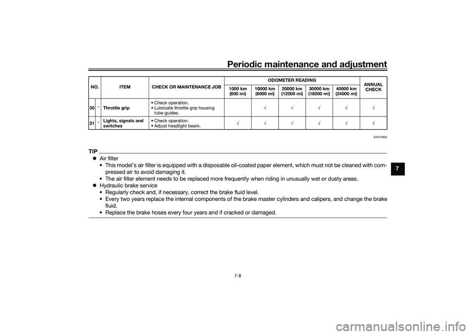
• Replace the brake hoses every four years and if cracked or damaged.30 *Throttle g rip • Check operation.
• Lubricate throttle grip housing
tube guides. √√√√√
31 *Li
ghts, si gnals an d
switches • Check operation.
• Adjust headlight beam.
√√√√√√
NO. ITEM CHECK OR MAINTENANCE JOB
ODOMETER READING
ANNUAL
CHECK
1000 km
(600 mi) 10000 km
(6000 mi) 20000 km
(12000 mi) 30000 km
(18000 mi) 40000 km
(24000 mi)
UBAPE0E0.book Page 8 Thursday, December 24, 2020 9:14 AM
Page 82 of 116
Periodic maintenance an d a djustment
7-15
7
EAU21403
Valve clearanceThe valves are an important engine
component, and since valve clearance
changes with use, they must be
checked and adjusted at the intervals
specified in the periodic maintenance
chart. Unadjusted valves can result in
improper air-fuel mixture, engine
noise, and eventually engine damage.
To prevent this from occurring, have
your Yamaha dealer check and adjust
the valve clearance at regular intervals.TIPThis service must be performed when
the engine is cold.
EAU64412
TiresTires are the only contact between the
vehicle and the road. Safety in all con-
ditions of riding depends on a relatively
small area of road contact. Therefore, it
is essential to maintain the tires in good
condition at all times and replace them
at the appropriate time with the speci-
fied tires.
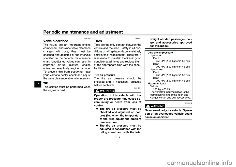
Tire air pressure
The tire air pressure should be
checked and, if necessary, adjusted
before each ride.
WARNING
EWA10504
Operation of this vehicle with im-
proper tire pressure may cause se-
vere injury or death from loss of
control. The tire air pressure must be
checked and a djuste d on col d
tires (i.e., when the temperature
of the tires equals the amb ient
temperature).
The tire air pressure must be
a d juste d in accor dance with the
ri din g speed and with the total wei
ght of ri der, passen ger, car-
g o, an d accessories approve d
for this mo del.
WARNING
EWA10512
Never overloa d your vehicle. Opera-
tion of an overload ed vehicle coul d
cause an acci dent.Col d tire air pressure:
1 person: Front:250 kPa (2.50 kgf/cm², 36 psi)
Rear: 290 kPa (2.90 kgf/cm², 42 psi)
2 persons:
Front:250 kPa (2.50 kgf/cm², 36 psi)
Rear:
290 kPa (2.90 kgf/cm², 42 psi)
Maximum load :
Vehicle:
193 kg (425 lb)
The vehicle’s maximum load is the
combined weight of the rider, pas-
senger, cargo, and any accessories.
UBAPE0E0.book Page 15 Thursday, December 24, 2020 9:14 AM
Page 86 of 116
Periodic maintenance an d a djustment
7-19
7 b
rakin g performance, which may re-
sult in loss of control and an acci-
d ent.
EAU36505
Brake li ght switchesThe brake light should come on just
before braking takes effect. The brake
light is activated by switches connect-
ed to the brake lever and brake pedal.
Since the brake light switches are
components of the anti-lock brake sys-
tem, they should only be serviced by a
Yamaha dealer.
EAU22393
Checkin g the front an d rear
b rake pa dsThe front and rear brake pads must be
checked for wear at the intervals spec-
ified in the periodic maintenance and
lubrication chart.
EAU36891
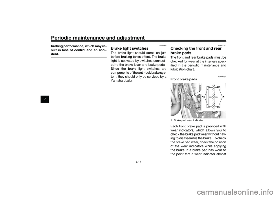
Front brake pa ds
Each front brake pad is provided with
wear indicators, which allows you to
check the brake pad wear without hav-
ing to disassemble the brake. To check
the brake pad wear, check the position
of the wear indicators while applying
the brake. If a brake pad has worn to
the point that a wear indicator almost1. Brake pad wear indicator
1
1
UBAPE0E0.book Page 19 Thursday, December 24, 2020 9:14 AM
Page 90 of 116
Periodic maintenance an d a djustment
7-23
7 3. Place the motorcycle on the cen-
terstand.
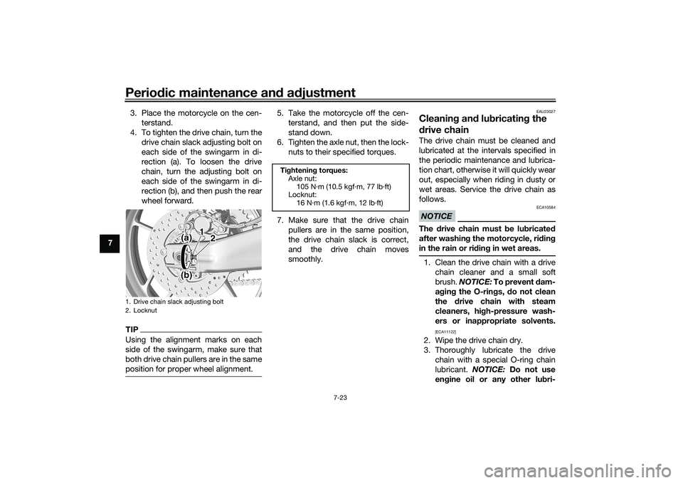
4. To tighten the drive chain, turn the drive chain slack adjusting bolt on
each side of the swingarm in di-
rection (a). To loosen the drive
chain, turn the adjusting bolt on
each side of the swingarm in di-
rection (b), and then push the rear
wheel forward.
TIPUsing the alignment marks on each
side of the swingarm, make sure that
both drive chain pullers are in the same
position for proper wheel alignment.
5. Take the motorcycle off the cen-terstand, and then put the side-
stand down.
6. Tighten the axle nut, then the lock- nuts to their specified torques.
7. Make sure that the drive chain pullers are in the same position,
the drive chain slack is correct,
and the drive chain moves
smoothly.
EAU23027
Cleanin g an d lu bricatin g the
d rive chainThe drive chain must be cleaned and
lubricated at the intervals specified in
the periodic maintenance and lubrica-
tion chart, otherwise it will quickly wear
out, especially when riding in dusty or
wet areas. Service the drive chain as
follows.NOTICE
ECA10584
The drive chain must be lu bricated
after washin g the motorcycle, ri din g
in the rain or ri din g in wet areas.1. Clean the drive chain with a drive
chain cleaner and a small soft
brush. NOTICE: To prevent d am-
a g in g the O-rin gs, do not clean
the drive chain with steam
cleaners, hi gh-pressure wash-
ers or inappropriate solvents.
[ECA11122]
2. Wipe the drive chain dry.
3. Thoroughly lubricate the drive chain with a special O-ring chain
lubricant. NOTICE: Do not use
en gine oil or any other lu bri-
1. Drive chain slack adjusting bolt
2. Locknut
(a) 1
2
(b)
Ti ghtenin g torques:
Axle nut: 105 N·m (10.5 kgf·m, 77 lb·ft)
Locknut:
16 N·m (1.6 kgf·m, 12 lb·ft)
UBAPE0E0.book Page 23 Thursday, December 24, 2020 9:14 AM
Page 100 of 116
Periodic maintenance an d a djustment
7-33
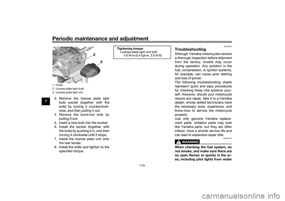
7 3. Remove the license plate light
bulb socket (together with the
bulb) by turning it counterclock-
wise, and then pulling it out.
4. Remove the burnt-out bulb by pulling it out.
5. Insert a new bulb into the socket.
6. Install the socket (together with the bulb) by pushing it in, and then
turning it clockwise until it stops.
7. Install the license plate unit onto the rear fender.
8. Install the bolts and tighten to the specified torque.
EAU25872
Trou bleshootin gAlthough Yamaha motorcycles receive
a thorough inspection before shipment
from the factory, trouble may occur
during operation. Any problem in the
fuel, compression, or ignition systems,
for example, can cause poor starting
and loss of power.
The following troubleshooting charts
represent quick and easy procedures
for checking these vital systems your-
self. However, should your motorcycle
require any repair, take it to a Yamaha
dealer, whose skilled technicians have
the necessary tools, experience, and
know-how to service the motorcycle
properly.
Use only genuine Yamaha replace-
ment parts. Imitation parts may look
like Yamaha parts, but they are often
inferior, have a shorter service life and
can lead to expensive repair bills.
WARNING
EWA15142
When checkin g the fuel system, do
not smoke, an d make sure there are
no open flames or sparks in the ar-
ea, inclu din g pilot li ghts from water
1. Collar
2. License plate light bulb
3. License plate light unit
3
2
1 1 1
Ti
ghtenin g torque:
License plate light unit bolt:
4.0 N·m (0.4 kgf·m, 3.0 lb·ft)
UBAPE0E0.book Page 33 Thursday, December 24, 2020 9:14 AM
Page 108 of 116
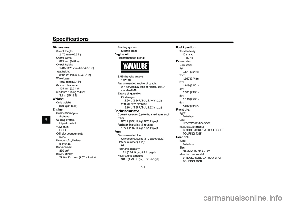
Specifications
9-1
9
Dimensions:Overall length:2175 mm (85.6 in)
Overall width:
885 mm (34.8 in)
Overall height: 1430/1470 mm (56.3/57.9 in)
Seat height: 810/825 mm (31.9/32.5 in)
Wheelbase:
1500 mm (59.1 in)
Ground clearance: 135 mm (5.31 in)
Minimum turning radius: 3.1 m (10.17 ft)Wei ght:Curb weight:
220 kg (485 lb)Engine:Combustion cycle:
4-stroke
Cooling system: Liquid cooled
Valve train: DOHC
Cylinder arrangement:
Inline
Number of cylinders: 3-cylinder
Displacement: 890 cm³
Bore × stroke:
78.0 × 62.1 mm (3.07 × 2.44 in) Starting system:
Electric starter
Engine oil:Recommended brand:
SAE viscosity grades:
10W-40
Recommended engine oil grade:
API service SG type or higher, JASO
standard MA
Engine oil quantity:
Oil change: 2.80 L (2.96 US qt, 2.46 Imp.qt)
With oil filter removal:
3.20 L (3.38 US qt, 2.82 Imp.qt)Coolant quantity:Coolant reservoir (up to the maximum level
mark):0.28 L (0.30 US qt, 0.25 Imp.qt)
Radiator (including all routes): 1.72 L (1.82 US qt, 1.51 Imp.qt)Fuel:Recommended fuel:Unleaded gasoline (E10 acceptable)
Octane number (RON): 95
Fuel tank capacity:
19 L (5.0 US gal, 4.2 Imp.gal)
Fuel reserve amount: 3.0 L (0.79 US gal, 0.66 Imp.gal)
Fuel injection:Throttle body:ID mark: B7N1Drivetrain:Gear ratio:
1st:2.571 (36/14)
2nd:
1.947 (37/19)
3rd: 1.619 (34/21)
4th: 1.381 (29/21)
5th:
1.190 (25/21)
6th: 1.037 (28/27)Front tire:Type:
Tubeless
Size: 120/70ZR17M/C (58W)
Manufacturer/model: BRIDGESTONE/BATTLAX SPORT
TOURING T32FRear tire:Type:
Tubeless
Size: 180/55ZR17M/C (73W)
Manufacturer/model: BRIDGESTONE/BATTLAX SPORT
TOURING T32R
UBAPE0E0.book Page 1 Thursday, December 24, 2020 9:14 AM
Page 111 of 116
Consumer information
10-2
10
The model label is affixed to the frame
under the rider seat. (See page 4-28.)
Record the information on this label in
the space provided. This information
will be needed when ordering spare
parts from a Yamaha dealer.
EAU69910
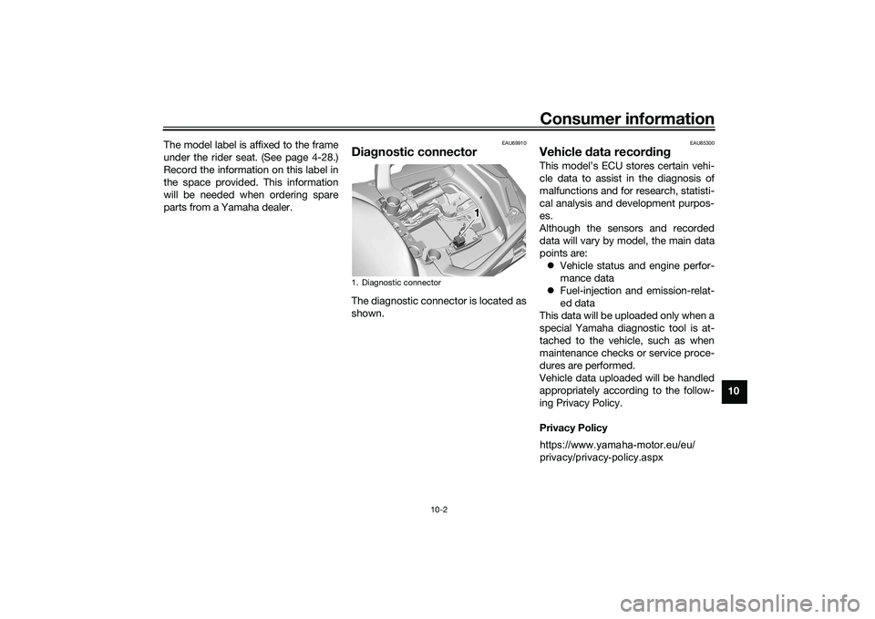
Dia
gnostic connectorThe diagnostic connector is located as
shown.
EAU85300
Vehicle data recor din gThis model’s ECU stores certain vehi-
cle data to assist in the diagnosis of
malfunctions and for research, statisti-
cal analysis and development purpos-
es.
Although the sensors and recorded
data will vary by model, the main data
points are:
Vehicle status and engine perfor-
mance data
Fuel-injection and emission-relat-
ed data
This data will be uploaded only when a
special Yamaha diagnostic tool is at-
tached to the vehicle, such as when
maintenance checks or service proce-
dures are performed.
Vehicle data uploaded will be handled
appropriately according to the follow-
ing Privacy Policy.
Privacy Policy
1. Diagnostic connector
111
https://www.yamaha-motor.eu/eu/
privacy/privacy-policy.aspx
UBAPE0E0.book Page 2 Thursday, December 24, 2020 9:14 AM