set clock YAMAHA TRACER 900 GT 2021 Owners Manual
[x] Cancel search | Manufacturer: YAMAHA, Model Year: 2021, Model line: TRACER 900 GT, Model: YAMAHA TRACER 900 GT 2021Pages: 116, PDF Size: 4.35 MB
Page 26 of 116
Instrument and control functions
4-4
4
EAU66040
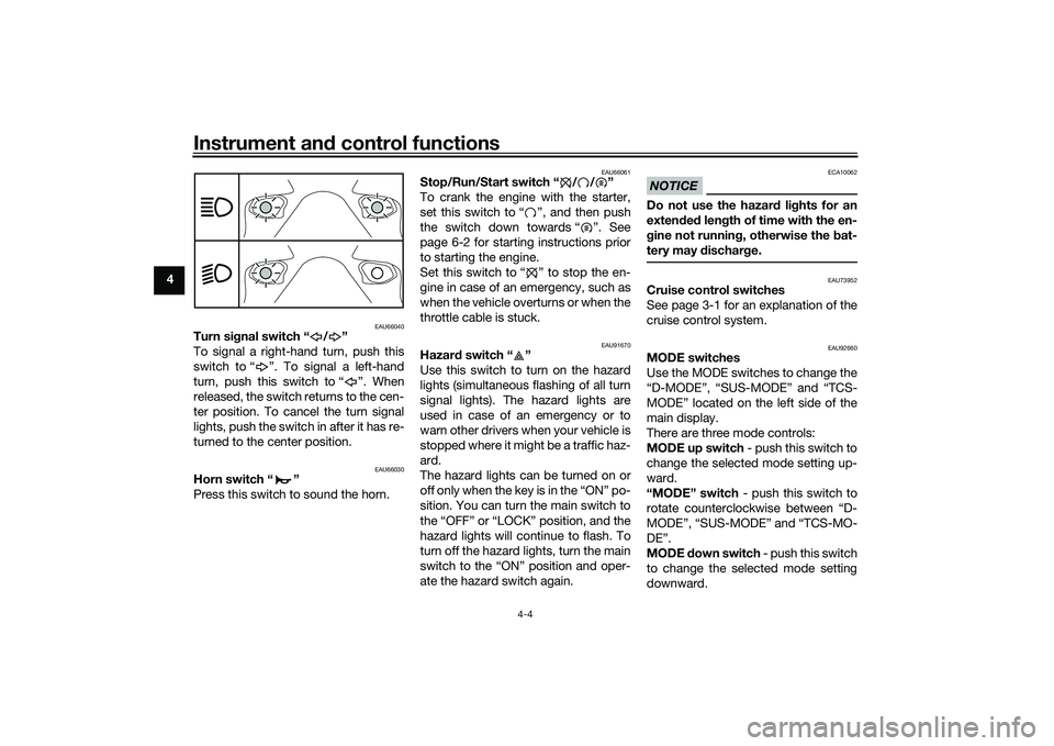
Turn si gnal switch “ / ”
To signal a right-hand turn, push this
switch to “ ”. To signal a left-hand
turn, push this switch to “ ”. When
released, the switch returns to the cen-
ter position. To cancel the turn signal
lights, push the switch in after it has re-
turned to the center position.
EAU66030
Horn switch “ ”
Press this switch to sound the horn.
EAU66061
Stop/Run/Start switch “ / / ”
To crank the engine with the starter,
set this switch to “ ”, and then push
the switch down towards “ ”. See
page 6-2 for starting instructions prior
to starting the engine.
Set this switch to “ ” to stop the en-
gine in case of an emergency, such as
when the vehicle overturns or when the
throttle cable is stuck.
EAU91670
Hazar d switch “ ”
Use this switch to turn on the hazard
lights (simultaneous flashing of all turn
signal lights). The hazard lights are
used in case of an emergency or to
warn other drivers when your vehicle is
stopped where it might be a traffic haz-
ard.
The hazard lights can be turned on or
o f f o n ly w he n the k e y is i n t he “ ON ” p o -
sition. You can turn the main switch to
the “OFF” or “LOCK” position, and the
hazard lights will continue to flash. To
turn off the hazard lights, turn the main
switch to the “ON” position and oper-
ate the hazard switch again.
NOTICE
ECA10062
Do not use the hazard lights for an
exten ded len gth of time with the en-
g ine not runnin g, otherwise the bat-
tery may dischar ge.
EAU73952
Cruise control switches
See page 3-1 for an explanation of the
cruise control system.
EAU92660
MODE switches
Use the MODE switches to change the
“D-MODE”, “SUS-MODE” and “TCS-
MODE” located on the left side of the
main display.
There are three mode controls:
MODE up switch - push this switch to
change the selected mode setting up-
ward.
“MODE” switch - push this switch to
rotate counterclockwise between “D-
MODE”, “SUS-MODE” and “TCS-MO-
DE”.
MODE down switch - push this switch
to change the selected mode setting
downward.
UBAPE0E0.book Page 4 Thursday, December 24, 2020 9:14 AM
Page 31 of 116
Instrument and control functions
4-9
4
If a malfunction is detected, this
light will come on and the oil pres-
sure icon will flash.
NOTICE
ECA22441
If the oil pressure an d coolant warn-
in g li ght does not go off after start-
in g the en gine or if it comes on while
the en gine is runnin g, stop the vehi-
cle an d en gine imme diately.
If the en gine is overheatin g, the
coolant temperature warnin g
icon will come on. Let the en-
g ine cool. Check the coolant
level (see pa ge 7-36).
If the en gine oil pressure is low,
the oil pressure warnin g icon
will come on. Check the oil level
(see pa ge 7-10).
If the warnin g lig ht remains on
after lettin g the en gine cool an d
confirmin g the proper oil level,
have a Yamaha dealer check
the vehicle. Do not continue to
operate the vehicle!
EAU92731
Auxiliary system warnin g lig ht “ ”
This warning light comes on if a prob-
lem is detected in a non-engine-related
system.TIPWhen the vehicle is turned on, this light
should come on for a few seconds and
then go off. Otherwise, have a Yamaha
dealer check the vehicle.
EAU92575
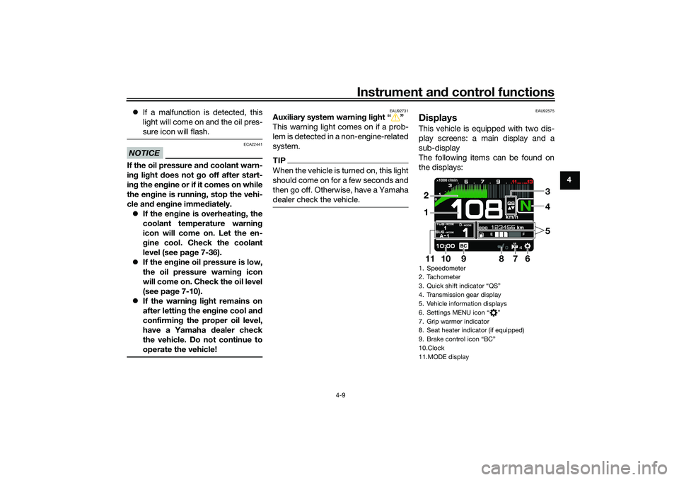
DisplaysThis vehicle is equipped with two dis-
play screens: a main display and a
sub-display
The following items can be found on
the displays:1. Speedometer
2. Tachometer
3. Quick shift indicator “QS”
4. Transmission gear display
5. Vehicle information displays
6. Settings MENU icon “ ”
7. Grip warmer indicator
8. Seat heater indicator (if equipped)
9. Brake control icon “BC”
10.Clock
11.MODE display
4
7
6
1011
12
9
35
8
UBAPE0E0.book Page 9 Thursday, December 24, 2020 9:14 AM
Page 32 of 116
Instrument and control functions
4-10
4
TIP This model uses thin-film-transis-
tor liquid-crystal displays (TFT
LCD) for good contrast and read-
ability in various lighting condi-
tions. However, due to the nature
of this technology, it is normal for
a small number of pixels to be in-
active.
The display units can be switched
between kilometers/miles and cel-
sius/farenheit. See “Unit” on page
4-20.
WARNING
EWA18210
Stop the vehicle before makin g any
settin g chan ges. Chan gin g settin gs
while rid ing can d istract the opera-
tor an d increase the risk of an acci-
d ent.Speed ometer
The speedometer shows the vehicle’s
traveling speed. Tachometer
The tachometer shows the engine
speed, as measured by the rotational
velocity of the crankshaft, in revolu-
tions per minute (r/min).
NOTICE
ECA10032
Do not operate the en
gine in the ta-
chometer red zone.
Re d zone: 10600 r/min an d a boveVehicle information d isplays
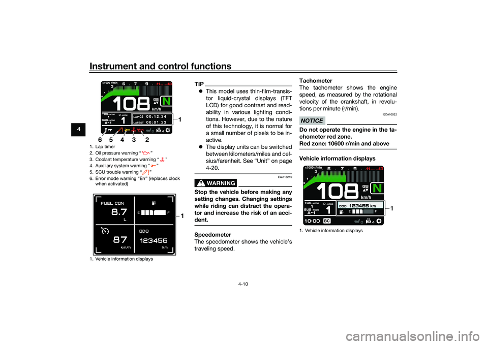
1. Lap timer
2. Oil pressure warning “ ”
3. Coolant temperature warning “ ”
4. Auxiliary system warning “ ”
5. SCU trouble warning “ ”
6. Error mode warning “Err” (replaces clock
when activated)
1. Vehicle information displays
LAP
02
LATEST
00:12.3 4
00:01.23
1
4 3
2
6
5
1
1. Vehicle information displays
1
UBAPE0E0.book Page 10 Thursday, December 24, 2020 9:14 AM
Page 35 of 116
Instrument and control functions
4-13
4
Displays how much fuel has been con-
sumed since the trip meter was last re-
set.
TIPThe instantaneous fuel consumption
function should be used for general
reference only. Do not use this figure to
estimate the distance that can be trav-
eled on the current tank of fuel.Trip time:Displays engine running time.
Cruise control speed setting:Displays the selected speed setting for
the cruise control system. To adjust
this speed setting, see page 3-1 for an
explanation of the cruise control sys-
tem. To reset information display items (if
able):1. Rotate the wheel switch to high-
light one of the six vehicle informa-
tion displays.
2. Press the wheel switch inward to select the information display.
3. Rotate the wheel switch to select the desired information display
item.
4. Press and hold the wheel switch inward until the display item is re-
set.
Transmission gear display
This shows which gear the transmis-
sion is in. This model has 6 gears and a
neutral position. The neutral position is
indicated by the neutral indicator
light “ ” and by the transmission gear
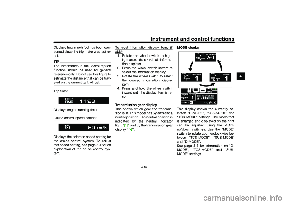
display “ ”. MODE
display
This display shows the currently se-
lected “D-MODE”, “SUS-MODE” and
“TCS-MODE” settings. The mode that
is enlarged and displayed on the right
can be adjusted using the MODE
up/down switches. Use the “MODE”
switch to rotate counterclockwise be-
tween “TCS-MODE”, “SUS-MODE”
and “D-MODE”.
See page 3-3 for information on “D-
MODE”, “TCS-MODE” and “SUS-
MODE” settings.
UBAPE0E0.book Page 13 Thursday, December 24, 2020 9:14 AM
Page 36 of 116
Instrument and control functions
4-14
4
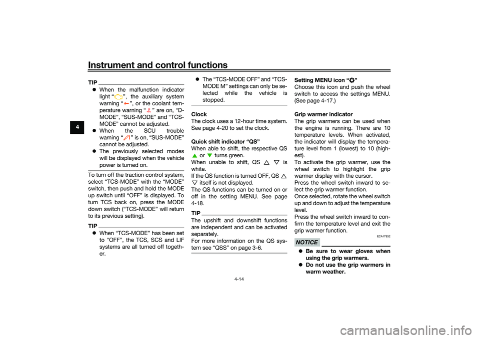
TIP When the malfunction indicator
light “ ”, the auxiliary system
warning “ ”, or the coolant tem-
perature warning “ ” are on, “D-
MODE”, “SUS-MODE” and “TCS-
MODE” cannot be adjusted.
When the SCU trouble
warning “ ” is on, “SUS-MODE”
cannot be adjusted.
The previously selected modes
will be displayed when the vehicle
power is turned on.To turn off the traction control system,
select “TCS-MODE” with the “MODE”
switch, then push and hold the MODE
up switch until “OFF” is displayed. To
turn TCS back on, press the MODE
down switch (“TCS-MODE” will return
to its previous setting).TIPWhen “TCS-MODE” has been set
to “OFF”, the TCS, SCS and LIF
systems are all turned off togeth-
er.
The “TCS-MODE OFF” and “TCS-
MODE M” settings can only be se-
lected while the vehicle is
stopped.
Clock
The clock uses a 12-hour time system.
See page 4-20 to set the clock.
Quick shift in dicator “QS”
When able to shift, the respective QS or turns green.
When unable to shift, QS is
white.
If the QS function is turned OFF, QS itself is not displayed.
The QS functions can be turned on or
off in the setting MENU. See page
4-18.TIPThe upshift and downshift functions
are independent and can be activated
separately.
For more information on the QS sys-
Settin g MENU icon “ ”
Choose this icon and push the wheel
switch to access the settings MENU.
(See page 4-17.)
Grip warmer in dicator
The grip warmers can be used when
the engine is running. There are 10
temperature levels. When activated,
the indicator will display the tempera-
ture level from 1 (lowest) to 10 (high-
est).
To activate the grip warmer, use the
wheel switch to highlight the grip
warmer display with the cursor.
Press the wheel switch inward to se-
lect the grip warmer function.
Once selected, rotate the wheel switch
up and down to adjust the temperature
level.
Press the wheel switch inward to con-
firm the temperature level and exit the
grip warmer function.NOTICE
ECA17932
Be sure to wear gloves when
usin g the g rip warmers.
Do not use the grip warmers in
warm weather.
UBAPE0E0.book Page 14 Thursday, December 24, 2020 9:14 AM
Page 39 of 116
Instrument and control functions
4-17
4
EAU92793
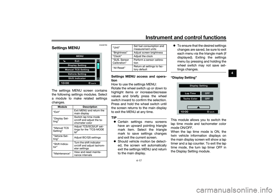
Settin gs MENUThe settings MENU screen contains
the following settings modules. Select
a module to make related settings
changes. Settin
gs MENU access an d opera-
tion
How to use the settings MENU:
Rotate the wheel switch up or down to
highlight items or increase/decrease
values and briefly press the wheel
switch inward to confirm the selection.
Press and hold the wheel switch until
the screen returns to the main display
to exit the MENU at any time.
TIP Certain settings menu screens
have an upward pointing triangle
mark item. Select the triangle
mark to save settings changes
and exit the current screen.
Should vehicle motion be detect-
ed, the screen will automatically
exit the settings MENU and return
to the main display.
To ensure that the desired settings
changes are saved, be sure to exit
each menu via the triangle mark (if
displayed). Exiting the settings
menu by pressing and holding the
wheel switch may not save set-
tings changes.
“Display Settin g”
This module allows you to switch the
lap time mode and tachometer color
mode ON/OFF.
When the lap time mode is ON, the
twin vehicle information displays on
the main display screen will show a lap
timer and a lap counter. To exit the lap
time mode, the turn lap timer OFF in
the Display Setting module.
Mo dule Description
“Exit” Exit MENU and return the
main display
“Display Set-
ting” Switch lap time mode
on/off and adjust the ta-
chometer color
“Manual TCS
Setting” Adjust TCS/SCS/LIF set-
tings for the “TCS-MODE
M”
“Vehicle Set-
ting” Adjust BC/QS settings
“Shift Indica-
tor” Turn the shift indicator
on/off and adjust tachom-
eter settings
“Maintenance” View and reset mainte-
nance intervals
Display S
etting
Exit
Manual TCS S ettingVehicle S ettingShift Indicator
km/h
MENU
Set fuel consumption and
measurement units
Adjust screen brightness
Adjust the clock
CalibrationŽ Perform a sensor calibra-
tion
Return all settings to fac-
tory default
Lap Time OFFTacho Color OFF
km/h
Display Setting
UBAPE0E0.book Page 17 Thursday, December 24, 2020 9:14 AM
Page 42 of 116
Instrument and control functions
4-20
4 r/min value by increments of 200 r/min.
“IND Stop” is settable between 6200 -
13000 r/min.
“Maintenance”
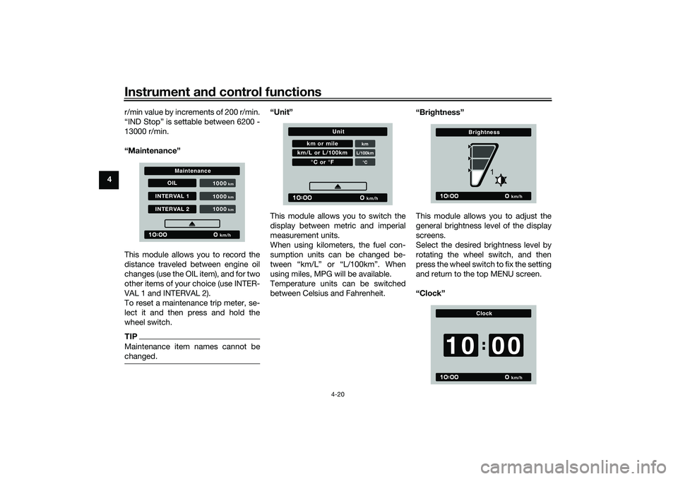
This module allows you to record the
distance traveled between engine oil
changes (use the OIL item), and for two
other items of your choice (use INTER-
VAL 1 and INTERVAL 2).
To reset a maintenance trip meter, se-
lect it and then press and hold the
wheel switch.
TIPMaintenance item names cannot be
changed.
“Unit”
This module allows you to switch the
display between metric and imperial
measurement units.
When using kilometers, the fuel con-
sumption units can be changed be-
tween “km/L” or “L/100km”. When
using miles, MPG will be available.
Temperature units can be switched
between Celsius and Fahrenheit. “Brig
htness”
This module allows you to adjust the
general brightness level of the display
screens.
Select the desired brightness level by
rotating the wheel switch, and then
press the wheel switch to fix the setting
and return to the top MENU screen.
“Clock”
OIL
INTERVAL 1INTERVAL 2 1000
km/h
km
1000
km
1000
km
Maintenance
km or mile
kmL/100km°C
km/L or L/100km
°C or °F
km/h
Unit
km/h
Brightness
1
km/h
Clock
0010
UBAPE0E0.book Page 20 Thursday, December 24, 2020 9:14 AM
Page 43 of 116
Instrument and control functions
4-21
4
This module allows you to set the
clock.
When the clock module is selected, the
hours will be highlighted.
Set the hours by rotating the wheel
switch. Push the switch to confirm and
highlight the minutes.
After confirming the minutes, you will
be returned to the top MENU screen.
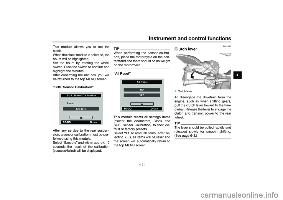
“SUS. Sensor Cali
bration”
After any service to the rear suspen-
sion, a sensor calibration must be per-
formed using this module.
Select “Execute” and within approx. 10
seconds the result of the calibration
(success/failed) will be displayed.
TIPWhen performing the sensor calibra-
tion, place the motorcycle on the cen-
terstand and there should be no weight
on the motorcycle.“All Reset”
This module resets all settings items
(except the odometers, Clock and
SUS. Sensor Calibration) to their de-
fault or factory presets.
Select YES to reset all items. After se-
lecting YES, all items will be reset and
the screen will automatically return to
the top MENU screen.
EAU12823
Clutch leverTo disengage the drivetrain from the
engine, such as when shifting gears,
pull the clutch lever toward to the han-
dlebar. Release the lever to engage the
clutch and transmit power to the rear
wheel.TIPThe lever should be pulled rapidly and
released slowly for smooth shifting.
(See page 6-3.)
Result : . . . . .
Execute
km/h
S U S. S ensor Calibration
NOYES
km/h
All Reset
1. Clutch lever
111
UBAPE0E0.book Page 21 Thursday, December 24, 2020 9:14 AM