YAMAHA TT600RE 2004 Service Manual
TT600RE 2004
YAMAHA
YAMAHA
https://www.carmanualsonline.info/img/51/57493/w960_57493-0.png
YAMAHA TT600RE 2004 Service Manual
Trending: seat adjustment, ABS, air bleeding, checking oil, tow, brake light, high beam
Page 211 of 382
ENGENGINE DISASSEMBLY
5-7
7. Remove:
•Gasket (1) (cylinder head)
•Pins (2)
•Cylinder (3)
•Gasket (4) (cylinder)
8. Remove:
•Pins (1)
9. Remove:
•Pin ring (1)
NOTE:
Before removing the pin ring, cover the crankcase
with a clean cloth to prevent the ring falling into
the crankcase cavity.
10. Remove:
•Pin (1)
•Piston (2)
NOTE:
Before removing the pin, burr the pin housing
groove. If it is hard to pull out the pin even with the
groove burred, use the pin puller.
ProCarManuals.com
Page 212 of 382
ENGINE DISASSEMBLY
5-8
ENG
Avoid using the hammer to pull the pin out.
CAUTION: Piston pin puller set:
P/N. 90890-01304
3. Remove:
•Neutral gear switch cable (1)
2. Remove:
•Intermediate starter gear (1)
•Bearing (2)
•Distributor shaft (3)
INTERMEDIATE STARTER GEAR, CRANKCASE
COVER (L) AND GENERATOR STATOR
NOTE:
With the engine installed, maintenance of the inter-
mediate starter gear and the crankcase cover (L)
may be performed by removing the following parts.
•Exhaust pipe
•Starter
•Sprocket cover
1. Remove:
•Cover (1) intermediate starter gear
•Centring pins
•Gasket
ProCarManuals.com
Page 213 of 382
ENGENGINE DISASSEMBLY
5-9
4. Remove:
•Crankcase cover gasket (1) (L)
•Centring pins
•Seal ring and O-ring
•Gasket
6. Remove:
•Cable clamp (1)
•Coil (2)
•Stator (3)
CRANKCASE COVER (R), CLUTCH, PRIMARY
DRIVE GEAR AND BALANCER SHAFT GEAR
NOTE:
The clutch, the primary gear and the balance gear
may be inspected with the engine installed by
removing the following parts.
•Footrest (R)
•Oil delivery hose screw
5. Remove:
•Intermediate starter gear (1)
•Bearing (2)
•Distributor shaft (3)
ProCarManuals.com
Page 214 of 382
ENGINE DISASSEMBLY
5-10
ENG
2. Remove:
•Compression spring (1)
•Pressure plate (2)
•Ball (3)
•Friction plate (4)
•Clutch plate (5)
•Clutch boss spring (6)
•Clutch boss (7)
•Thrust plate (8)
•Clutch shroud (9)
•Push rod (10)
1. Remove:
•Engine oil delivery hose screw
•Copper washer
•Oil filter cover (1)
•Oil filter
•Seal ring and O-Ring
•Crankcase cover (2) (R)
NOTE:
•Before loosening the nut (11) (clutch shroud),
straighten the washer lock tab.
•To loosen the nut (clutch boss), block the
clutch boss using the special tool (12).
Clutch holding tool: P/N. 90890-04086
ProCarManuals.com
Page 215 of 382
ENGENGINE DISASSEMBLY
5-11
3. Remove
•Primary drive gear (1)
•Disc (2)
•Balancer drive gear (3)
•Disc (4)
•Key (5)
•Disc washer (6)
•Disc (7)
•Balancer gear (8)
•Straight key (9)
NOTE:
Before loosening the nut (9) (primary drive gear)
and nut (10) (balancer gear), straighten the wash
lock tab.
NOTE:
To loosen nuts (9) and (10), hold the rotor (CA
magneto) firmly in place using special tool (11).
Sheave holder: P/N. 90890-01701
Be careful not to touch jutting edges (12) on
the rotor with the sheave holder.
CAUTION:
4. Remove:
•Push lever (1)
•Spring
•Flat washer
NOTE:
Loosen the screw to remove the push rod.
ProCarManuals.com
Page 216 of 382
ENGINE DISASSEMBLY
5-12
ENG
OIL PUMP AND SHIFT LEVER
NOTE:
The oil pump and shift lever may be checked with
the engine installed by removing the following
parts:
•Footrest (R)
•Oil delivery hose screw
•Crankcase (R)
•Clutch
1. Remove:
•Circlip (1)
•Oil pump gear (2)
•Oil pump (3)
•O-rings (4)
2. Remove:
•Circlip (1) (from drive shaft)
•Ring (2)
•Circlip (3)
3. Remove:
•Circlip (1)
•Shift lever (2)
•Spring (3)
•Flat washer (4)
4. Remove:
•Stopper lever (1)
•Ring (2)
•Spring (3)
ProCarManuals.com
Page 217 of 382
ENGENGINE DISASSEMBLY
5-13
AC GENERATOR AND TIMING CHAIN
NOTE:
The AC generator may be inspected with the
engine installed by removing the following parts:
•Crankcase (L)
1. Remove:
•Nut (1)
•Washer (2)
•Rotor (3) (with starter gear)
•Bearing (4)
•Shim adjustment washer (5)
•Key (6)
NOTE:
To loosen the nut (rotor), lock the rotor with the
special tool (7).
Sheave holder: P/N. 90890-01701
Flywheel puller:P/N. 90890-01362
Be careful not to touch the jutting edges (8) on
the rotor with the special tool.
CAUTION:
NOTE:
Remove the rotor with the puller (1).
2. Remove:
•Chain guide (1)
•Timing chain (2)
ProCarManuals.com
Page 218 of 382
ENGINE DISASSEMBLY
5-14
ENG
CRANKCASE (R)
1. Remove:
•Crankcase (R)
NOTE:
•Loosen nuts starting from the one with the
highest number.
•Loosen all by 1/4 turn and then remove.
Removal procedure:
•Set the crankcase separating tool (1) in place.
▼▼▼▼▼▼▼▼▼▼▼▼▼▼▼▼▼▼▼▼▼▼▼▼▼▼▼▼▼
Crankcase separating tool: P/N. 90890-01135
NOTE:
When tightening the support bolts of the separat-
ing tool, be sure to keep the tool body parallel to
the engine crankcase. If necessary, a screw may
be slightly loosened to put the tool body on level.
•Applying pressure, strike the front engine
assembly flange, the drive shafts and the gear
cam plate with a rubber hammer. Then
remove the crankcase.
NOTE:
•If the crankcase fails come out, lever at points
(2), being careful not to damage the
crankcase.
•Turn the gear cam plate as shown in the fig-
ure to prevent it interfering with the crankcase.
ProCarManuals.com
Page 219 of 382
ENGENGINE DISASSEMBLY
5-15
•Be careful not to damage surfaces in con-
tact with the crankcase.
•Use a soft hammer to hit the engine
crankcase. Only hit the reinforced parts.
Do not hit the surface in contact with the
gasket. Work slowly and carefully. Be care-
ful to perform the separation uniformly. If
one end locks, remove pressure from the
thrust screw, realign and recommence. If it
is impossible to separate the crankcase,
check that all screws and components
have been disassembled. Do not use force.
CAUTION:
ProCarManuals.com
Page 220 of 382
ENGINE DISASSEMBLY
5-16
ENG
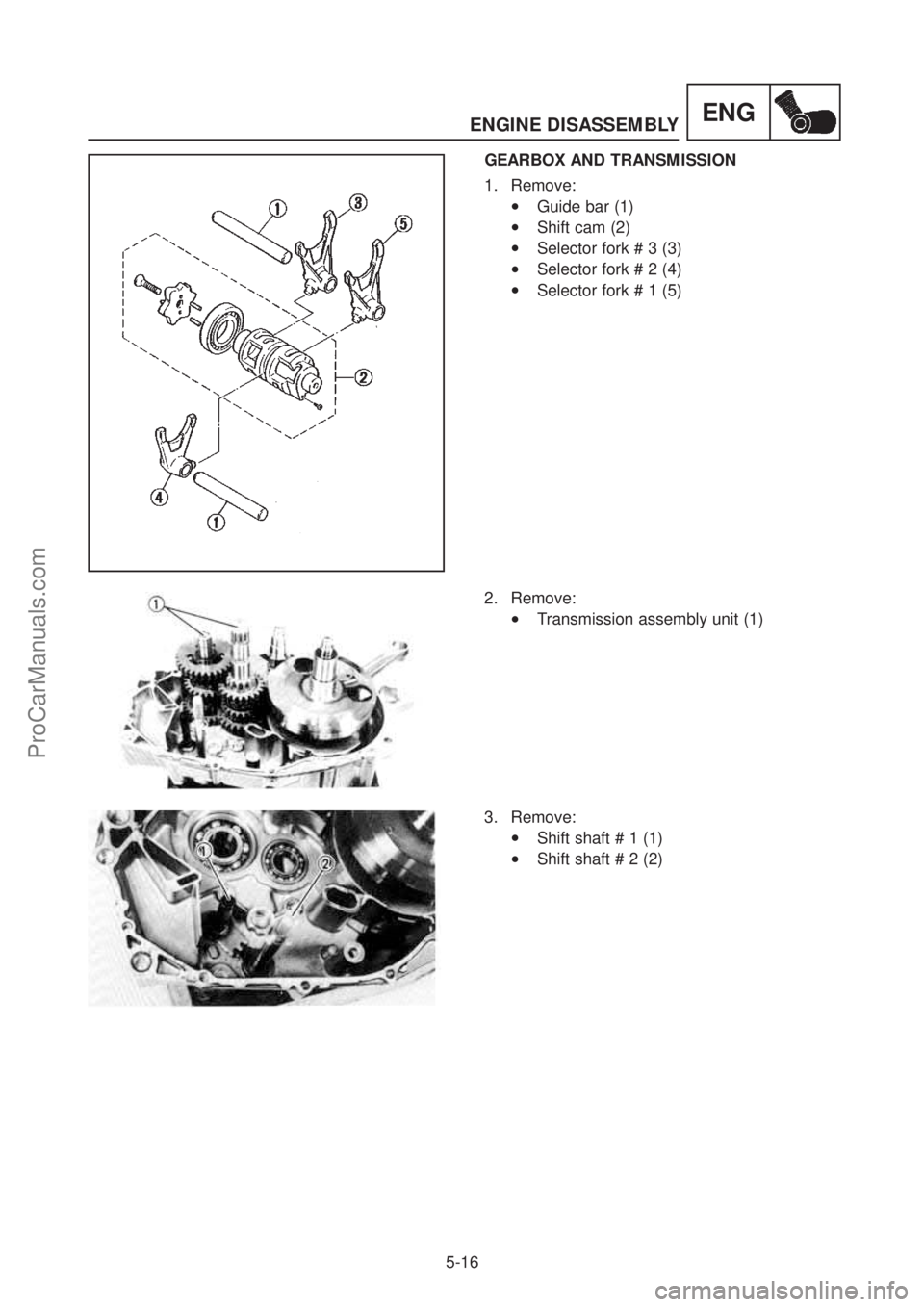
GEARBOX AND TRANSMISSION
1. Remove:
•Guide bar (1)
•Shift cam (2)
•Selector fork # 3 (3)
•Selector fork # 2 (4)
•Selector fork # 1 (5)
2. Remove:
•Transmission assembly unit (1)
3. Remove:
•Shift shaft # 1 (1)
•Shift shaft # 2 (2)
ProCarManuals.com
Trending: wiring, remove seats, engine oil, fuel, maintenance, clock setting, wheel size


