YAMAHA TTR110 2009 Manual PDF
Manufacturer: YAMAHA, Model Year: 2009, Model line: TTR110, Model: YAMAHA TTR110 2009Pages: 76, PDF Size: 2.29 MB
Page 71 of 76
SPECIFICATIONS
8-2
8
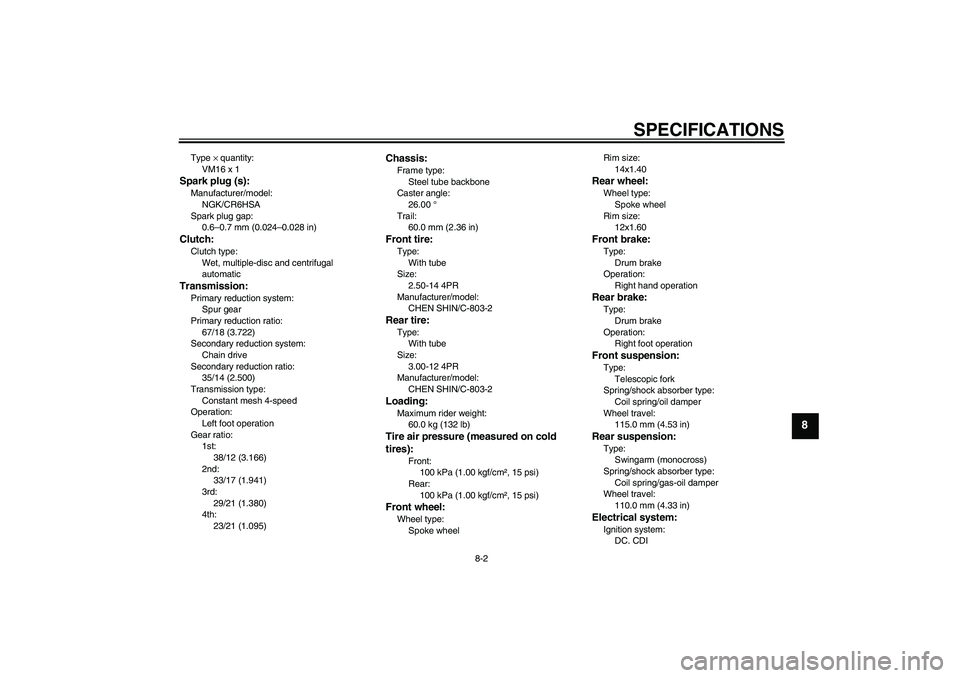
Type × quantity:
VM16 x 1Spark plug (s):Manufacturer/model:
NGK/CR6HSA
Spark plug gap:
0.6–0.7 mm (0.024–0.028 in)Clutch:Clutch type:
Wet, multiple-disc and centrifugal
automaticTransmission:Primary reduction system:
Spur gear
Primary reduction ratio:
67/18 (3.722)
Secondary reduction system:
Chain drive
Secondary reduction ratio:
35/14 (2.500)
Transmission type:
Constant mesh 4-speed
Operation:
Left foot operation
Gear ratio:
1st:
38/12 (3.166)
2nd:
33/17 (1.941)
3rd:
29/21 (1.380)
4th:
23/21 (1.095)
Chassis:Frame type:
Steel tube backbone
Caster angle:
26.00 °
Trail:
60.0 mm (2.36 in)Front tire:Type:
With tube
Size:
2.50-14 4PR
Manufacturer/model:
CHEN SHIN/C-803-2Rear tire:Type:
With tube
Size:
3.00-12 4PR
Manufacturer/model:
CHEN SHIN/C-803-2Loading:Maximum rider weight:
60.0 kg (132 lb)Tire air pressure (measured on cold
tires):
Front:
100 kPa (1.00 kgf/cm², 15 psi)
Rear:
100 kPa (1.00 kgf/cm², 15 psi)
Front wheel:Wheel type:
Spoke wheelRim size:
14x1.40
Rear wheel:Wheel type:
Spoke wheel
Rim size:
12x1.60Front brake:Type:
Drum brake
Operation:
Right hand operationRear brake:Type:
Drum brake
Operation:
Right foot operationFront suspension:Type:
Telescopic fork
Spring/shock absorber type:
Coil spring/oil damper
Wheel travel:
115.0 mm (4.53 in)Rear suspension:Type:
Swingarm (monocross)
Spring/shock absorber type:
Coil spring/gas-oil damper
Wheel travel:
110.0 mm (4.33 in)Electrical system:Ignition system:
DC. CDI
U5B681E0.book Page 2 Tuesday, June 17, 2008 5:48 PM
Page 72 of 76
SPECIFICATIONS
8-3
8
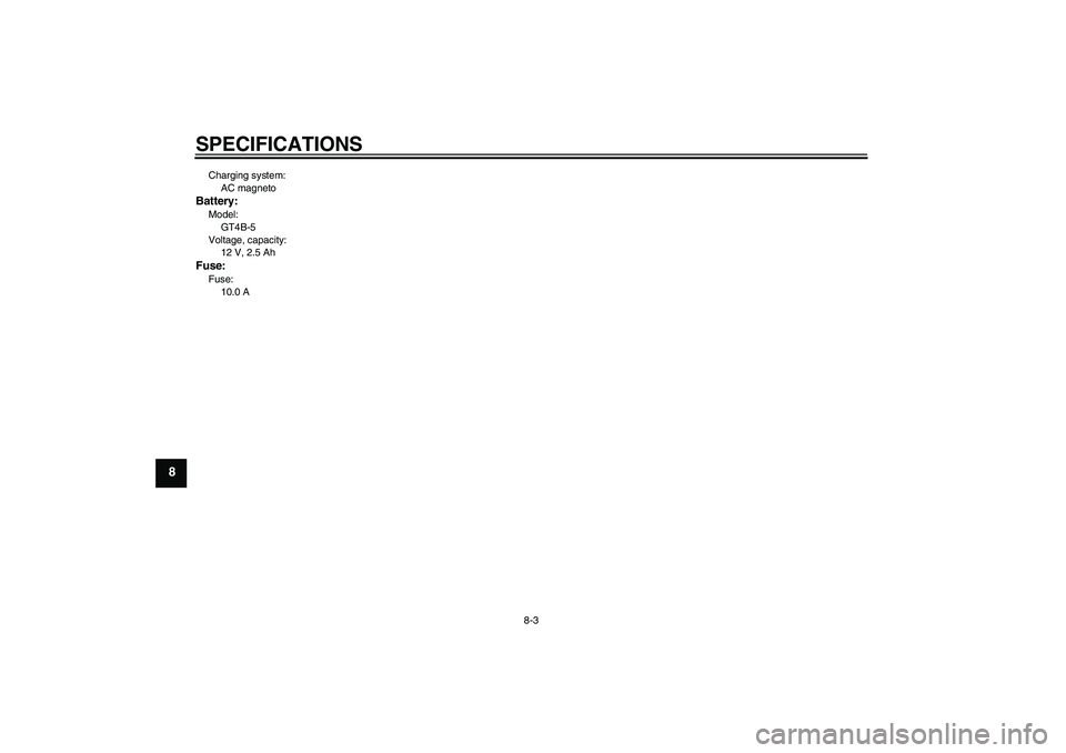
Charging system:
AC magnetoBattery:Model:
GT4B-5
Voltage, capacity:
12 V, 2.5 AhFuse:Fuse:
10.0 A
U5B681E0.book Page 3 Tuesday, June 17, 2008 5:48 PM
Page 73 of 76
CONSUMER INFORMATION
9-1
9
EAU26351
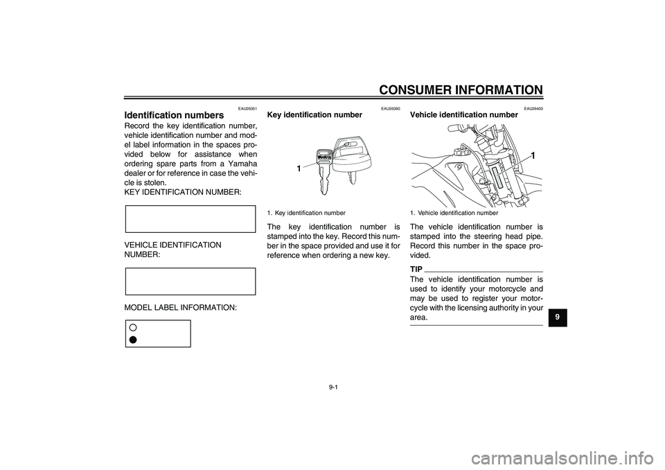
Identification numbers Record the key identification number,
vehicle identification number and mod-
el label information in the spaces pro-
vided below for assistance when
ordering spare parts from a Yamaha
dealer or for reference in case the vehi-
cle is stolen.
KEY IDENTIFICATION NUMBER:
VEHICLE IDENTIFICATION
NUMBER:
MODEL LABEL INFORMATION:
EAU26390
Key identification number
The key identification number is
stamped into the key. Record this num-
ber in the space provided and use it for
reference when ordering a new key.
EAU26400
Vehicle identification number
The vehicle identification number is
stamped into the steering head pipe.
Record this number in the space pro-
vided.TIPThe vehicle identification number is
used to identify your motorcycle and
may be used to register your motor-
cycle with the licensing authority in yourarea.
1. Key identification number
1. Vehicle identification number
1
U5B681E0.book Page 1 Tuesday, June 17, 2008 5:48 PM
Page 74 of 76
CONSUMER INFORMATION
9-2
9
EAU36980
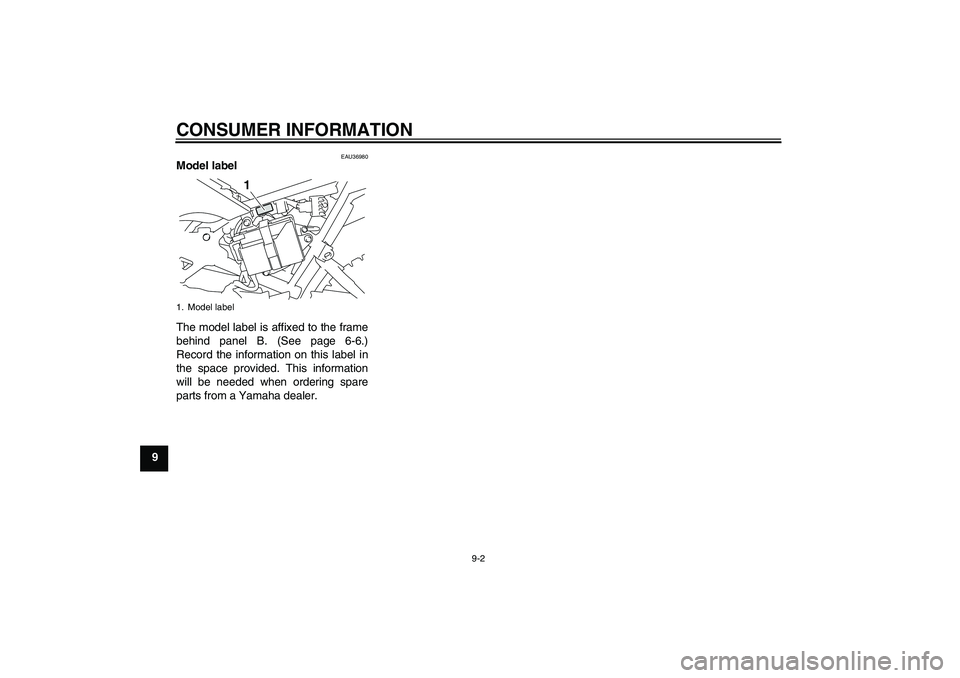
Model label
The model label is affixed to the frame
behind panel B. (See page 6-6.)
Record the information on this label in
the space provided. This information
will be needed when ordering spare
parts from a Yamaha dealer.1. Model label
1
U5B681E0.book Page 2 Tuesday, June 17, 2008 5:48 PM
Page 75 of 76
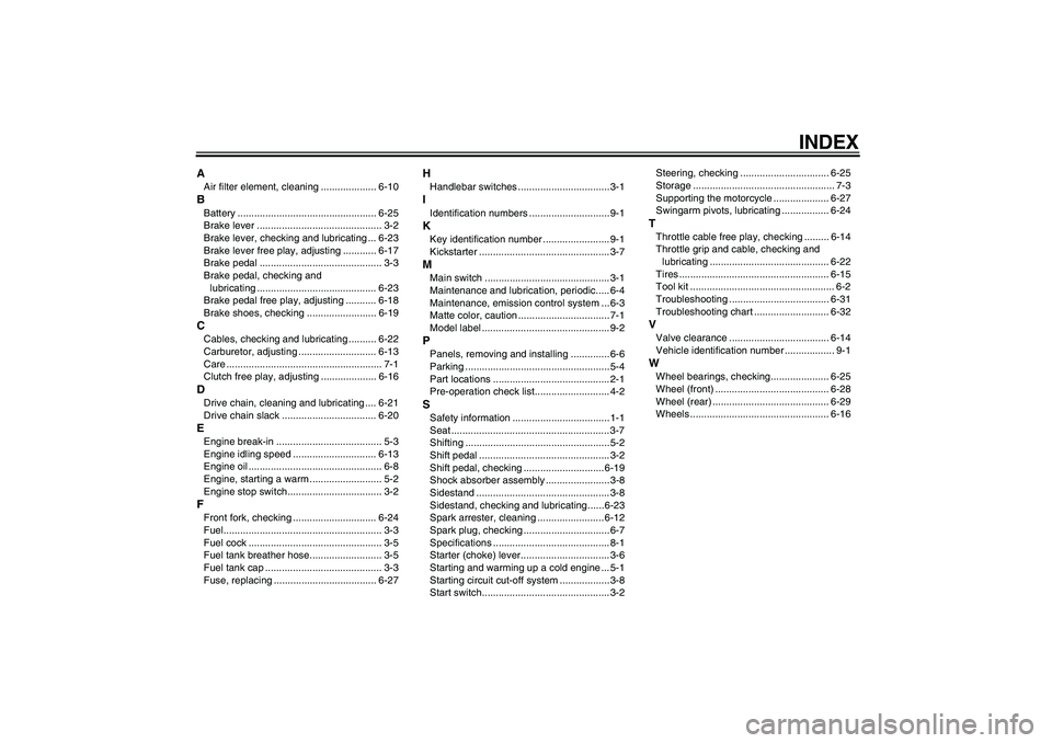
INDEX
AAir filter element, cleaning .................... 6-10BBattery .................................................. 6-25
Brake lever ............................................. 3-2
Brake lever, checking and lubricating ... 6-23
Brake lever free play, adjusting ............ 6-17
Brake pedal ............................................ 3-3
Brake pedal, checking and
lubricating ........................................... 6-23
Brake pedal free play, adjusting ........... 6-18
Brake shoes, checking ......................... 6-19CCables, checking and lubricating .......... 6-22
Carburetor, adjusting ............................ 6-13
Care ........................................................ 7-1
Clutch free play, adjusting .................... 6-16DDrive chain, cleaning and lubricating .... 6-21
Drive chain slack .................................. 6-20EEngine break-in ...................................... 5-3
Engine idling speed .............................. 6-13
Engine oil ................................................ 6-8
Engine, starting a warm .......................... 5-2
Engine stop switch.................................. 3-2FFront fork, checking .............................. 6-24
Fuel......................................................... 3-3
Fuel cock ................................................ 3-5
Fuel tank breather hose.......................... 3-5
Fuel tank cap .......................................... 3-3
Fuse, replacing ..................................... 6-27
HHandlebar switches ................................. 3-1IIdentification numbers ............................. 9-1KKey identification number ........................ 9-1
Kickstarter ............................................... 3-7MMain switch ............................................. 3-1
Maintenance and lubrication, periodic..... 6-4
Maintenance, emission control system ... 6-3
Matte color, caution .................................7-1
Model label .............................................. 9-2PPanels, removing and installing .............. 6-6
Parking ....................................................5-4
Part locations .......................................... 2-1
Pre-operation check list........................... 4-2SSafety information ...................................1-1
Seat ......................................................... 3-7
Shifting ....................................................5-2
Shift pedal ............................................... 3-2
Shift pedal, checking ............................. 6-19
Shock absorber assembly ....................... 3-8
Sidestand ................................................ 3-8
Sidestand, checking and lubricating...... 6-23
Spark arrester, cleaning ........................ 6-12
Spark plug, checking ...............................6-7
Specifications .......................................... 8-1
Starter (choke) lever................................ 3-6
Starting and warming up a cold engine ... 5-1
Starting circuit cut-off system .................. 3-8
Start switch.............................................. 3-2Steering, checking ................................ 6-25
Storage ................................................... 7-3
Supporting the motorcycle .................... 6-27
Swingarm pivots, lubricating ................. 6-24
TThrottle cable free play, checking ......... 6-14
Throttle grip and cable, checking and
lubricating ........................................... 6-22
Tires ...................................................... 6-15
Tool kit .................................................... 6-2
Troubleshooting .................................... 6-31
Troubleshooting chart ........................... 6-32VValve clearance .................................... 6-14
Vehicle identification number .................. 9-1WWheel bearings, checking..................... 6-25
Wheel (front) ......................................... 6-28
Wheel (rear) .......................................... 6-29
Wheels .................................................. 6-16
U5B681E0.book Page 1 Tuesday, June 17, 2008 5:48 PM
Page 76 of 76
YAMAHA MOTOR CO., LTD.
PRINTED ON RECYCLED PAPERPRINTED IN JAPAN
2008.06-1.1×1 CR
(E)
U5B681E0.book Page 1 Tuesday, June 17, 2008 5:48 PM