YAMAHA TTR50 2006 Notices Demploi (in French)
Manufacturer: YAMAHA, Model Year: 2006, Model line: TTR50, Model: YAMAHA TTR50 2006Pages: 390, PDF Size: 9.69 MB
Page 291 of 390
ENG
4 - 52
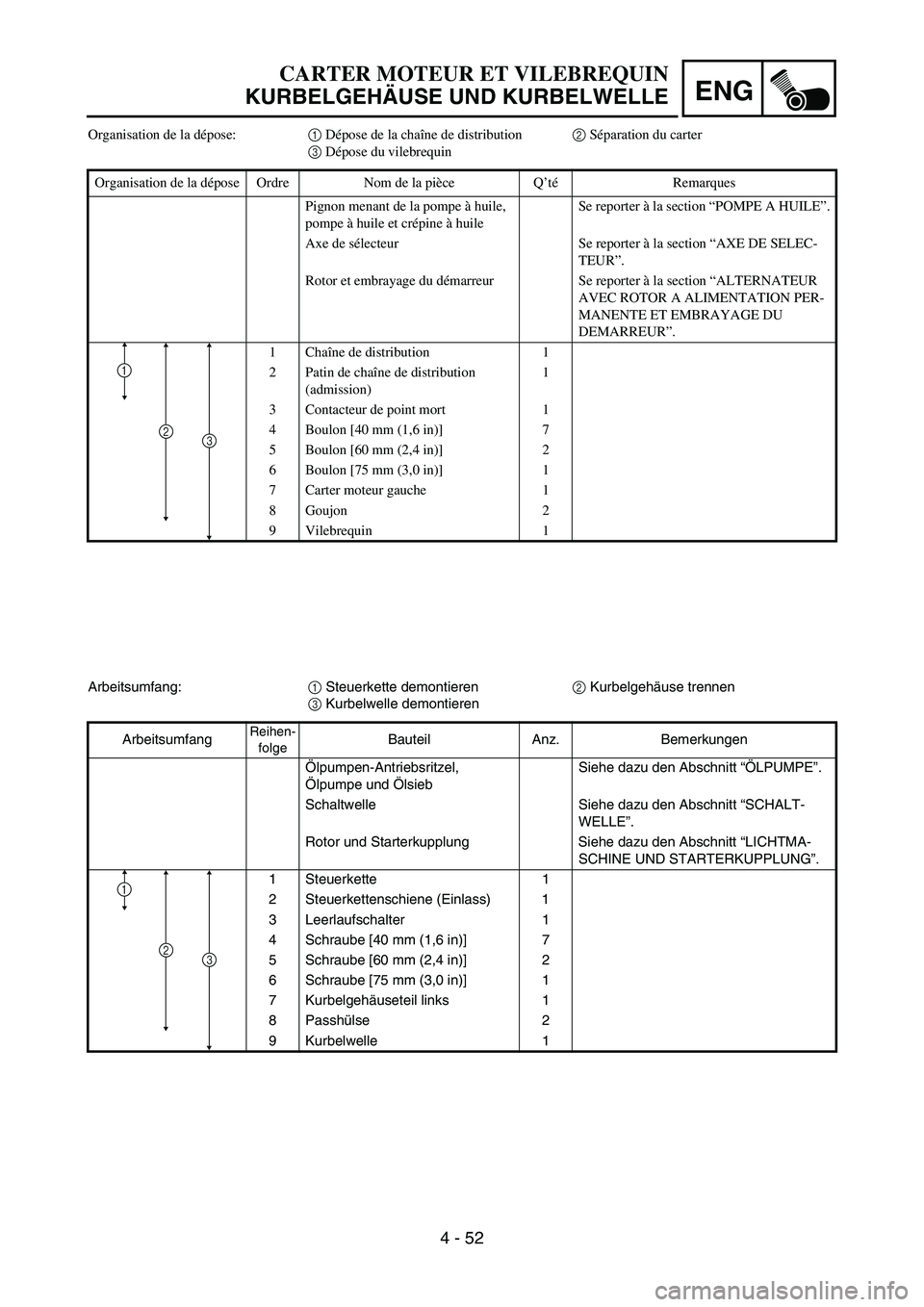
Arbeitsumfang:1 Steuerkette demontieren
2 Kurbelgeh
äuse trennen
3 Kurbelwelle demontieren
Arbeitsumfang
Reihen- folgeBauteil Anz. Bemerkungen
Ö lpumpen-Antriebsritzel,
Ö lpumpe und Ölsieb Siehe dazu den Abschnitt
“ÖLPUMPE ”.
Schaltwelle Siehe dazu den Abschnitt “SCHALT-
WELLE ”.
Rotor und Starterkupplung Siehe dazu den Abschnitt “LICHTMA-
SCHINE UND STARTERKUPPLUNG ”.
1 Steuerkette 1
2 Steuerkettenschiene (Einlass) 1
3 Leerlaufschalter 1
4 Schraube [40 mm (1,6 in)] 7
5 Schraube [60 mm (2,4 in)] 2
6 Schraube [75 mm (3,0 in)] 1
7 Kurbelgeh äuseteil links 1
8 Passh ülse 2
9 Kurbelwelle 1
2
1
3
CARTER MOTEUR ET VILEBREQUIN
KURBELGEH ÄUSE UND KURBELWELLE
Organisation de la d épose: 1 Dépose de la cha îne de distribution 2 Séparation du carter
3 Dépose du vilebrequin
Organisation de la d épose Ordre Nom de la pi èce Q ’té Remarques
Pignon menant de la pompe à huile,
pompe à huile et cr épine à huile Se reporter
à la section “POMPE A HUILE ”.
Axe de s électeur Se reporter à la section “AXE DE SELEC-
TEUR ”.
Rotor et embrayage du d émarreur Se reporter à la section “ALTERNATEUR
AVEC ROTOR A ALIMENTATION PER-
MANENTE ET EMBRAYAGE DU
DEMARREUR ”.
1Cha îne de distribution 1
2 Patin de cha îne de distribution
(admission) 1
3 Contacteur de point mort 1
4 Boulon [40 mm (1,6 in)] 7
5 Boulon [60 mm (2,4 in)] 2
6 Boulon [75 mm (3,0 in)] 1
7 Carter moteur gauche 1
8 Goujon 2
9 Vilebrequin 1
2
1
3
Page 292 of 390

4 - 53
ENGCRANKCASE AND CRANKSHAFT
INSPECTION
Crankshaft
1. Measure:Runout limit a
Connecting rod big end side clearance b
Connecting rod big end radial clearance
c
Crank width d
Out of specification → Replace.
Use the dial gauge and a thickness
gauge.
Standard Limit
Runout
limit —0.03 mm
(0.0012 in)
Side
clearance 0.10 ~ 0.40 mm
(0.0039 ~ 0.0157 in) 0.50 mm
(0.02 in)
Radial
clearance 0.010 ~ 0.025 mm
(0.0004 ~ 0.0010 in) 0.05 mm
(0.002 in)
Crack
width 42.95 ~ 43.00 mm
(1.691 ~ 1.693 in) —
ASSEMBLY AND INSTALLATION
Crankcase
1. Apply:
Sealant
On the left crankcase.
NOTE:
Clean the contacting surface of crankcase
(left and right) before applying the sealant.
DO NOT ALLOW any sealant to come in
contact with the oil gallery a.
Yamaha bond No. 1215:
90890-85505
a
Page 293 of 390
4 - 53
ENG
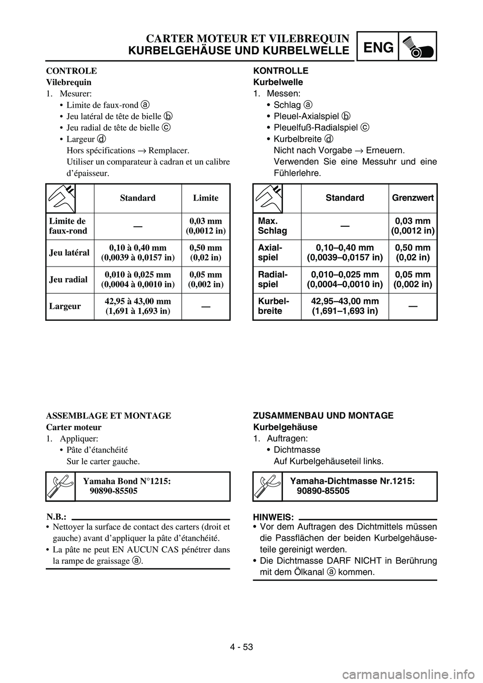
KONTROLLE
Kurbelwelle
1. Messen:Schlag a
Pleuel-Axialspiel b
Pleuelfu ß-Radialspiel c
Kurbelbreite d
Nicht nach Vorgabe → Erneuern.
Verwenden Sie eine Messuhr und eine
F ühlerlehre.
Standard Grenzwert
Max.
Schlag —0,03 mm
(0,0012 in)
Axial-
spiel 0,10
–0,40 mm
(0,0039 –0,0157 in) 0,50 mm
(0,02 in)
Radial-
spiel 0,010
–0,025 mm
(0,0004 –0,0010 in) 0,05 mm
(0,002 in)
Kurbel-
breite 42,95
–43,00 mm
(1,691 –1,693 in) —
ZUSAMMENBAU UND MONTAGE
Kurbelgeh
äuse
1. Auftragen: Dichtmasse
Auf Kurbelgeh äuseteil links.
HINWEIS:
Vor dem Auftragen des Dichtmittels m üssen
die Passfl ächen der beiden Kurbelgeh äuse-
teile gereinigt werden.
Die Dichtmasse DARF NICHT in Ber ührung
mit dem Ölkanal a kommen.
Yamaha-Dichtmasse Nr.1215:
90890-85505
CARTER MOTEUR ET VILEBREQUIN
KURBELGEH ÄUSE UND KURBELWELLE
CONTROLE
Vilebrequin
1. Mesurer:
Limite de faux-rond a
Jeu lat éral de t ête de bielle b
Jeu radial de t ête de bielle c
Largeur d
Hors sp écifications → Remplacer.
Utiliser un comparateur à cadran et un calibre
d ’é paisseur.
Standard Limite
Limite de
faux-rond —0,03 mm
(0,0012 in)
Jeu lat éral 0,10
à 0,40 mm
(0,0039 à 0,0157 in) 0,50 mm
(0,02 in)
Jeu radial 0,010
à 0,025 mm
(0,0004 à 0,0010 in) 0,05 mm
(0,002 in)
Largeur 42,95
à 43,00 mm
(1,691 à 1,693 in) —
ASSEMBLAGE ET MONTAGE
Carter moteur
1. Appliquer:
Pâte d ’étanch éit é
Sur le carter gauche.
N.B.:
Nettoyer la surface de contact des carters (droit et
gauche) avant d ’appliquer la p âte d ’étanch éit é.
La p âte ne peut EN AUCUN CAS p én étrer dans
la rampe de graissage a.
Yamaha Bond N °1215:
90890-85505
Page 294 of 390
4 - 54
ENGSHIFT FORK, SHIFT CAM AND TRANSMISSION
SHIFT FORK, SHIFT CAM AND TRANSMISSION
0.8~1.3mm
(0.03~0.05 in)
New
New
New
New
M
M
12 13 14
15 16
17 18
19
7
8
9
10
11
4 3
1
2
M
E
5 6
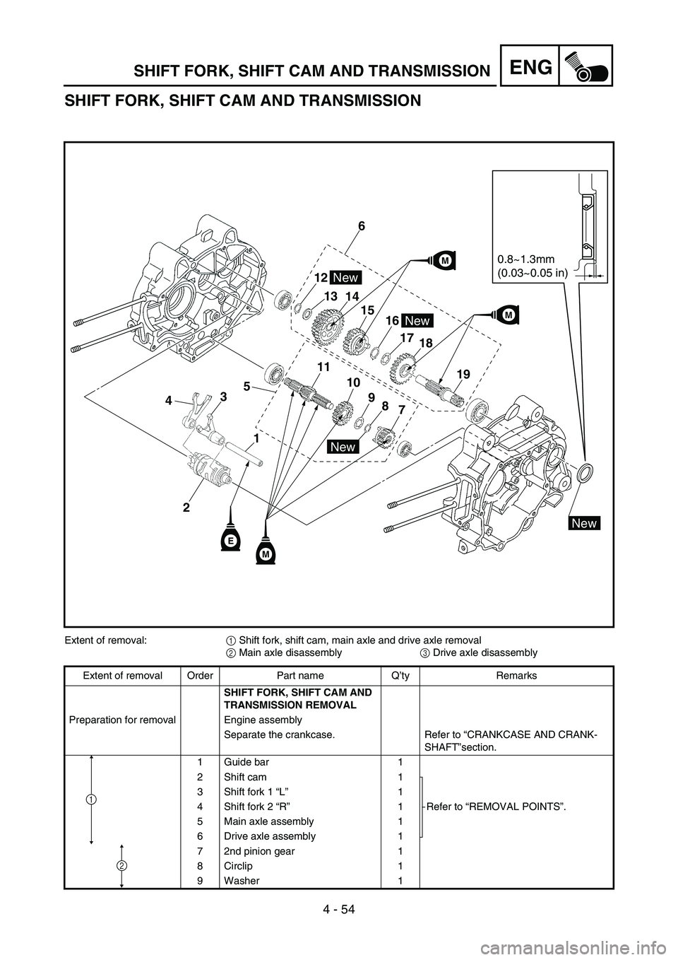
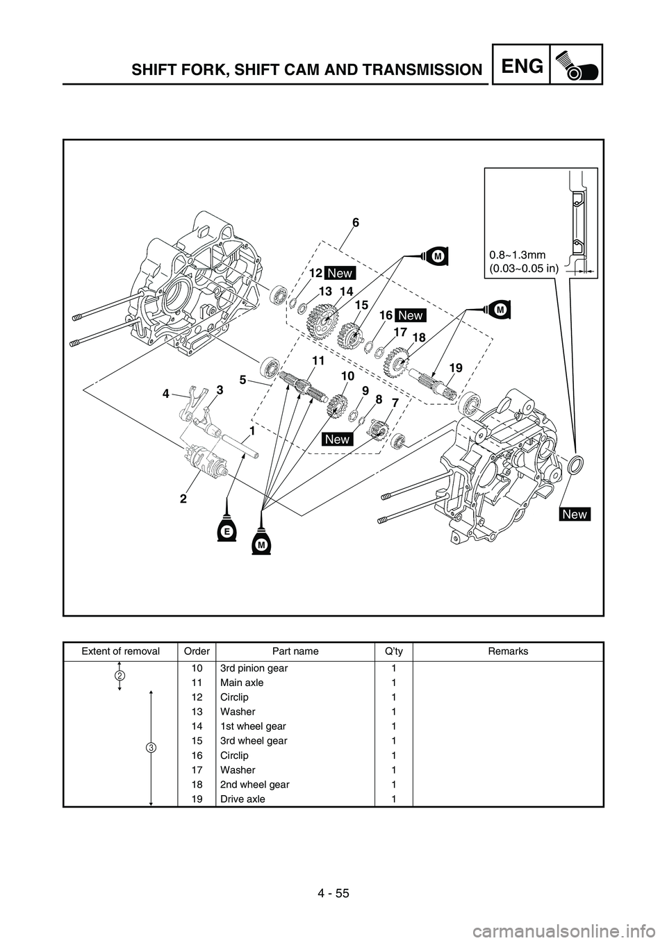
Extent of removal:
1 Shift fork, shift cam, main axle and drive axle removal
2 Main axle disassembly
3 Drive axle disassembly
Extent of removal Order Part name Q ’ty Remarks
SHIFT FORK, SHIFT CAM AND
TRANSMISSION REMOVAL
Preparation for removal Engine assembly Separate the crankcase. Refer to “CRANKCASE AND CRANK-
SHAFT ”section.
1 Guide bar 1
2Shift cam 1
Refer to “REMOVAL POINTS ”.
3 Shift fork 1
“L ” 1
4 Shift fork 2 “R ” 1
5 Main axle assembly 1
6 Drive axle assembly 1
7 2nd pinion gear 1
8 Circlip 1
9 Washer 1
2
1
Page 295 of 390
ENG
4 - 54
SCHALTGABELN, SCHALTWALZE UND GETRIEBE
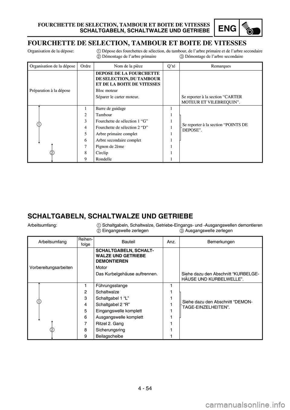
Arbeitsumfang:1 Schaltgabeln, Schaltwalze, Getriebe-Eingangs- und -Ausgangswellen demontieren
2 Eingangswelle zerlegen
3 Ausgangswelle zerlegen
Arbeitsumfang
Reihen- folgeBauteil Anz. Bemerkungen
SCHALTGABELN, SCHALT-
WALZE UND GETRIEBE
DEMONTIEREN
Vorbereitungsarbeiten Motor
Das Kurbelgehäuse auftrennen. Siehe dazu den Abschnitt “KURBELGE-
H ÄUSE UND KURBELWELLE ”.
1F ührungsstange 1
2 Schaltwalze 1
Siehe dazu den Abschnitt “DEMON-
TAGE-EINZELHEITEN ”.
3 Schaltgabel 1
“L ” 1
4 Schaltgabel 2 “R ” 1
5 Eingangswelle komplett 1
6 Ausgangswelle komplett 1
7 Ritzel 2. Gang 1
8 Sicherungsring 1
9 Beilagscheibe 1
2
1
FOURCHETTE DE SELECTION, TAMBOUR ET BOITE DE VITESSES SCHALTGABELN, SCHALTWALZE UND GETRIEBE
FOURCHETTE DE SELECTION, TAMBOUR ET BOITE DE VITESSES
Organisation de la d épose: 1 Dépose des fourchettes de s élection, du tambour, de l ’arbre primaire et de l ’arbre secondaire
2 Démontage de l ’arbre primaire 3 Démontage de l ’arbre secondaire
Organisation de la d épose Ordre Nom de la pi èce Q ’té Remarques
DEPOSE DE LA FOURCHETTE
DE SELECTION, DU TAMBOUR
ET DE LA BOITE DE VITESSES
Pr éparation à la d épose Bloc moteur
Séparer le carter moteur. Se reporter à la section “CARTER
MOTEUR ET VILEBREQUIN ”.
1 Barre de guidage 1
2 Tambour 1
Se reporter à la section “POINTS DE
DEPOSE ”.
3 Fourchette de s
élection 1 “G ” 1
4 Fourchette de s élection 2 “D ” 1
5 Arbre primaire complet 1
6 Arbre secondaire complet 1
7 Pignon de 2 ème 1
8Circlip 1
9 Rondelle 1
2
1
Page 296 of 390
4 - 55
ENGSHIFT FORK, SHIFT CAM AND TRANSMISSION
0.8~1.3mm
(0.03~0.05 in)
New
New
New
New
M
M
1213 14
15 16
17 18
19
7
8
9
10
11
4 3
1
2
M
E
5 6
Extent of removal Order Part name Q
’ty Remarks
10 3rd pinion gear 1
11 Main axle 1
12 Circlip 1
13 Washer 1
14 1st wheel gear 1
15 3rd wheel gear 1
16 Circlip 1
17 Washer 1
18 2nd wheel gear 1
19 Drive axle 1
2
3
Page 297 of 390
ENG
4 - 55
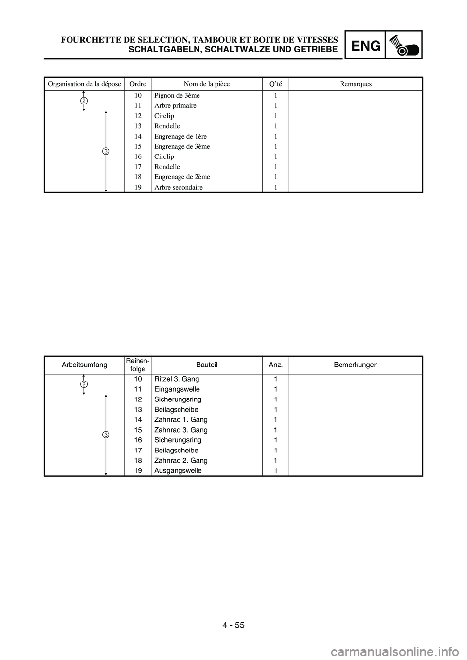
ArbeitsumfangReihen-folgeBauteil Anz. Bemerkungen
10 Ritzel 3. Gang 1
11 Eingangswelle 1
12 Sicherungsring 1
13 Beilagscheibe 1
14 Zahnrad 1. Gang 1
15 Zahnrad 3. Gang 1
16 Sicherungsring 1
17 Beilagscheibe 1
18 Zahnrad 2. Gang 1
19 Ausgangswelle 1
2
3
FOURCHETTE DE SELECTION, TAMBOUR ET BOITE DE VITESSES SCHALTGABELN, SCHALTWALZE UND GETRIEBE
Organisation de la d épose Ordre Nom de la pi èce Q ’té Remarques
10 Pignon de 3 ème 1
11 Arbre primaire 1
12 Circlip 1
13 Rondelle 1
14 Engrenage de 1 ère 1
15 Engrenage de 3 ème 1
16 Circlip 1
17 Rondelle 1
18 Engrenage de 2 ème 1
19 Arbre secondaire 1
2
3
Page 298 of 390
4 - 56
ENGSHIFT FORK, SHIFT CAM AND TRANSMISSION
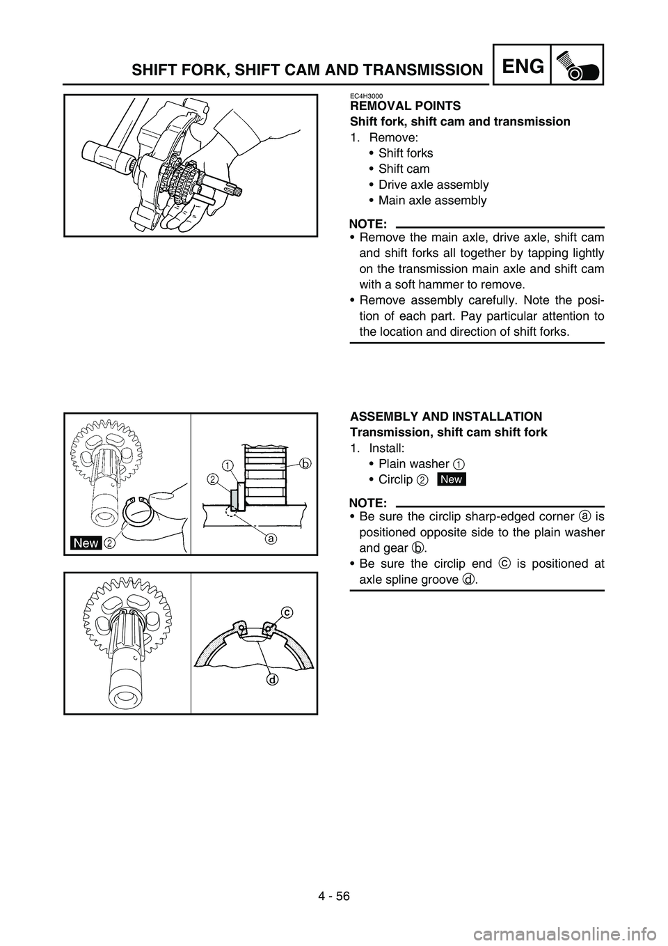
EC4H3000
REMOVAL POINTS
Shift fork, shift cam and transmission
1. Remove:Shift forks
Shift cam
Drive axle assembly
Main axle assembly
NOTE:
Remove the main axle, drive axle, shift cam
and shift forks all together by tapping lightly
on the transmission main axle and shift cam
with a soft hammer to remove.
Remove assembly carefully. Note the posi-
tion of each part. Pay particular attention to
the location and direction of shift forks.
ASSEMBLY AND INSTALLATION
Transmission, shift cam shift fork
1. Install:
Plain washer 1
Circlip 2
NOTE:
Be sure the circlip sharp-edged corner a is
positioned opposite side to the plain washer
and gear b.
Be sure the circlip end c is positioned at
axle spline groove d.
New
Page 299 of 390
4 - 56
ENG
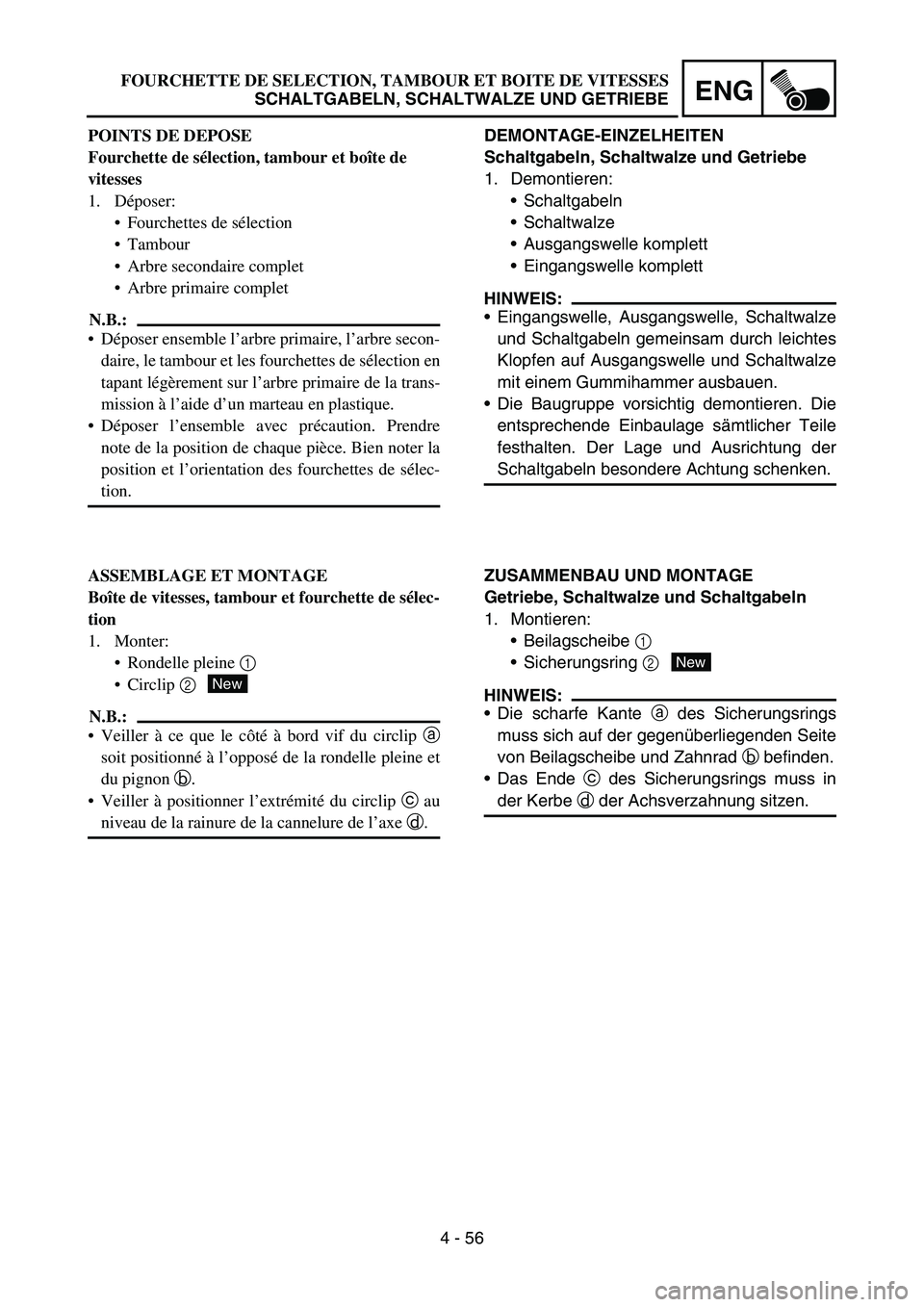
DEMONTAGE-EINZELHEITEN
Schaltgabeln, Schaltwalze und Getriebe
1. Demontieren:Schaltgabeln
Schaltwalze
Ausgangswelle komplett
Eingangswelle komplett
HINWEIS:
Eingangswelle, Ausgangswelle, Schaltwalze
und Schaltgabeln gemeinsam durch leichtes
Klopfen auf Ausgangswelle und Schaltwalze
mit einem Gummihammer ausbauen.
Die Baugruppe vorsichtig demontieren. Die
entsprechende Einbaulage s ämtlicher Teile
festhalten. Der Lage und Ausrichtung der
Schaltgabeln besondere Achtung schenken.
ZUSAMMENBAU UND MONTAGE
Getriebe, Schaltwalze und Schaltgabeln
1. Montieren: Beilagscheibe 1
Sicherungsring 2
HINWEIS:
Die scharfe Kante a des Sicherungsrings
muss sich auf der gegen überliegenden Seite
von Beilagscheibe und Zahnrad b befinden.
Das Ende c des Sicherungsrings muss in
der Kerbe d der Achsverzahnung sitzen.
New
FOURCHETTE DE SELECTION, TAMBOUR ET BOITE DE VITESSES
SCHALTGABELN, SCHALTWALZE UND GETRIEBE
POINTS DE DEPOSE
Fourchette de s élection, tambour et bo îte de
vitesses
1. D époser:
Fourchettes de s élection
Tambour
Arbre secondaire complet
Arbre primaire complet
N.B.:
Déposer ensemble l ’arbre primaire, l ’arbre secon-
daire, le tambour et les fourchettes de s élection en
tapant l ég èrement sur l ’arbre primaire de la trans-
mission à l ’aide d ’un marteau en plastique.
Déposer l ’ensemble avec pr écaution. Prendre
note de la position de chaque pi èce. Bien noter la
position et l ’orientation des fourchettes de s élec-
tion.
ASSEMBLAGE ET MONTAGE
Bo îte de vitesses, tambour et fourchette de s élec-
tion
1. Monter: Rondelle pleine 1
Circlip 2
N.B.:
Veiller à ce que le c ôté à bord vif du circlip a
soit positionn é à l ’oppos é de la rondelle pleine et
du pignon b.
Veiller à positionner l ’extr émit é du circlip c au
niveau de la rainure de la cannelure de l ’axe d.
New
Page 300 of 390
4 - 57
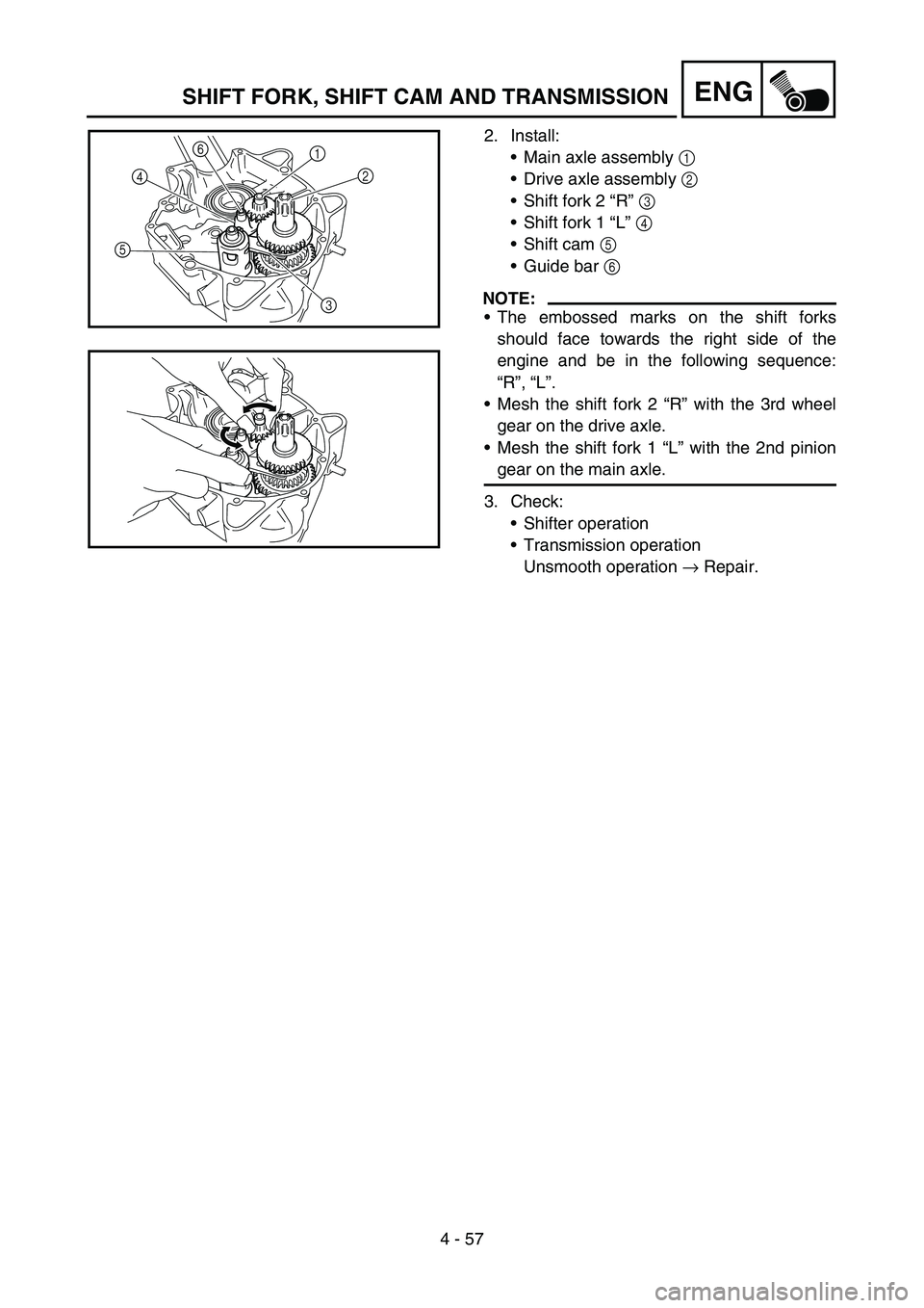
ENGSHIFT FORK, SHIFT CAM AND TRANSMISSION
2. Install:Main axle assembly 1
Drive axle assembly 2
Shift fork 2 “R ” 3
Shift fork 1 “L ” 4
Shift cam 5
Guide bar 6
NOTE:
The embossed marks on the shift forks
should face towards the right side of the
engine and be in the following sequence:
“R ”, “L ”.
Mesh the shift fork 2 “R ” with the 3rd wheel
gear on the drive axle.
Mesh the shift fork 1 “L ” with the 2nd pinion
gear on the main axle.
3. Check: Shifter operation
Transmission operation
Unsmooth operation → Repair.
3
4
5 1
6
2