engine YAMAHA TTR90 2006 Betriebsanleitungen (in German)
[x] Cancel search | Manufacturer: YAMAHA, Model Year: 2006, Model line: TTR90, Model: YAMAHA TTR90 2006Pages: 390, PDF-Größe: 9.12 MB
Page 6 of 390
IMPORTANT NOTICE
This machine is designed for off-road use only
by young operators under adult instruction and
supervision. It is illegal for this machine to be
operated on any public street, road, or high-
way.
Off-road use on public lands may be illegal.
Please check local regulations before riding.
1. GASOLINE IS HIGHLY FLAMMABLE:
* Always turn off the engine when
refueling.
* Take care not to spill on the engine
or exhaust pipe/muffler, when refu-
eling.
* Never refuel while smoking or in
the vicinity of an open flame.
2. If you should swallow some gasoline
or inhale a lot of gasoline vapor, or
allow some gasoline to get in your
eye(s), see your doctor immediately.
If any gasoline spills on your skin or
clothing, immediately wash it with
soap and water, and change your
clothes.
3. Always turn off the engine before
leaving the machine unattended.
When parking the machine, note the
following:
* The engine and exhaust pipe(s)/
muffler(s) may be hot. Park the
machine in a place where pedestri-
ans or children are not likely to
touch the machine.
* Do not park the machine on a slope
or soft ground; the machine may
overturn.
SAFETY INFORMATION
Page 8 of 390
4. When transporting the machine in
another vehicle, be sure is kept
upright and that the fuel cock is
turned to the “OFF”. If it should lean
over, gasoline may leak out of the car-
buretor or fuel tank.
5. Never start your engine or let it run
for any length of time in a closed
area. The exhaust fumes are poison-
ous and may cause loss of con-
sciousness and death within a short
time. Always operate your machine in
an area with adequate ventilation.
6. Always wear a helmet, gloves, boots,
trousers, and jacket for motocross
riding.
Page 10 of 390
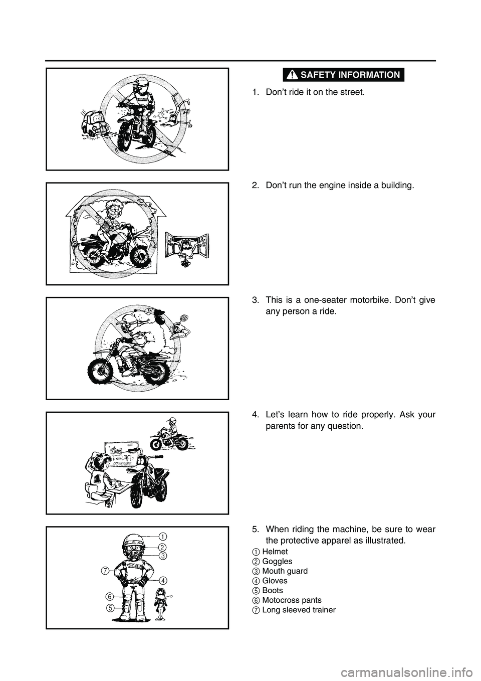
SAFETY INFORMATION
1. Don’t ride it on the street.
2. Don’t run the engine inside a building.
3. This is a one-seater motorbike. Don’t give
any person a ride.
4. Let’s learn how to ride properly. Ask your
parents for any question.
5. When riding the machine, be sure to wear
the protective apparel as illustrated.
1Helmet
2Goggles
3Mouth guard
4Gloves
5Boots
6Motocross pants
7Long sleeved trainer
Page 12 of 390
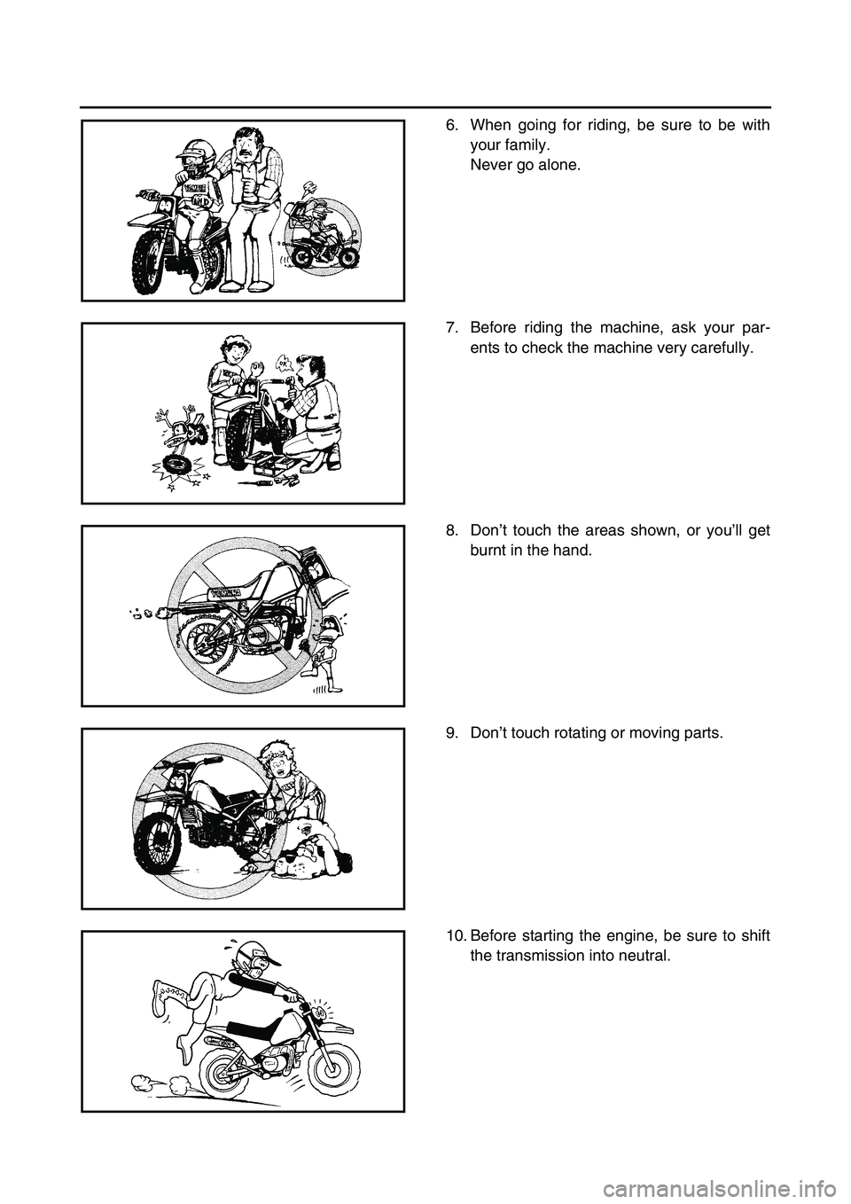
6. When going for riding, be sure to be with
your family.
Never go alone.
7. Before riding the machine, ask your par-
ents to check the machine very carefully.
8. Don’t touch the areas shown, or you’ll get
burnt in the hand.
9. Don’t touch rotating or moving parts.
10. Before starting the engine, be sure to shift
the transmission into neutral.
Page 14 of 390
EC080000
HOW TO USE
THIS MANUAL
EC081000
PARTICULARLY IMPORTANT
INFORMATION
The Safety Alert Symbol means ATTENTION!
BECOME ALERT! YOUR SAFETY IS
INVOLVED!
Failure to follow WARNING instructions could
result in severe injury or death to the machine
operator, a bystander, or a person inspecting
or repairing the machine.
A CAUTION indicates special precautions that
must be taken to avoid damage to the
machine.
NOTE:
A NOTE provides key information to make pro-
cedures easier or clearer.
WARNING
CAUTION:
EC082000
FINDING THE REQUIRED PAGE
1. This manual consists of six chapters; “Gen-
eral Information”, “Specifications”, “Regular
inspection and adjustments”, “Engine”,
“Chassis” and “Electrical”.
2. The table of contents is at the beginning of
the manual. Look over the general layout of
the book before finding then required chap-
ter and item.
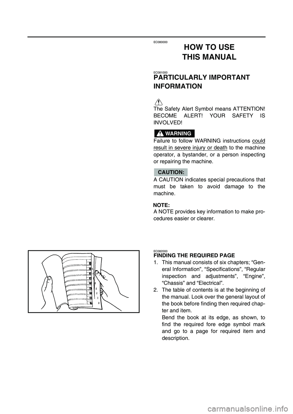
Bend the book at its edge, as shown, to
find the required fore edge symbol mark
and go to a page for required item and
description.
Page 18 of 390
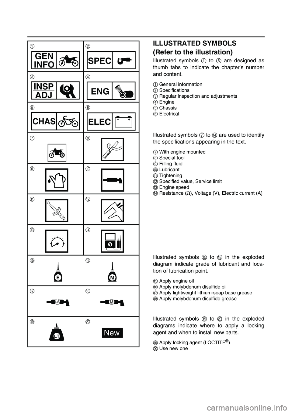
ILLUSTRATED SYMBOLS
(Refer to the illustration)
Illustrated symbols 1 to 6 are designed as
thumb tabs to indicate the chapter’s number
and content.
1General information
2Specifications
3Regular inspection and adjustments
4Engine
5Chassis
6Electrical
Illustrated symbols 7 to D are used to identify
the specifications appearing in the text.
7With engine mounted
8Special tool
9Filling fluid
0Lubricant
ATightening
BSpecified value, Service limit
CEngine speed
DResistance (
Ω), Voltage (V), Electric current (A)
Illustrated symbols E to H in the exploded
diagram indicate grade of lubricant and loca-
tion of lubrication point.
EApply engine oil
FApply molybdenum disulfide oil
GApply lightweight lithium-soap base grease
HApply molybdenum disulfide grease
Illustrated symbols I to J in the exploded
diagrams indicate where to apply a locking
agent and when to install new parts.
IApply locking agent (LOCTITE®)
JUse new one 12
34
56
78
90
AB
CD
E
F
G
H
IJ
GEN
INFOSPEC
INSP
ADJ
ENG
CHAS–+ELEC
T R..
EM
LSM
LTNew
Page 20 of 390
INDEX
GENERAL INFORMATION
SPECIFICATIONS
REGULAR INSPECTION AND ADJUSTMENTS
ENGINE
CHASSIS
ELECTRICAL
Page 22 of 390
CONTENTS
CHAPTER 1
GENERAL INFORMATION
DESCRIPTION ...........................................1-1
MACHINE IDENTIFICATION .....................1-2
IMPORTANT INFORMATION ....................1-3
CHECKING OF CONNECTION .................1-5
SPECIAL TOOLS ......................................1-6
CONTROL FUNCTIONS ............................1-9
FUEL ........................................................1-12
STARTING AND OPERATION ................1-13
CLEANING AND STORAGE ...................1-14
CHAPTER 2
SPECIFICATIONS
GENERAL SPECIFICATIONS ...................2-1
MAINTENANCE SPECIFICATIONS ..........2-4
GENERAL TORQUE
SPECIFICATIONS ...................................2-17
DEFINITION OF UNITS ...........................2-17
CABLE ROUTING DIAGRAM .................2-18
CHAPTER 3
REGULAR INSPECTION AND
ADJUSTMENTS
MAINTENANCE INTERVALS ...................3-1
PRE-OPERATION INSPECTION AND
MAINTENANCE .........................................3-3
ENGINE ......................................................3-4
CHASSIS .................................................3-12
ELECTRICAL ...........................................3-23
Page 24 of 390
CHAPTER 4
ENGINE
CARBURETOR ..........................................4-1
CYLINDER HEAD ......................................4-8
CAMSHAFT AND ROCKER ARMS ........4-13
VALVES AND VALVE SPRINGS ............4-16
CYLINDER AND PISTON ........................4-21
CLUTCH ...................................................4-27
KICK AXLE ..............................................4-33
SHIFT SHAFT ..........................................4-34
OIL PUMP ................................................4-36
CDI MAGNETO (TT-R90) ........................4-39
CDI MAGNETO AND
STARTER CLUTCH (TT-R90E) ...............4-41
CRANKCASE AND CRANKSHAFT ........4-45
SHIFT FORK, SHIFT CAM AND
TRANSMISSION ......................................4-48
CHAPTER 5
CHASSIS
FRONT WHEEL AND REAR WHEEL .......5-1
FRONT FORK ..........................................5-10
HANDLEBAR ...........................................5-13
STEERING ...............................................5-18
SWINGARM .............................................5-20
CHAPTER 6
ELECTRICAL
ELECTRICAL COMPONENTS AND
WIRING DIAGRAM ....................................6-1
IGNITION SYSTEM ....................................6-3
ELECTRIC STARTING SYSTEM
(TT-R90E) ..................................................6-7
CHARGING SYSTEM (TT-R90E) ............6-15
CARBURETOR HEATING SYSTEM .......6-17
MAINTENANCE RECORD ......................6-21
Page 26 of 390
1 - 1
GEN
INFO
DESCRIPTION
EC100000
GENERAL INFORMATION
EC110000
DESCRIPTION
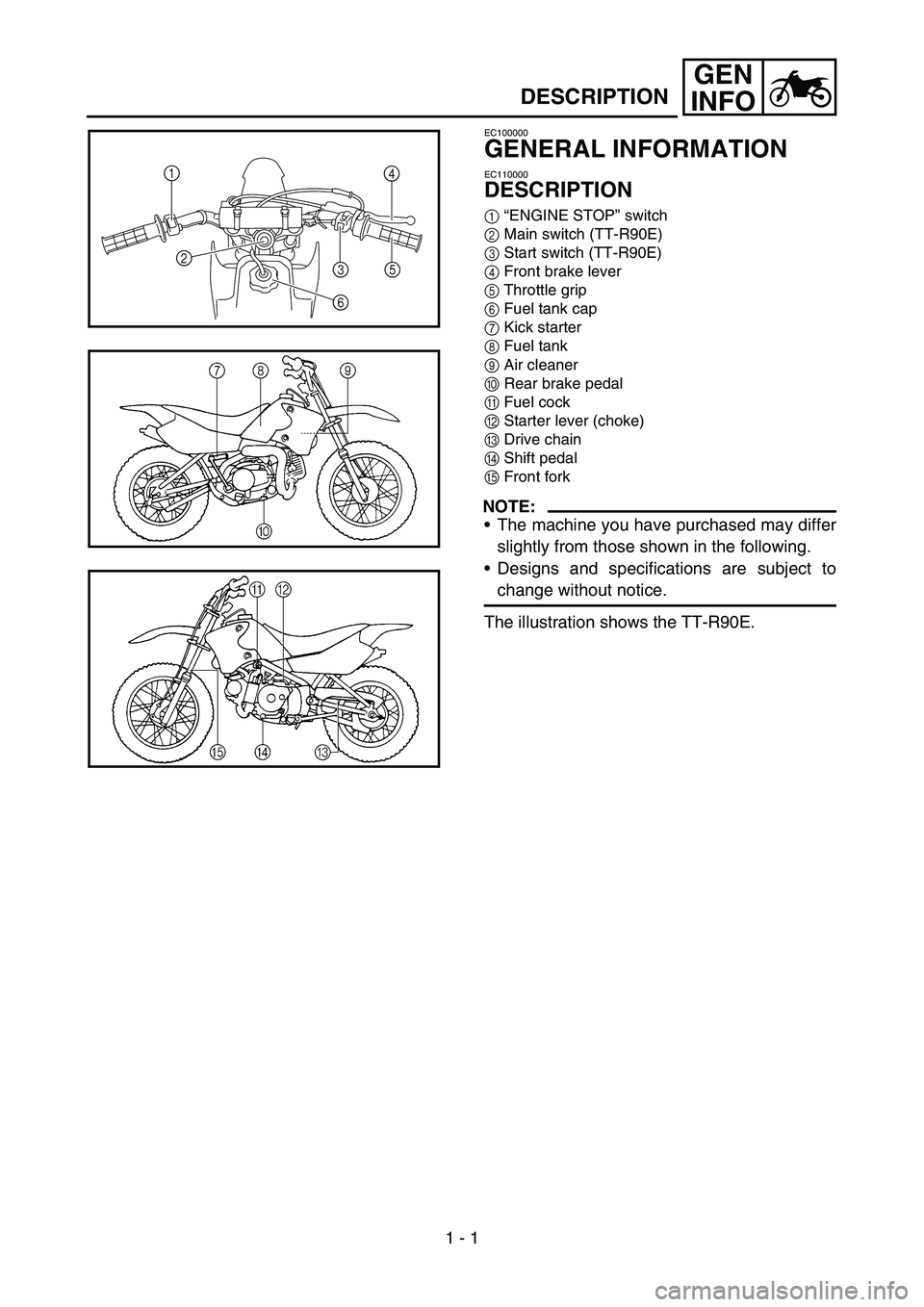
1“ENGINE STOP” switch
2Main switch (TT-R90E)
3Start switch (TT-R90E)
4Front brake lever
5Throttle grip
6Fuel tank cap
7Kick starter
8Fuel tank
9Air cleaner
0Rear brake pedal
AFuel cock
BStarter lever (choke)
CDrive chain
DShift pedal
EFront fork
NOTE:
The machine you have purchased may differ
slightly from those shown in the following.
Designs and specifications are subject to
change without notice.
The illustration shows the TT-R90E.
1
4
5
6
23
1