fuel YAMAHA TTR90 2006 Notices Demploi (in French)
[x] Cancel search | Manufacturer: YAMAHA, Model Year: 2006, Model line: TTR90, Model: YAMAHA TTR90 2006Pages: 390, PDF Size: 9.12 MB
Page 206 of 390
4 - 6
ENGCARBURETOR
EC464600
Float
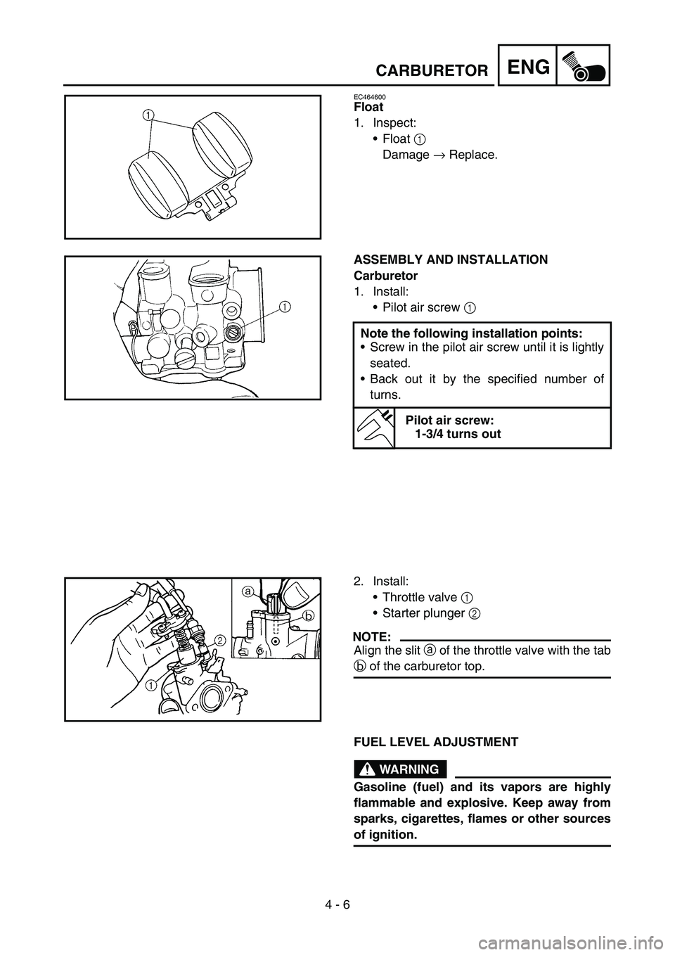
1. Inspect:
Float 1
Damage → Replace.
ASSEMBLY AND INSTALLATION
Carburetor
1. Install:
Pilot air screw 1
Note the following installation points:
Screw in the pilot air screw until it is lightly
seated.
Back out it by the specified number of
turns.
Pilot air screw:
1-3/4 turns out
2. Install:
Throttle valve 1
Starter plunger 2
NOTE:
Align the slit a of the throttle valve with the tab
b of the carburetor top.
FUEL LEVEL ADJUSTMENT
WARNING
Gasoline (fuel) and its vapors are highly
flammable and explosive. Keep away from
sparks, cigarettes, flames or other sources
of ignition.
Page 208 of 390
4 - 7
ENGCARBURETOR
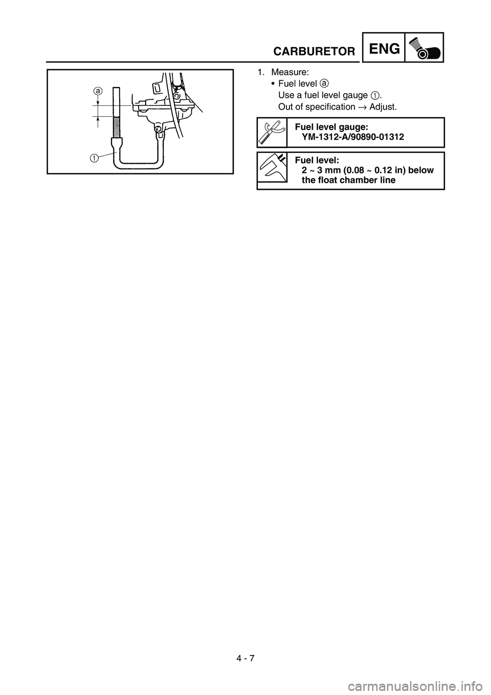
1. Measure:
Fuel level a
Use a fuel level gauge 1.
Out of specification → Adjust.
Fuel level gauge:
YM-1312-A/90890-01312
Fuel level:
2 ~ 3 mm (0.08 ~ 0.12 in) below
the float chamber line
Page 210 of 390
4 - 8
ENGCYLINDER HEAD
CYLINDER HEAD
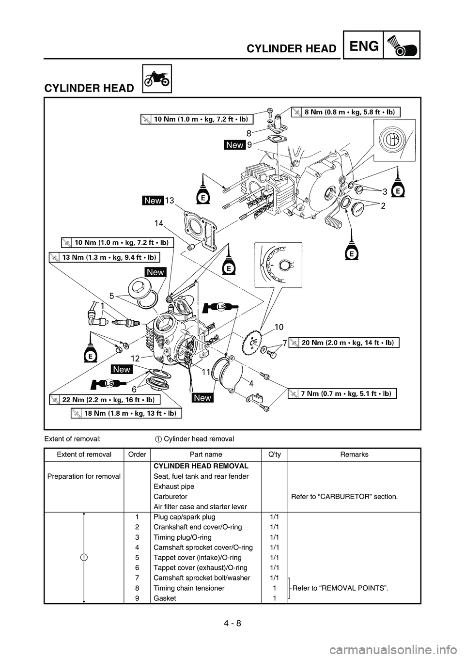
Extent of removal:
1 Cylinder head removal
Extent of removal Order Part name Q’ty Remarks
CYLINDER HEAD REMOVAL
Preparation for removal Seat, fuel tank and rear fender
Exhaust pipe
Carburetor Refer to “CARBURETOR” section.
Air filter case and starter lever
1 Plug cap/spark plug 1/1
2 Crankshaft end cover/O-ring 1/1
3 Timing plug/O-ring 1/1
4 Camshaft sprocket cover/O-ring 1/1
5 Tappet cover (intake)/O-ring 1/1
6 Tappet cover (exhaust)/O-ring 1/1
7 Camshaft sprocket bolt/washer 1/1
Refer to “REMOVAL POINTS”. 8 Timing chain tensioner 1
9 Gasket 1
1
Page 272 of 390
4 - 39
ENG
CDI MAGNETO (TT-R90)
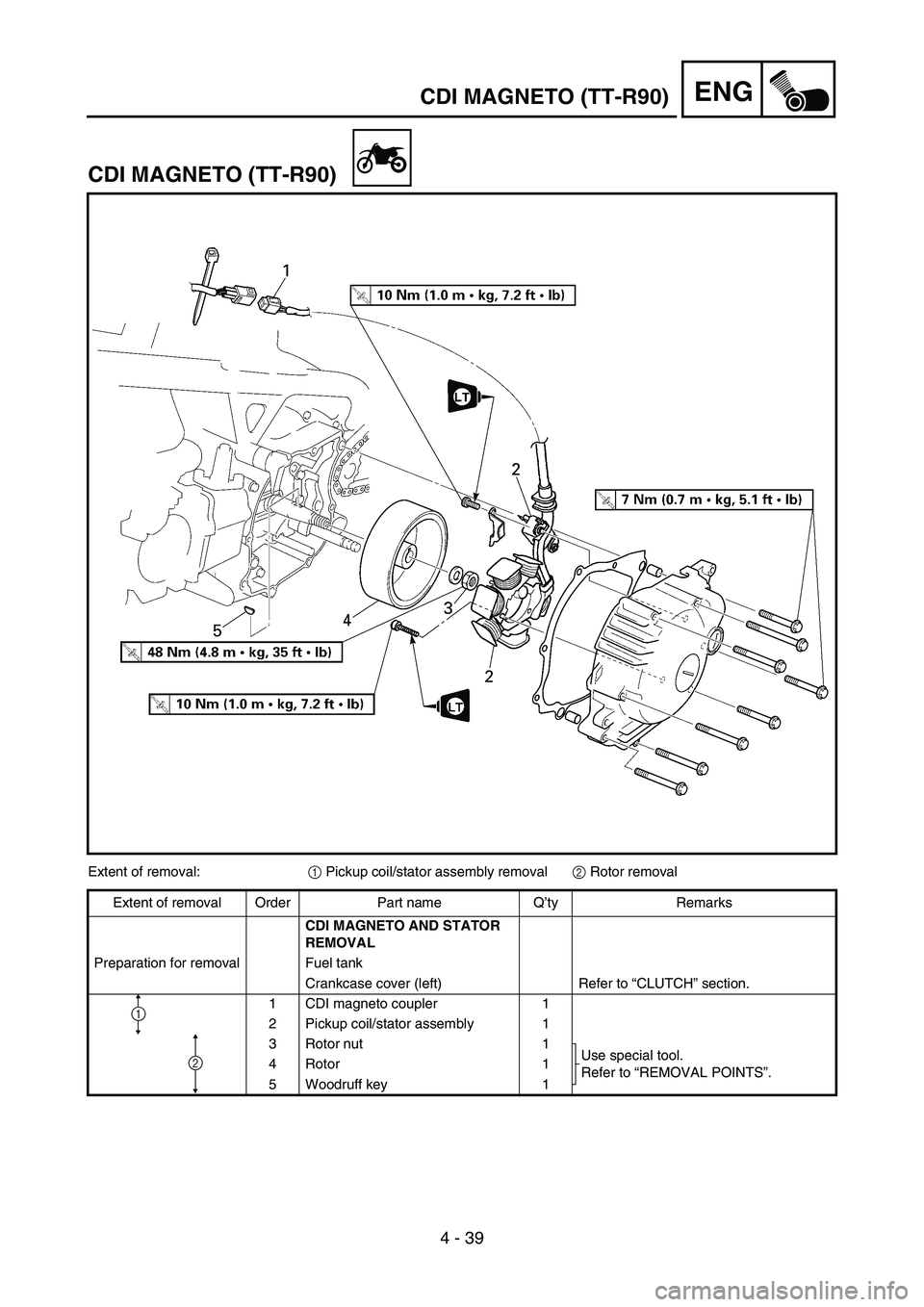
Extent of removal:
1 Pickup coil/stator assembly removal
2 Rotor removal
Extent of removal Order Part name Q’ty Remarks
CDI MAGNETO AND STATOR
REMOVAL
Preparation for removal Fuel tank
Crankcase cover (left) Refer to “CLUTCH” section.
1 CDI magneto coupler 1
2 Pickup coil/stator assembly 1
3 Rotor nut 1
Use special tool.
Refer to “REMOVAL POINTS”. 4 Rotor 1
5 Woodruff key 1
2
1
CDI MAGNETO (TT-R90)
Page 276 of 390
4 - 41
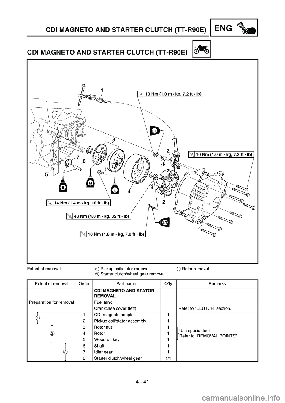
ENGCDI MAGNETO AND STARTER CLUTCH (TT-R90E)
CDI MAGNETO AND STARTER CLUTCH (TT-R90E)
Extent of removal:
1 Pickup coil/stator removal
2 Rotor removal
3 Starter clutch/wheel gear removal
Extent of removal Order Part name Q’ty Remarks
CDI MAGNETO AND STATOR
REMOVAL
Preparation for removal Fuel tank
Crankcase cover (left) Refer to “CLUTCH” section.
1 CDI magneto coupler 1
2 Pickup coil/stator assembly 1
3 Rotor nut 1
Use special tool.
Refer to “REMOVAL POINTS”. 4 Rotor 1
5 Woodruff key 1
6Shaft 1
7 Idler gear 1
8 Starter clutch/wheel gear 1/1
2
1
3
Page 284 of 390

4 - 45
ENGCRANKCASE AND CRANKSHAFT
CRANKCASE AND CRANKSHAFT
Extent of removal Order Part name Q’ty Remarks
CRANKCASE SEPARATION
AND CRANKSHAFT REMOVAL
Preparation for removal Seat, fuel tank and rear fender
Exhaust pipe
Air filter case
Carburetor Refer to “CARBURETOR” section.
Drain the engine oil Refer to “ENGINE OIL REPLACEMENT”
section in the CHAPTER 3.
Engine guard and drive sprocket
Engine assembly From the chassis.
Cylinder head Refer to “CYLINDER HEAD” section.
Cylinder and piston Refer to “CYLINDER AND PISTON” sec-
tion.
Clutch housing and clutch carrier Refer to “CLUTCH” section.
Kick axle assembly Refer to “KICK AXLE” section.
Page 342 of 390
–+ELEC
6 - 3
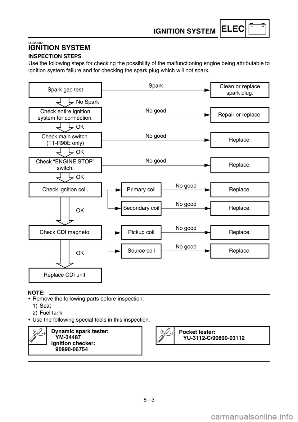
IGNITION SYSTEM
EC620000
IGNITION SYSTEM
INSPECTION STEPS
Use the following steps for checking the possibility of the malfunctioning engine being attributable to
ignition system failure and for checking the spark plug which will not spark.
NOTE:
Remove the following parts before inspection.
1) Seat
2) Fuel tank
Use the following special tools in this inspection.
Dynamic spark tester:
YM-34487
Ignition checker:
90890-06754Pocket tester:
YU-3112-C/90890-03112
Spark gap testClean or replace
spark plug.
Check entire ignition
system for connection.Repair or replace.
Check main switch.
(TT-R90E only)Replace.
Check “ENGINE STOP”
switch.Replace.
Check ignition coil. Primary coil Replace.
Secondary coil Replace.
Check CDI magneto. Pickup coil Replace.
Source coil Replace.
Replace CDI unit.
No Spark
OK
OK
OK
OK
OK
Spark
No good
No good
No good
No good
No good
No good
No good
Page 354 of 390
–+ELEC
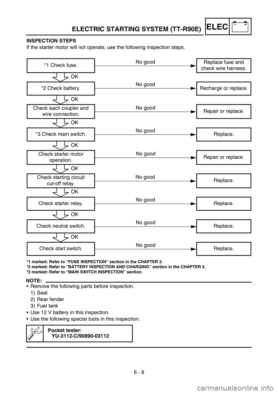
6 - 8 INSPECTION STEPS
If the starter motor will not operate, use the following inspection steps.
*1 marked: Refer to “FUSE INSPECTION” section in the CHAPTER 3.
*2 marked: Refer to “BATTERY INSPECTION AND CHARGING” section in the CHAPTER 3.
*3 marked: Refer to “MAIN SWITCH INSPECTION” section.
NOTE:
Remove the following parts before inspection.
1) Seat
2) Rear fender
3) Fuel tank
Use 12 V battery in this inspection.
Use the following special tools in this inspection.
Pocket tester:
YU-3112-C/90890-03112
*1 Check fuse.Replace fuse and
check wire harness.
*2 Check battery. Recharge or replace.
Check each coupler and
wire connection.Repair or replace.
*3 Check main switch. Replace.
Check starter motor
operation.Repair or replace.
Check starting circuit
cut-off relay.Replace.
Check starter relay. Replace.
Check neutral switch. Replace.
Check start switch. Replace.
OK
OK
OK
OK
OK
OK
OK
OK
No good
No good
No good
No good
No good
ELECTRIC STARTING SYSTEM (TT-R90E)
No good
No good
No good
No good
Page 370 of 390

–+ELEC
6 - 15
CHARGING SYSTEM (TT-R90E)
EC680000
CHARGING SYSTEM (TT-R90E)
EC681001
INSPECTION STEPS
If the battery is not charged, use the following inspection steps.
*1 marked: Refer to “FUSE INSPECTION” section in the CHAPTER 3.
*2 marked: Refer to “BATTERY INSPECTION AND CHARGING” section in the CHAPTER 3.
NOTE:
Remove the following parts before inspection.
1) Seat
2) Rear fender
3) Fuel tank
Use the following special tool in this inspection.
Pocket tester:
YU-3112-C/90890-03112Inductive tachometer:
YU-8036-B
Engine tachometer:
90890-03113
*1 Check fuse.Replace fuse and
check wire harness.
*2 Check battery. Recharge or replace.
Check each coupler and
wire connection.Repair or replace.
Check charging voltage.Charging system is
good.
Check CDI magneto. Lighting coil Replace.
Replace rectifier/regulator.
OK
OK
OK
No good
OK
No good
OK
No good
No good
No good
Page 376 of 390
–+ELEC
6 - 17
CARBURETOR HEATING SYSTEM
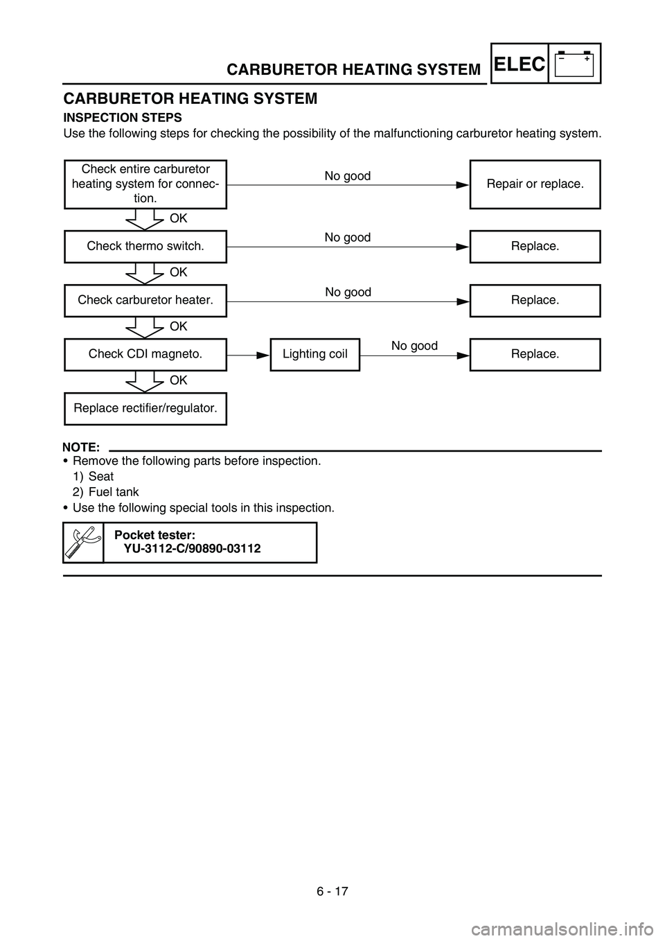
CARBURETOR HEATING SYSTEM
INSPECTION STEPS
Use the following steps for checking the possibility of the malfunctioning carburetor heating system.
NOTE:
Remove the following parts before inspection.
1) Seat
2) Fuel tank
Use the following special tools in this inspection.
Pocket tester:
YU-3112-C/90890-03112
Check entire carburetor
heating system for connec-
tion.Repair or replace.
Check thermo switch. Replace.
Check carburetor heater. Replace.
Check CDI magneto. Lighting coil Replace.
Replace rectifier/regulator.
OK
OK
OK
OK
No good
No good
No good
No good