warning YAMAHA VIKING 2014 Service Manual
[x] Cancel search | Manufacturer: YAMAHA, Model Year: 2014, Model line: VIKING, Model: YAMAHA VIKING 2014Pages: 180, PDF Size: 3.78 MB
Page 147 of 180
8-37
1
2
3
4
5
6
78
9
10
11
12
13
14
EVU00890Cable inspection and lubrication
WARNING
Damaged cables could restrict operation,
which may cause an accident or injury. In-
spect control cables frequently and re-
place damaged cables. Corrosion can
result when the outer covering of control
cables becomes damaged. Cables can
also become frayed or kinked.Lubricate the cable ends. If the cables do not
operate smoothly, ask a Yamaha dealer to re-
place them.
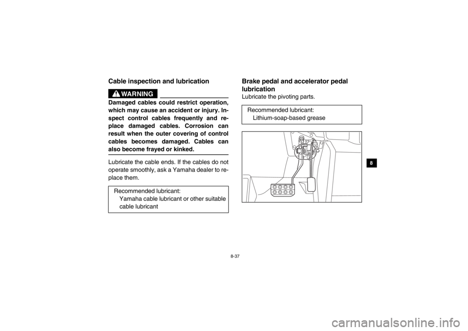
EVU00900Brake pedal and accelerator pedal
lubricationLubricate the pivoting parts.
Recommended lubricant: Yamaha cable lubricant or other suitable
cable lubricantRecommended lubricant: Lithium-soap-based grease
1XP7B_EE.book Page 37 Tuesday, February 4, 2014 3:40 PM
Page 150 of 180
8-40
8
9
10
11
12
13
14
Tire replacementAlways use the same size and type of tires
recommended in this owner’s manual. The
tires that came with your Yamaha Viking were
designed to match the performance capabili-
ties and to provide the best combination of
handling, braking, and comfort. It is best to re-
place all four tires at the same time. If that is
not possible, you must replace the tires in
pairs (front or rear) with tires of the same size
and type as the originals. Never replace just
one tire.
WARNING
Installing improper tires on your Yamaha
Viking can affect handling and stability.
This can cause a loss of control.
The tires listed below have been approved by
Yamaha Motor Manufacturing Corporation of America for this model.
Front tire:Size: 25 × 8-12NHS
Manufacturer/model:
MAXXIS/MU09
Rear tire: Size:
25 × 10-12NHS
Manufacturer/model: MAXXIS/MU10
1XP7B_EE.book Page 40 Tuesday, February 4, 2014 3:40 PM
Page 151 of 180
8-41
1
2
3
4
5
6
78
9
10
11
12
13
14
EVU00940Wheel installation1. Install the wheel and the nuts.
2. Lower the vehicle so that the wheel is onthe ground.
3. Tighten the wheel nuts in a crisscross pattern to the specified torque.
WARNING
Do not reverse the rims on your Yamaha
Viking to widen the track width. Installing
wheels improperly increases the risk of
wheel failure and accidents.
EVU00950BatteryThe battery is located under the hood. (See
page 8-7 for hood removal and installation
procedures.)
This model is equipped with a VRLA (Valve
Regulated Lead Acid) battery. There is no
need to check the electrolyte or to add distilled
water. However, the battery lead connections
need to be checked and, if necessary, tight-
ened.
Tightening torques: Front wheel nut: 75 Nm (7.5 m·kgf, 54 ft·lbf)
Rear wheel nut: 75 Nm (7.5 m·kgf, 54 ft·lbf)
1XP7B_EE.book Page 41 Tuesday, February 4, 2014 3:40 PM
Page 152 of 180
8-42
8
9
10
11
12
13
14
WARNING
Avoid battery contact with skin, eyes, or
clothing. Shield eyes when working near
batteries. Keep out of reach of children.
You could be poisoned or severely burned
by the sulfuric acid in battery electrolyte.
In case of accidental contact with battery
electrolyte:
EXTERNAL: Flush with water.
INTERNAL: Drink large quantities of water
or milk. Follow with milk of magnesia,
beaten egg, or vegetable oil. Get prompt
medical attention.
EYES: Flush with water for 15 minutes and
get prompt medical attention.
WARNING
Batteries may produce explosive gases.
Ventilate when charging or using in a
closed space. Keep batteries away from
sparks, flames, cigarettes, or other sourc-
es of ignition.
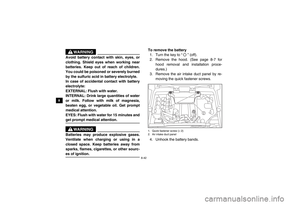
To remove the battery 1. Turn the key to “ ” (off).
2. Remove the hood. (See page 8-7 for hood removal and installation proce-
dures.)
3. Remove the air intake duct panel by re-
moving the quick fastener screws.1. Quick fastener screw ( × 2)
2. Air intake duct panel4. Unhook the battery bands.
2
1
1XP7B_EE.book Page 42 Tuesday, February 4, 2014 3:40 PM
Page 155 of 180
8-45
1
2
3
4
5
6
78
9
10
11
12
13
14
3. Hook the battery bands.
4. Install the air intake duct panel by install-ing the quick fastener screws.
5. Install the hood.
5B410022Jump-startingJump-starting the vehicle should be avoided.
The battery should be removed and charged
instead.
WARNING
To avoid battery explosion and/or serious
damage to the electrical system:●
Do not connect the negative lead of
the jumper cable to the negative termi-
nal of the battery.
●
Do not touch the positive lead of the
jumper cable to the negative lead.
●
Do not reverse the polarity of the
jumper cables when connecting to the
batteries.
1XP7B_EE.book Page 45 Tuesday, February 4, 2014 3:40 PM
Page 158 of 180
8-48
8
9
10
11
12
13
14
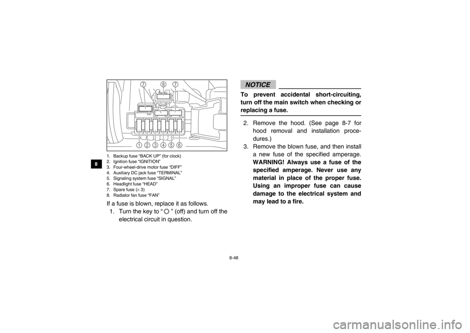
1. Backup fuse “BACK UP” (for clock)
2. Ignition fuse “IGNITION”
3. Four-wheel-drive motor fuse “DIFF”
4. Auxiliary DC jack fuse “TERMINAL”
5. Signaling system fuse “SIGNAL”
6. Headlight fuse “HEAD”
7. Spare fuse ( × 3)
8. Radiator fan fuse “FAN”If a fuse is blown, replace it as follows.
1. Turn the key to “ ” (off) and turn off the
electrical circuit in question.
NOTICETo prevent accidental short-circuiting,
turn off the main switch when checking or
replacing a fuse.2. Remove the hood. (See page 8-7 for hood removal and installation proce-
dures.)
3. Remove the blown fuse, and then install a new fuse of the specified amperage.
WARNING! Always use a fuse of the specified amperage. Never use any
material in place of the proper fuse.
Using an improper fuse can cause
damage to the electrical system and
may lead to a fire.
1
2
3
4
5
6
8
7
7
1XP7B_EE.book Page 48 Tuesday, February 4, 2014 3:40 PM
Page 165 of 180
8-55
1
2
3
4
5
6
78
9
10
11
12
13
14
EVU01010TroubleshootingAlthough Yamaha vehicles receive an inspec-
tion before shipment from the factory, trouble
may occur during operation. Any problem in
the fuel, compression, or ignition systems can
cause poor starting and loss of power. The
troubleshooting chart describes a quick, easy
procedure for making checks. If your vehicle
requires any repair, take it to a Yamaha deal-
er.
The skilled technicians at a Yamaha dealer-
ship have the tools, experience, and know-
how to properly service your vehicle. Use only
genuine Yamaha parts on your vehicle. Imita-
tion parts may look like Yamaha parts, but
they are often inferior. Consequently, they
have a shorter service life and can lead to ex-
pensive repair bills.
WARNING
When checking the fuel system, do not
smoke and make sure there are no open
flames or sparks in the area, including pi-
lot lights from water heaters or furnaces.
Gasoline or gasoline vapors can ignite or
explode, causing severe injury or property
damage.
1XP7B_EE.book Page 55 Tuesday, February 4, 2014 3:40 PM
Page 167 of 180
8-57
1
2
3
4
5
6
78
9
10
11
12
13
14
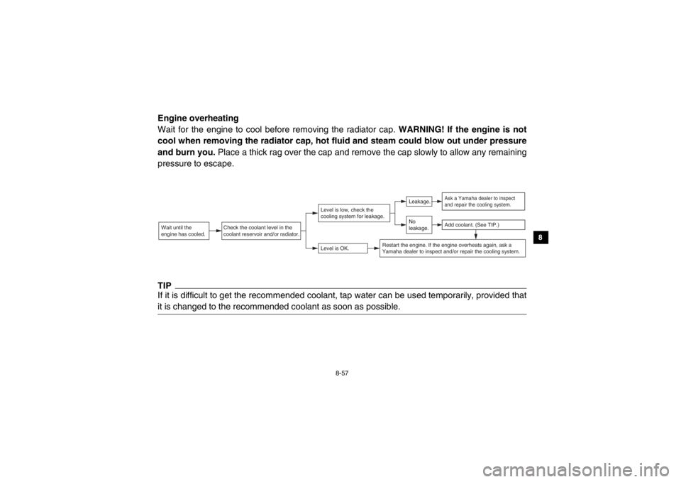
Engine overheating
Wait for the engine to cool before removing the radiator cap. WARNING! If the engine is not
cool when removing the radiator cap, hot fluid and steam could blow out under pressure
and burn you. Place a thick rag over the cap and remove the cap slowly to allow any remaining
pressure to escape.TIPIf it is difficult to get the recommended coolant, tap water can be used temporarily, provided that
it is changed to the recommended coolant as soon as possible.Wait until the
engine has cooled.
Check the coolant level in the
coolant reservoir and/or radiator.
Level is OK.Level is low, check the
cooling system for leakage.
No
leakage.Leakage.
Ask a Yamaha dealer to inspect
and repair the cooling system.Add coolant. (See TIP.)
Restart the engine. If the engine overheats again, ask a
Yamaha dealer to inspect and/or repair the cooling system.
1XP7B_EE.book Page 57 Tuesday, February 4, 2014 3:40 PM
Page 168 of 180

9-1
9
10
11
12
13
14
EVU01030
1-CLEANING AND STORAGE
CleaningFrequent, thorough cleaning of your vehicle
will not only enhance its appearance but will
improve its general performance and extend
the useful life of many components. 1. Before cleaning the vehicle:
a. Block off the end of the exhaust pipeto prevent water entry. A plastic bag
and strong rubber band may be used.
b. Make sure the spark plug and all filler caps are properly installed.
2. If the engine case is excessively greasy,
apply degreaser with a paint brush. Do
not apply degreaser to the wheel axles. 3. Rinse the dirt and degreaser off with a
garden hose. Use only enough pressure
to do the job. WARNING! Test the
brakes after washing. Apply the
brakes several times at slow speeds
to let friction dry out the linings. Wet
brakes may have reduced stopping
ability, increasing the chance of an ac-
cident. NOTICE: Excessive water
pressure may cause water seepage
and deterioration of wheel bearings,
brakes, transmission seals and elec-
trical devices. Many expensive repair
bills have resulted from improper
high-pressure detergent applications,
such as those available in coin-oper-
ated car washers.1XP7B_EE.book Page 1 Tuesday, February 4, 2014 3:40 PM
Page 175 of 180

10-5
1
2
3
4
5
6
7
8
910
11
12
13
14
Neutral indicator light:LED
Reverse indicator light: LED
Coolant temperature warning light:
LED
Engine trouble warning light: LED
Parking brake indicator light: LED
On-Command four-wheel-drive/differential gear lock indica-
tor: LCD
High-range indicator light:
LED
Low-range indicator light: LED
Differential gear lock indicator light: LED
EPS warning light:
LED
Helmet/Seat belt indicator light: 14 V, 0.85 W × 2Fuses:Main fuse:
40.0 A
Fuel injection system fuse: 10.0 A
EPS fuse: 40.0 A
Headlight fuse:
15.0 A Signaling system fuse:
10.0 A
Ignition fuse: 10.0 A
Auxiliary DC jack fuse:
10.0 A
Backup fuse: 10.0 A
Four-wheel-drive motor fuse: 10.0 A
Radiator fan fuse:
25.0 A
For Europe only
The figures quoted are emission levels and
are not necessarily safe working levels. Whilst
there is a correlation between the emission
and exposure levels, this cannot be used reli-
ably to determine whether or not further pre-
cautions are required.
Factors that influence the actual level of expo-
sure of work-force include the characteristics
of the work room, the other sources of noise,
etc. i.e. the number of machines and other ad-
jacent processes, and the length of time for
which an operator is exposed to the noise.
Also the permissible exposure level can vary
1XP7B_EE.book Page 5 Tuesday, February 4, 2014 3:40 PM