YAMAHA VMAX 2001 Owner's Manual
Manufacturer: YAMAHA, Model Year: 2001, Model line: VMAX, Model: YAMAHA VMAX 2001Pages: 110, PDF Size: 11.88 MB
Page 21 of 110
INSTRUMENT AND CONTROL FUNCTIONS
3-6
3
EAU00157
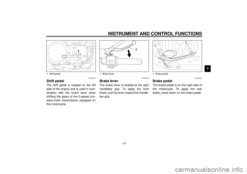
Shift pedal The shift pedal is located on the left
side of the engine and is used in com-
bination with the clutch lever when
shifting the gears of the 5-speed con-
stant-mesh transmission equipped on
this motorcycle.
EAU00158
Brake lever The brake lever is located at the right
handlebar grip. To apply the front
brake, pull the lever toward the handle-
bar grip.
EAU00162
Brake pedal The brake pedal is on the right side of
the motorcycle. To apply the rear
brake, press down on the brake pedal.
1. Shift pedal
1. Brake lever
1. Brake pedal
E_3lr.book Page 6 Wednesday, November 22, 2000 4:10 PM
Page 22 of 110
INSTRUMENT AND CONTROL FUNCTIONS
3-7
3
EAU01654
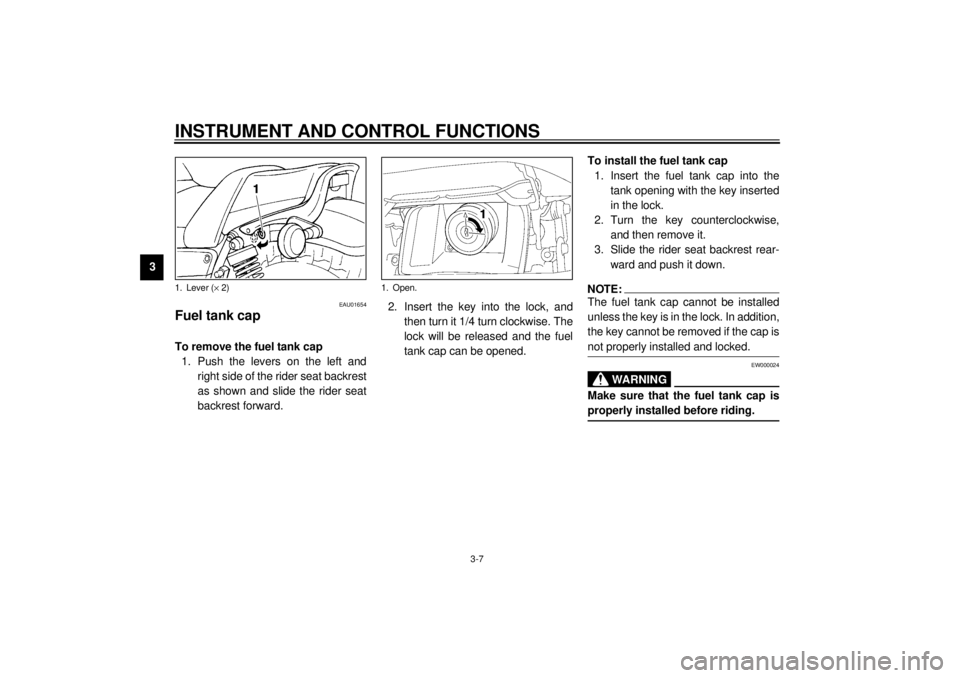
Fuel tank cap To remove the fuel tank cap
1. Push the levers on the left and
right side of the rider seat backrest
as shown and slide the rider seat
backrest forward.2. Insert the key into the lock, and
then turn it 1/4 turn clockwise. The
lock will be released and the fuel
tank cap can be opened.To install the fuel tank cap
1. Insert the fuel tank cap into the
tank opening with the key inserted
in the lock.
2. Turn the key counterclockwise,
and then remove it.
3. Slide the rider seat backrest rear-
ward and push it down.
NOTE:@ The fuel tank cap cannot be installed
unless the key is in the lock. In addition,
the key cannot be removed if the cap is
not properly installed and locked. @
EW000024
WARNING
@ Make sure that the fuel tank cap is
properly installed before riding. @
1. Lever (´ 2)
1. Open.
E_3lr.book Page 7 Wednesday, November 22, 2000 4:10 PM
Page 23 of 110
INSTRUMENT AND CONTROL FUNCTIONS
3-8
3
EAU01183
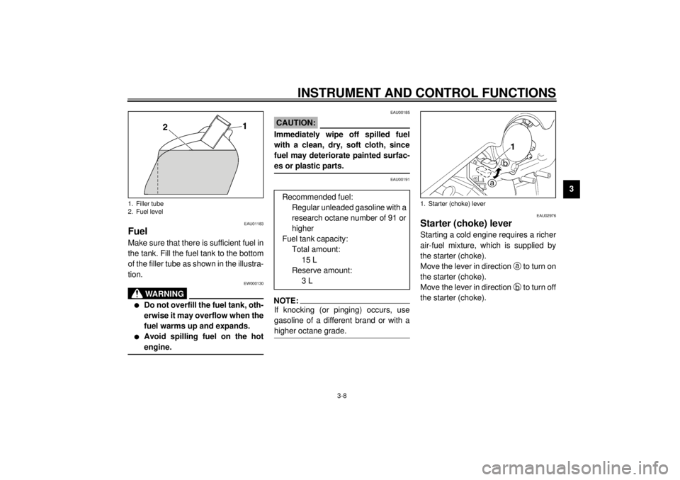
Fuel Make sure that there is sufficient fuel in
the tank. Fill the fuel tank to the bottom
of the filler tube as shown in the illustra-
tion.
EW000130
WARNING
@ l
Do not overfill the fuel tank, oth-
erwise it may overflow when the
fuel warms up and expands.
l
Avoid spilling fuel on the hot
engine.
@
EAU00185
CAUTION:@ Immediately wipe off spilled fuel
with a clean, dry, soft cloth, since
fuel may deteriorate painted surfac-
es or plastic parts. @
EAU00191
NOTE:@ If knocking (or pinging) occurs, use
gasoline of a different brand or with a
higher octane grade. @
EAU02976
Starter (choke) lever Starting a cold engine requires a richer
air-fuel mixture, which is supplied by
the starter (choke).
Move the lever in direction
a to turn on
the starter (choke).
Move the lever in direction
b to turn off
the starter (choke).
1. Filler tube
2. Fuel level
Recommended fuel:
Regular unleaded gasoline with a
research octane number of 91 or
higher
Fuel tank capacity:
Total amount:
15 L
Reserve amount:
3 L
1. Starter (choke) lever
E_3lr.book Page 8 Wednesday, November 22, 2000 4:10 PM
Page 24 of 110
INSTRUMENT AND CONTROL FUNCTIONS
3-9
3
EAU03342
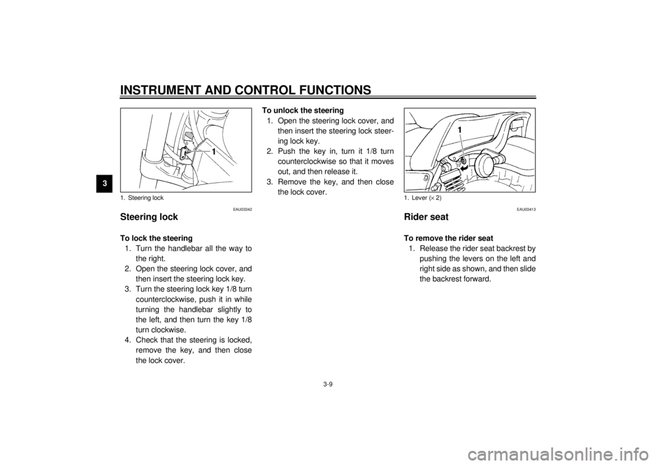
Steering lock To lock the steering
1. Turn the handlebar all the way to
the right.
2. Open the steering lock cover, and
then insert the steering lock key.
3. Turn the steering lock key 1/8 turn
counterclockwise, push it in while
turning the handlebar slightly to
the left, and then turn the key 1/8
turn clockwise.
4. Check that the steering is locked,
remove the key, and then close
the lock cover.To unlock the steering
1. Open the steering lock cover, and
then insert the steering lock steer-
ing lock key.
2. Push the key in, turn it 1/8 turn
counterclockwise so that it moves
out, and then release it.
3. Remove the key, and then close
the lock cover.
EAU03413
Rider seat To remove the rider seat
1. Release the rider seat backrest by
pushing the levers on the left and
right side as shown, and then slide
the backrest forward.
1. Steering lock
1. Lever (´ 2)
E_3lr.book Page 9 Wednesday, November 22, 2000 4:10 PM
Page 25 of 110
INSTRUMENT AND CONTROL FUNCTIONS
3-10
3
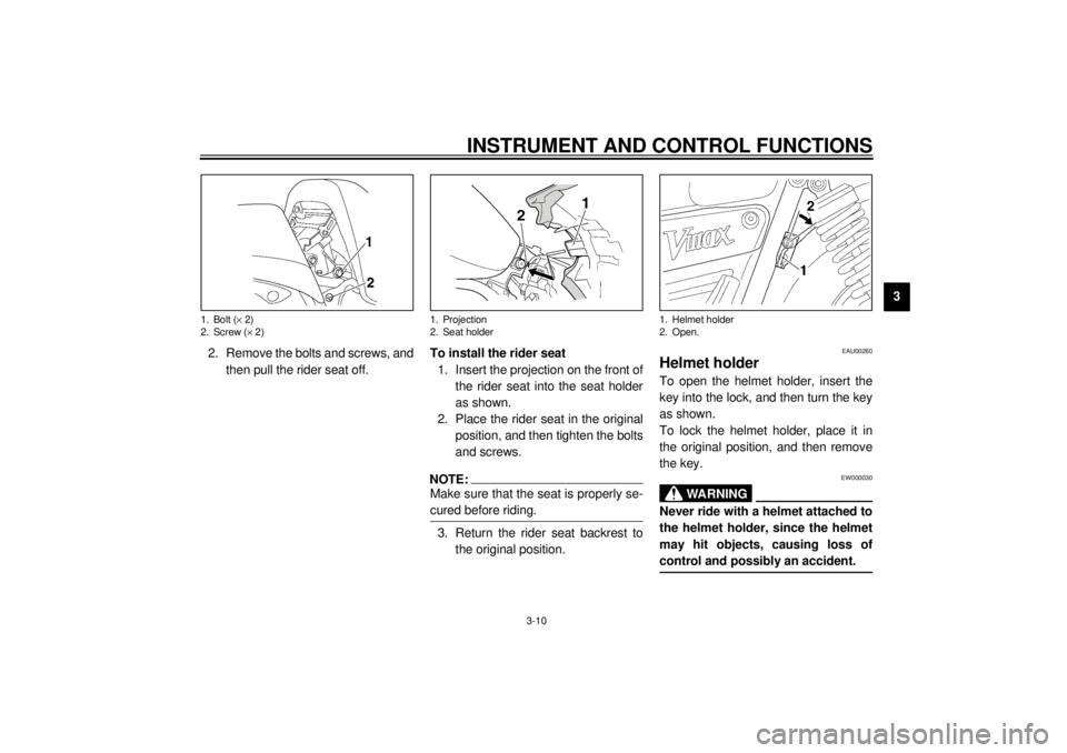
2. Remove the bolts and screws, and
then pull the rider seat off.To install the rider seat
1. Insert the projection on the front of
the rider seat into the seat holder
as shown.
2. Place the rider seat in the original
position, and then tighten the bolts
and screws.
NOTE:@ Make sure that the seat is properly se-
cured before riding. @3. Return the rider seat backrest to
the original position.
EAU00260
Helmet holder To open the helmet holder, insert the
key into the lock, and then turn the key
as shown.
To lock the helmet holder, place it in
the original position, and then remove
the key.
EW000030
WARNING
@ Never ride with a helmet attached to
the helmet holder, since the helmet
may hit objects, causing loss of
control and possibly an accident. @
1. Bolt (´ 2)
2. Screw (´ 2)
1. Projection
2. Seat holder
1. Helmet holder
2. Open.
E_3lr.book Page 10 Wednesday, November 22, 2000 4:10 PM
Page 26 of 110
INSTRUMENT AND CONTROL FUNCTIONS
3-11
3
EAU03414
Adjusting the front fork This front fork is equipped with air
valves for adjusting the spring rate.
EW000035
WARNING
@ Always adjust both fork legs equal-
ly, otherwise poor handling and loss
of stability may result. @
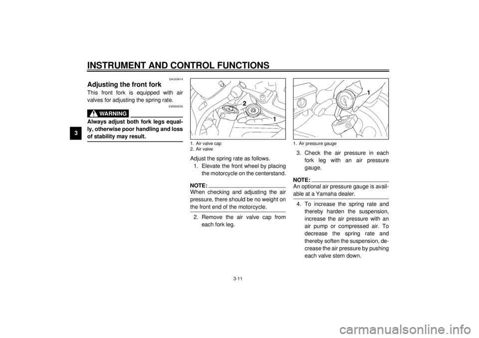
Adjust the spring rate as follows.
1. Elevate the front wheel by placing
the motorcycle on the centerstand.NOTE:@ When checking and adjusting the air
pressure, there should be no weight on
the front end of the motorcycle. @2. Remove the air valve cap from
each fork leg.3. Check the air pressure in each
fork leg with an air pressure
gauge.
NOTE:@ An optional air pressure gauge is avail-
able at a Yamaha dealer. @4. To increase the spring rate and
thereby harden the suspension,
increase the air pressure with an
air pump or compressed air. To
decrease the spring rate and
thereby soften the suspension, de-
crease the air pressure by pushing
each valve stem down.
1. Air valve cap
2. Air valve
1. Air pressure gauge
E_3lr.book Page 11 Wednesday, November 22, 2000 4:10 PM
Page 27 of 110
INSTRUMENT AND CONTROL FUNCTIONS
3-12
3
EC000012
CAUTION:@ Never exceed the maximum air pres-
sure, otherwise the front fork oil
seals may become damaged. @
EWA00037
WARNING
@ There must be no difference in air
pressure between the left and right
fork legs, otherwise poor handling
and loss of stability may result. @5. Securely install the air valve caps.
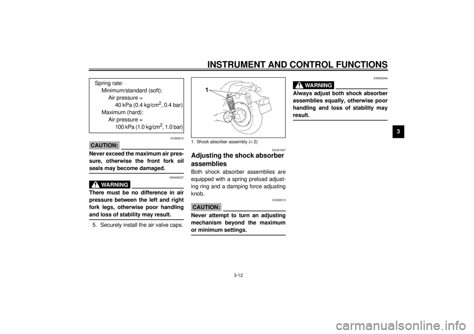
EAU01657
Adjusting the shock absorber
assemblies Both shock absorber assemblies are
equipped with a spring preload adjust-
ing ring and a damping force adjusting
knob.
EC000015
CAUTION:@ Never attempt to turn an adjusting
mechanism beyond the maximum
or minimum settings. @
EW000040
WARNING
@ Always adjust both shock absorber
assemblies equally, otherwise poor
handling and loss of stability may
result. @
Spring rate:
Minimum/standard (soft):
Air pressure =
40 kPa (0.4 kg/cm
2, 0.4 bar)
Maximum (hard):
Air pressure =
100 kPa (1.0 kg/cm2, 1.0 bar)
1. Shock absorber assembly (´ 2)
E_3lr.book Page 12 Wednesday, November 22, 2000 4:10 PM
Page 28 of 110
INSTRUMENT AND CONTROL FUNCTIONS
3-13
3
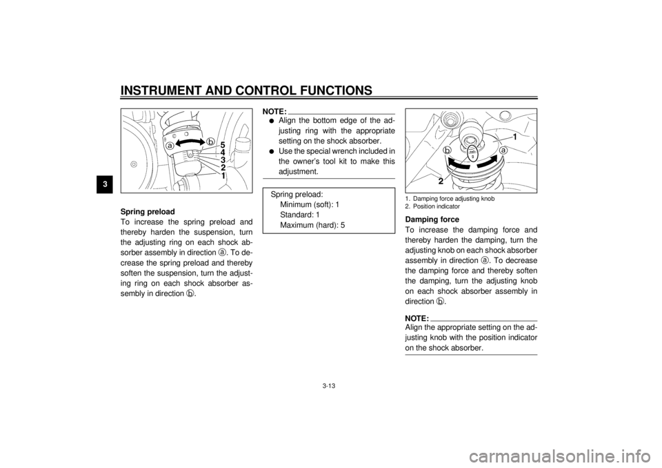
Spring preload
To increase the spring preload and
thereby harden the suspension, turn
the adjusting ring on each shock ab-
sorber assembly in direction
a. To de-
crease the spring preload and thereby
soften the suspension, turn the adjust-
ing ring on each shock absorber as-
sembly in direction
b.
NOTE:@ l
Align the bottom edge of the ad-
justing ring with the appropriate
setting on the shock absorber.
l
Use the special wrench included in
the owner’s tool kit to make this
adjustment.
@
Damping force
To increase the damping force and
thereby harden the damping, turn the
adjusting knob on each shock absorber
assembly in direction
a. To decrease
the damping force and thereby soften
the damping, turn the adjusting knob
on each shock absorber assembly in
direction
b.NOTE:@ Align the appropriate setting on the ad-
justing knob with the position indicator
on the shock absorber. @
Spring preload:
Minimum (soft): 1
Standard: 1
Maximum (hard): 5
1. Damping force adjusting knob
2. Position indicator
E_3lr.book Page 13 Wednesday, November 22, 2000 4:10 PM
Page 29 of 110

INSTRUMENT AND CONTROL FUNCTIONS
3-14
3 Damping force:
Minimum (soft): 1
Standard: 1
Maximum (hard): 4
E_3lr.book Page 14 Wednesday, November 22, 2000 4:10 PM
Page 30 of 110

INSTRUMENT AND CONTROL FUNCTIONS
3-15
3
EAU01658
Matching the front and rear suspension settings Use this table as a guide to match the suspension and damping adjustments of the front fork and shock absorber assembly
according to various load conditions.CI-06E
EC000015CAUTION:@ Never attempt to turn an adjusting mechanism beyond the maximum or minimum settings. @
Load condition Front fork adjustment Shock absorber assembly adjustment
Spring preload (air pressure) Spring preload Damping force
Rider only40–60 kPa
0.4–0.6 kg/cm
2
0.4–0.6 bar1–2 1–2
With passenger or with
accessories and equipment40–100 kPa
0.4–1.0 kg/cm
2
0.4–1.0 bar3–5 2–4
With passenger,
accessories and equipment40–100 kPa
0.4–1.0 kg/cm
2
0.4–1.0 bar54
E_3lr.book Page 15 Wednesday, November 22, 2000 4:10 PM