YAMAHA VX110 2005 Service Manual
VX110 2005
YAMAHA
YAMAHA
https://www.carmanualsonline.info/img/51/57494/w960_57494-0.png
YAMAHA VX110 2005 Service Manual
Trending: octane, fuel consumption, boot, wheel, maintenance, buttons, stop start
Page 311 of 347
8-18
E
HULL
HOODHOSES
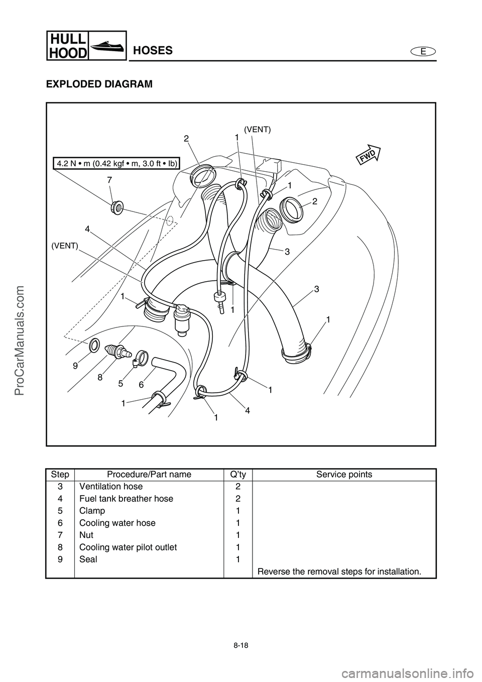
EXPLODED DIAGRAM
Step Procedure/Part name Q’ty Service points
3 Ventilation hose 2
4 Fuel tank breather hose 2
5Clamp 1
6 Cooling water hose 1
7Nut 1
8 Cooling water pilot outlet 1
9 Seal 1
Reverse the removal steps for installation.
4
1 7
9
8
5
6
1
11
3
1
1
2
3
21
1
4
4.2 N • m (0.42 kgf • m, 3.0 ft • Ib)
(VENT)
(VENT)
FWD
ProCarManuals.com
Page 312 of 347
8-19
E
HULL
HOOD
SERVICE POINTS
Cooling water pilot outlet installation
1. Install:
Cooling water pilot outlet 1
Seal 2
Nut 3
NOTE:
When installing the cooling water pilot outlet,
face the discharge hole toward the stern and
downward at a 30° angle from the horizontal
line as shown in the illustration.
Tighten the nut while holding the cooling
water pilot outlet in place.
30˚
FWD3
12
Grommet installation
1. Install:
Ventilation hose 1
Grommet 2
NOTE:
Install the grommet on the ventilation hose,
making sure that the end of the hose protrudes
the specified length a from the groove around
the outside of the grommet as shown in the
illustration.
Specified length a:
30–40 mm (1.18–1.57 in)
1
2
a
Ventilation hose assembly installation
1. Install:
Ventilation hose assembly
NOTE:
When installing the ventilation hose assembly,
make sure that the grommet is properly seated
in the hole in the inner hull as shown in the
illustration.
HOSES
ProCarManuals.com
Page 313 of 347
8-20
E
HULL
HOODSTEERING COLUMN
STEERING COLUMN
EXPLODED DIAGRAM
REMOVAL AND INSTALLATION CHART
Step Procedure/Part name Q’ty Service points
STEERING COLUMN REMOVAL
Follow the left “Step” for removal.
Engine hatch cover Refer to “ENGINE HATCH COVER”.
Steering cable end Refer to “REMOTE CONTROL CABLES
AND SPEED SENSOR LEAD”.
1Bolt 1
2 Steering arm 1
3 Joint ball 1
4Bolt 4
5 Steering column assembly 1
Reverse the removal steps for installation.
5
4
2
3 1
6.9 N • m (0.69 kgf m, 5.0 ft Ib)
8 × 30 mm
17 N m (1.7 kgf m, 12 ft Ib)
LT
572
LT
LT
242
LT
8 × 18 mm
20 N m (2.0 kgf m, 14 ft Ib)
ProCarManuals.com
Page 314 of 347
8-21
E
HULL
HOODSTEERING COLUMN
EXPLODED DIAGRAM
REMOVAL AND INSTALLATION CHART
Step Procedure/Part name Q’ty Service points
STEERING COLUMN
DISASSEMBLYFollow the left “Step” for disassembly.
1 Steering column 1
2 Seal rubber 1
3Bolt 4
4 Steering sensor 1
5Bolt 3
6 Spacer 1
7Buzzer 1
8 Steering housing assembly 1
Reverse the disassembly steps for
assembly.
6
LT
572
LT
LT
572
LT
3
4 1
8
27 5
7
8 × 25 mm
16 N • m (1.6 kgf • m, 12 ft • Ib)
ProCarManuals.com
Page 315 of 347
8-22
E
HULL
HOODSTEERING COLUMN
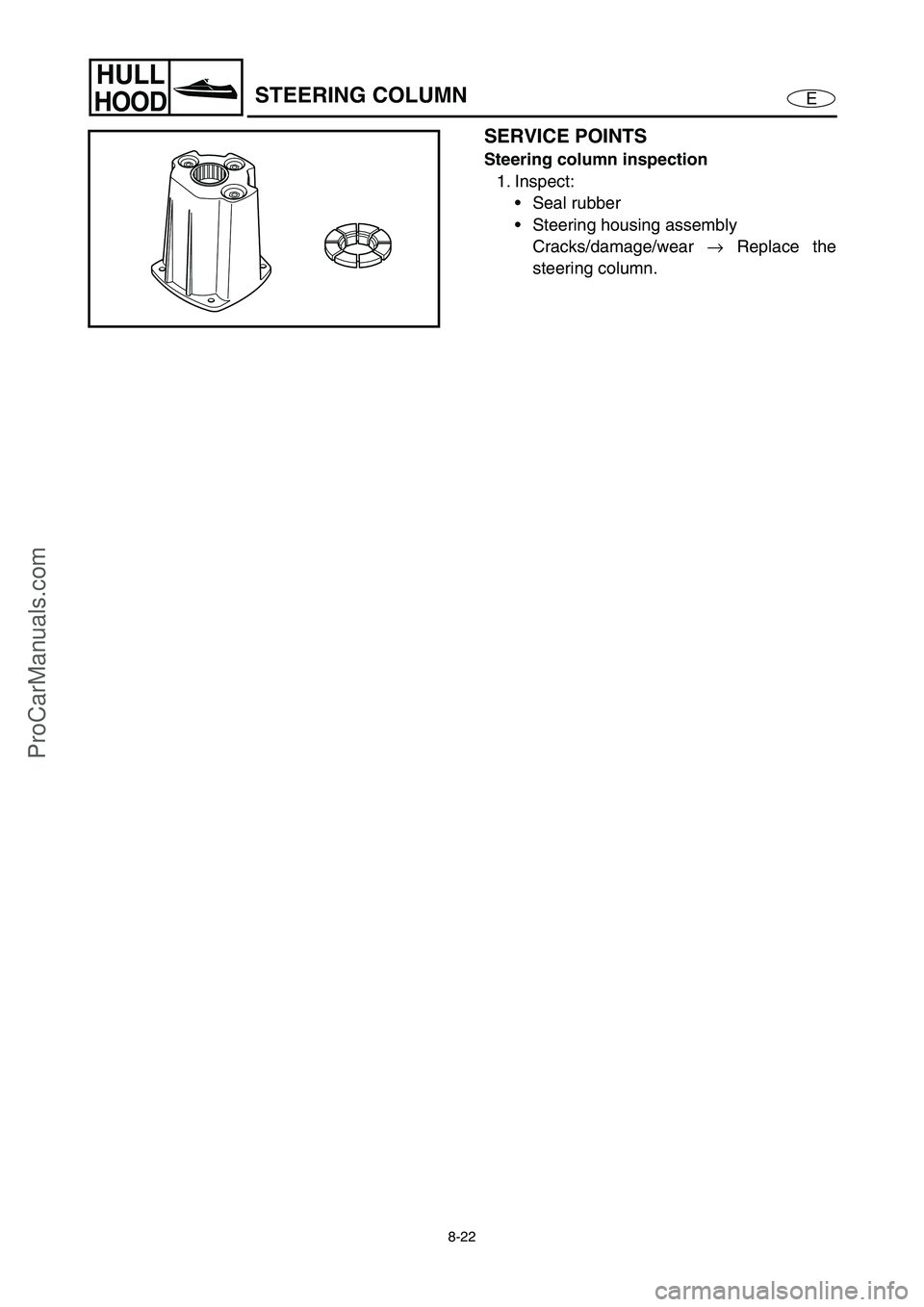
SERVICE POINTS
Steering column inspection
1. Inspect:
Seal rubber
Steering housing assembly
Cracks/damage/wear →
Replace the
steering column.
ProCarManuals.com
Page 316 of 347
8-23
E
HULL
HOOD
REMOTE CONTROL CABLES AND
SPEED SENSOR LEAD
REMOTE CONTROL CABLES AND SPEED SENSOR LEAD
EXPLODED DIAGRAM
REMOVAL AND INSTALLATION CHART
Step Procedure/Part name Q’ty Service points
REMOTE CONTROL CABLES
AND SPEED SENSOR LEAD
REMOVALFollow the left “Step” for removal.
Service lid 1 Refer to “FRONT HOOD”.
Seat assembly Refer to “SEAT AND HAND GRIP”.
Engine hatch cover Refer to “ENGINE HATCH COVER”.
Shift lever Refer to “SHIFT LEVER (DELUXE MODEL
ONLY)”.
1 Steering cable end 1
2Bolt 1
3Bracket 1
ProCarManuals.com
Page 317 of 347
8-24
E
HULL
HOOD
REMOTE CONTROL CABLES AND
SPEED SENSOR LEAD
EXPLODED DIAGRAM
Step Procedure/Part name Q’ty Service points
4Nut 1
5 Steering cable 1
6 Seal 1
7 Speed sensor coupler 1
8Nut 1
9Cap 1
10 Screw 4
11 Speed sensor 1
12 Bolt 2 Deluxe model only
13 Shift cable holder 1 Deluxe model only
ProCarManuals.com
Page 318 of 347
8-25
E
HULL
HOOD
REMOTE CONTROL CABLES AND
SPEED SENSOR LEAD
EXPLODED DIAGRAM
Step Procedure/Part name Q’ty Service points
14 Shift cable end 1 Deluxe model only
15 Grommet 1 Deluxe model only
16 Nut 1 Deluxe model only
17 Shift cable 1 Deluxe model only
18 Seal 1 Deluxe model only
Reverse the removal steps for installation.
ProCarManuals.com
Page 319 of 347
8-26
E
HULL
HOOD
REMOTE CONTROL CABLES AND
SPEED SENSOR LEAD
SERVICE POINTS
WARNING
When routing the cables, do not grasp the
cable by the outer crimped sheath or steel
end. This could deform or loosen the cable
end due to extreme angles and or pressure.
Always hold the cables by the outer cover
below the crimp.
If a cable becomes damaged replace it.
Never attempt to repair a damaged cable.
Remote control cables inspection
1. Inspect:
Steering cable
Shift cable (Deluxe model only)
Frays/kinks/rough movement →
Replace.
Steering cable (jet pump end) installation
1. Install:
Steering cable
WARNING
The steering cable must be screwed in at
least 8 mm (0.31 in).
Steering cable set length
a
(jet pump end):
14.5 mm (0.57 in)
Steering cable stopper installation
1. Install:
Steering cable stopper
WARNING
Be sure to the steering cable stopper into
the groove in the outer cable as shown in
the illustration.
ProCarManuals.com
Page 320 of 347
8-27
E
HULL
HOOD
REMOTE CONTROL CABLES AND
SPEED SENSOR LEAD
Shift cable (jet pump end) installation
(Deluxe model only)
1. Install:
Shift cable (jet pump end)
WARNING
The shift cable must be screwed in more
than 8 mm (0.31 in).
Shift cable set length
a
(jet pump end):
13.6 mm (0.54 in)
Shift cable (shift lever end) installation
(Deluxe model only)
1. Install:
Shift cable (shift lever end)
NOTE:
Install the shift cable 1
before securing the
shift lever assembly 2
to the deck.12
Remote control cables adjustment
Refer to “CONTROL SYSTEM” in Chap-
ter 3.
ProCarManuals.com
Trending: charging, fuel tank capacity, octane, fuse diagram, oil pressure, lock, transmission


