YAMAHA VX110 2005 Service Manual
Manufacturer: YAMAHA, Model Year: 2005, Model line: VX110, Model: YAMAHA VX110 2005Pages: 347, PDF Size: 14.17 MB
Page 291 of 347

ProCarManuals.com
Page 292 of 347
E
HULL
HOOD
CHAPTER 8
HULL AND HOOD
HANDLEBAR .................................................................................................. 8-1
EXPLODED DIAGRAM ............................................................................. 8-1
REMOVAL AND INSTALLATION CHART ................................................ 8-1
SERVICE POINTS .................................................................................... 8-6
Handlebar inspection .......................................................................... 8-6
Handlebar switch inspection ............................................................... 8-6
Handlebar assembly installation ......................................................... 8-6
FRONT HOOD ................................................................................................. 8-8
EXPLODED DIAGRAM ............................................................................. 8-8
REMOVAL AND INSTALLATION CHART ................................................ 8-8
SERVICE POINTS .................................................................................. 8-10
Rivet Installation ................................................................................ 8-10
ENGINE HATCH COVER .............................................................................. 8-11
EXPLODED DIAGRAM ........................................................................... 8-11
REMOVAL AND INSTALLATION CHART .............................................. 8-11
SERVICE POINTS .................................................................................. 8-13
Damper stopper inspection (Deluxe model only) .............................. 8-13
EXPLODED DIAGRAM ........................................................................... 8-14
REMOVAL AND INSTALLATION CHART .............................................. 8-14
SERVICE POINTS .................................................................................. 8-15
Glove compartment assembly installation......................................... 8-15
SHIFT LEVER (DELUXE MODEL ONLY) ..................................................... 8-16
EXPLODED DIAGRAM ........................................................................... 8-16
REMOVAL AND INSTALLATION CHART .............................................. 8-16
HOSES .......................................................................................................... 8-17
EXPLODED DIAGRAM ........................................................................... 8-17
REMOVAL AND INSTALLATION CHART .............................................. 8-17
SERVICE POINTS .................................................................................. 8-19
Cooling water pilot outlet installation ................................................. 8-19
Grommet installation ......................................................................... 8-19
Ventilation hose assembly installation .............................................. 8-19
STEERING COLUMN .................................................................................... 8-20
EXPLODED DIAGRAM ........................................................................... 8-20
REMOVAL AND INSTALLATION CHART .............................................. 8-20
SERVICE POINTS .................................................................................. 8-22
Steering column inspection ............................................................... 8-22
ProCarManuals.com
Page 293 of 347

E
HULL
HOOD
1
2
3
4
5
6
7
8
9
REMOTE CONTROL CABLES AND SPEED SENSOR LEAD .................... 8-23
EXPLODED DIAGRAM ........................................................................... 8-23
REMOVAL AND INSTALLATION CHART .............................................. 8-23
SERVICE POINTS .................................................................................. 8-26
Remote control cables inspection ..................................................... 8-26
Steering cable (jet pump end) installation ......................................... 8-26
Steering cable stopper installation .................................................... 8-26
Shift cable (jet pump end) installation (Deluxe model only) .............. 8-27
Shift cable (shift lever end) installation (Deluxe model only)............. 8-27
Remote control cables adjustment .................................................... 8-27
SEAT AND HAND GRIP................................................................................ 8-28
EXPLODED DIAGRAM ........................................................................... 8-28
REMOVAL AND INSTALLATION CHART .............................................. 8-28
SERVICE POINTS .................................................................................. 8-30
Seat lock assembly inspection .......................................................... 8-30
EXHAUST SYSTEM ...................................................................................... 8-31
EXPLODED DIAGRAM ........................................................................... 8-31
REMOVAL AND INSTALLATION CHART .............................................. 8-31
SERVICE POINTS .................................................................................. 8-34
Exhaust system inspection................................................................ 8-34
Exhaust component parts sub-assembly .......................................... 8-34
Exhaust system installation ............................................................... 8-35
DECK AND HULL.......................................................................................... 8-36
EXPLODED DIAGRAM ........................................................................... 8-36
REMOVAL AND INSTALLATION CHART .............................................. 8-36
ENGINE MOUNT ........................................................................................... 8-38
EXPLODED DIAGRAM ........................................................................... 8-38
REMOVAL AND INSTALLATION CHART .............................................. 8-38
ProCarManuals.com
Page 294 of 347
8-1
E
HULL
HOODHANDLEBAR
HANDLEBAR
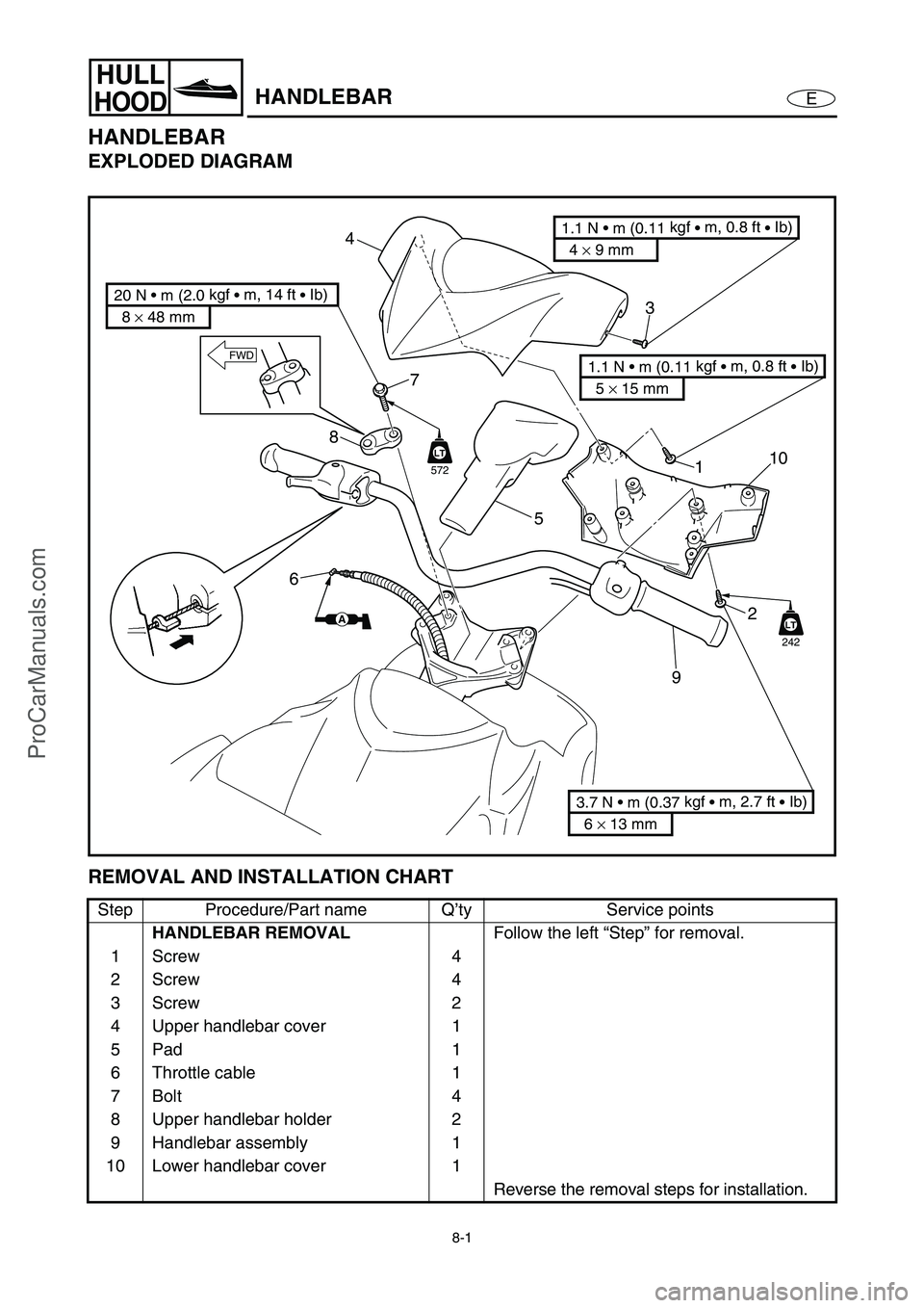
EXPLODED DIAGRAM
REMOVAL AND INSTALLATION CHART
Step Procedure/Part name Q’ty Service points
HANDLEBAR REMOVAL
Follow the left “Step” for removal.
1Screw 4
2Screw 4
3Screw 2
4 Upper handlebar cover 1
5Pad 1
6 Throttle cable 1
7Bolt 4
8 Upper handlebar holder 2
9 Handlebar assembly 1
10 Lower handlebar cover 1
Reverse the removal steps for installation.
LT
242
8 × 48 mm
20 N • m (2.0 kgf
• m, 14 ft
• Ib)
6 × 13 mm
3.7 N • m (0.37 kgf
• m, 2.7 ft
• Ib)
4 × 9 mm
1.1 N • m (0.11 kgf
• m, 0.8 ft
• Ib)
5 × 15 mm
1.1 N • m (0.11 kgf
• m, 0.8 ft
• Ib)
87
1
2
910
5
4
3
6
FWD
AA
LT
572
ProCarManuals.com
Page 295 of 347

8-2
E
HULL
HOODHANDLEBAR
EXPLODED DIAGRAM
REMOVAL AND INSTALLATION CHART
Step Procedure/Part name Q’ty Service points
HANDLEBAR REMOVAL
Follow the left “Step” for removal.
1 Handlebar switch coupler 2
2 Plastic tie 1
NOTE:
Fasten the buzzer lead, steering sensor
lead, start switch lead, engine shut-off
switch lead, and multifunction meter lead
with a plastic tie.
3 Corrugated tube 1
4 Grommet 1
4 5
3
4
3
7
2
FWD
6
11
6
ProCarManuals.com
Page 296 of 347
8-3
E
HULL
HOODHANDLEBAR
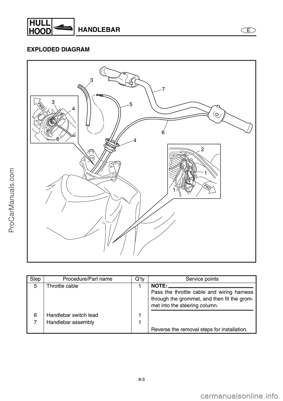
EXPLODED DIAGRAM
Step Procedure/Part name Q’ty Service points
5 Throttle cable 1
NOTE:
Pass the throttle cable and wiring harness
through the grommet, and then fit the grom-
met into the steering column.
6 Handlebar switch lead 1
7 Handlebar assembly 1
Reverse the removal steps for installation.
4 5
3
4
3
7
2
FWD
6
11
6
ProCarManuals.com
Page 297 of 347

8-4
E
HULL
HOODHANDLEBAR
EXPLODED DIAGRAM
REMOVAL AND INSTALLATION CHART
Step Procedure/Part name Q’ty Service points
HANDLEBAR DISASSEMBLY
Follow the left “Step” for disassembly.
1Bolt 2
2 Grip end 2
3Screw 2
NOTE:
Tighten the screw from the engine stop
switch side.
4 Handlebar switch assembly 1
5Screw 2
ProCarManuals.com
Page 298 of 347
8-5
E
HULL
HOODHANDLEBAR
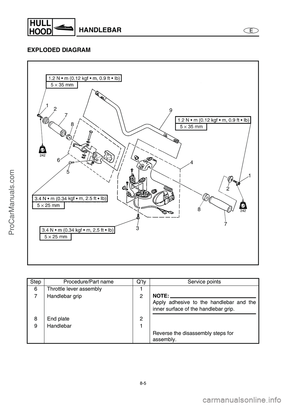
EXPLODED DIAGRAM
Step Procedure/Part name Q’ty Service points
6 Throttle lever assembly 1
7 Handlebar grip 2
NOTE:
Apply adhesive to the handlebar and the
inner surface of the handlebar grip.
8 End plate 2
9 Handlebar 1
Reverse the disassembly steps for
assembly.
ProCarManuals.com
Page 299 of 347
8-6
E
HULL
HOODHANDLEBAR
SERVICE POINTS
Handlebar inspection
1. Inspect:
Handlebar
Bends/cracks/damage →
Replace.
Handlebar switch inspection
Refer to “STARTING SYSTEM” in
Chapter 7.
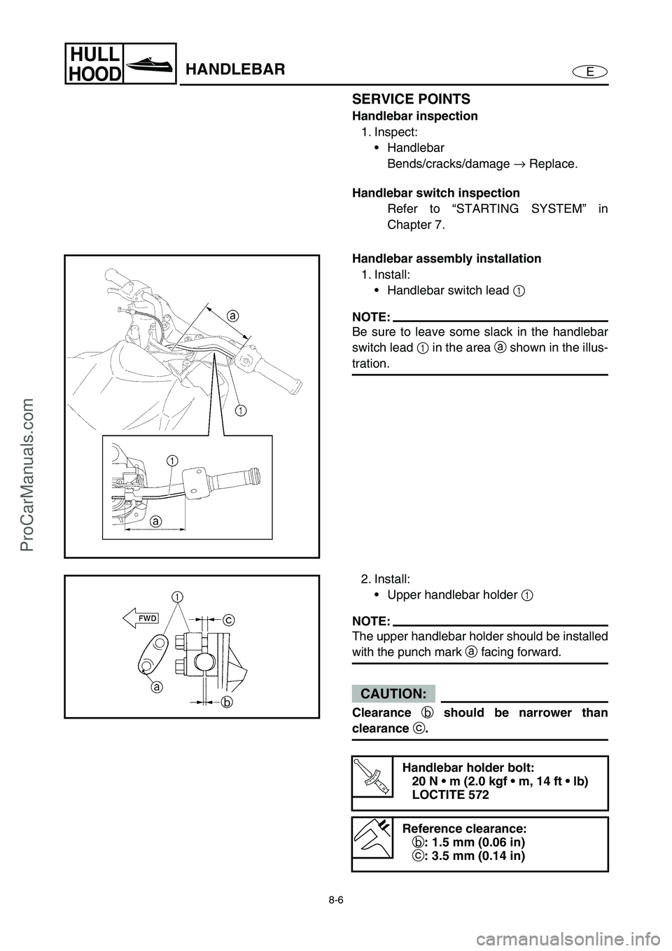
Handlebar assembly installation
1. Install:
Handlebar switch lead 1
NOTE:
Be sure to leave some slack in the handlebar
switch lead 1
in the area a
shown in the illus-
tration.
2. Install:
Upper handlebar holder 1
NOTE:
The upper handlebar holder should be installed
with the punch mark a
facing forward.
CAUTION:
Clearance
b should be narrower than
clearance
c.
T R..
Handlebar holder bolt:
20 N m (2.0 kgf m, 14 ft lb)
LOCTITE 572
Reference clearance:
b: 1.5 mm (0.06 in)
c: 3.5 mm (0.14 in)
ProCarManuals.com
Page 300 of 347
8-7
E
HULL
HOODHANDLEBAR
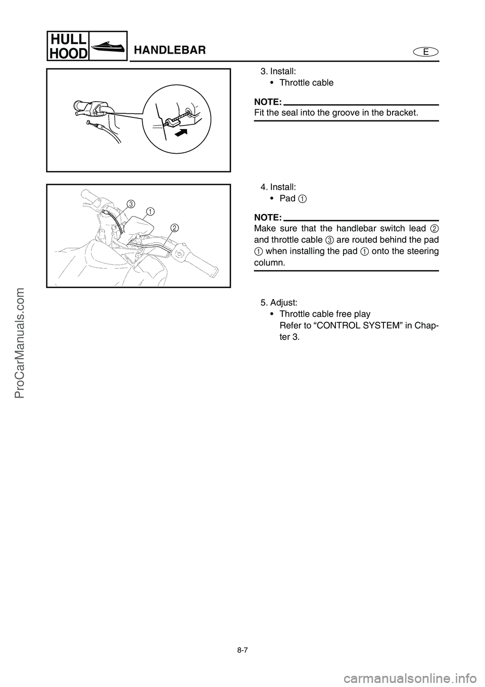
3. Install:
Throttle cable
NOTE:
Fit the seal into the groove in the bracket.
4. Install:
Pad 1
NOTE:
Make sure that the handlebar switch lead 2
and throttle cable 3
are routed behind the pad
1
when installing the pad 1
onto the steering
column.
5. Adjust:
Throttle cable free play
Refer to “CONTROL SYSTEM” in Chap-
ter 3.
ProCarManuals.com