ignition YAMAHA VX110 2005 Owner's Guide
[x] Cancel search | Manufacturer: YAMAHA, Model Year: 2005, Model line: VX110, Model: YAMAHA VX110 2005Pages: 347, PDF Size: 14.17 MB
Page 254 of 347

7-27
E
–+ELEC
Accelerator position sensor 1
output voltage at throttle lever
fully opened position:
3.75–4.35 V
Accelerator position sensor 2
output voltage at throttle lever
fully opened position:
3.50–4.50 V
Throttle valve opening angle at
throttle lever fully opened
position:
above 61°
Calculate the difference of the accelera-
tor position sensor 1 output voltage and
accelerator position sensor 2 output volt-
age at fully opened position.
Accelerator position sensor 1
output voltage – Accelerator
position sensor 2 output voltage
at fully opened position = below
0.75 V
Example:
If accelerator position sensor 1 output volt-
age is 4.009 V and accelerator position sen-
sor 2 output voltage is 3.896 V, then 4.009
– 3.896 = 0.113 V
Operate the throttle lever, and check that
the accelerator position sensor 1 and 2
output voltage changes continuously.
IGNITION SYSTEM
ProCarManuals.com
Page 255 of 347

7-28
E
–+ELEC
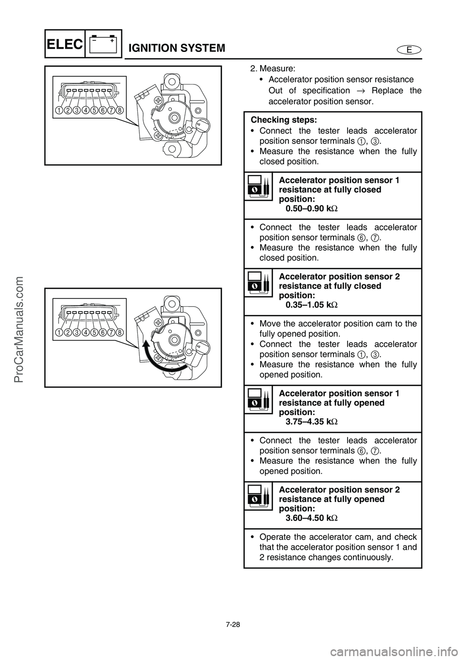
2. Measure:
• Accelerator position sensor resistance
Out of specification →
Replace the
accelerator position sensor.
Checking steps:
Connect the tester leads accelerator
position sensor terminals 1
, 3
.
Measure the resistance when the fully
closed position.
Accelerator position sensor 1
resistance at fully closed
position:
0.50–0.90 kΩ
Connect the tester leads accelerator
position sensor terminals 6
, 7
.
Measure the resistance when the fully
closed position.
Accelerator position sensor 2
resistance at fully closed
position:
0.35–1.05 kΩ
Move the accelerator position cam to the
fully opened position.
Connect the tester leads accelerator
position sensor terminals 1
, 3
.
Measure the resistance when the fully
opened position.
Accelerator position sensor 1
resistance at fully opened
position:
3.75–4.35 kΩ
Connect the tester leads accelerator
position sensor terminals 6
, 7
.
Measure the resistance when the fully
opened position.
Accelerator position sensor 2
resistance at fully opened
position:
3.60–4.50 kΩ
Operate the accelerator cam, and check
that the accelerator position sensor 1 and
2 resistance changes continuously.
14
5678 3 2
14
5678 3 2
IGNITION SYSTEM
ProCarManuals.com
Page 256 of 347

7-29
E
–+ELEC
CAM POSITION SENSOR
1. Measure:
Cam position sensor output voltage
Out of specification →
Replace.
NOTE:
The cam position sensor consists of two indi-
vidual sensors as shown in the illustration:
sensor 1 1
and sensor 2 2
.
To measure the output voltage, pass a
screwdriver under the cam position sensor at
measuring points A, B (center), and C in this
order.
When operating the Yamaha Diagnostic Sys-
tem, electric power is supplied to the cam
position sensor.
Test harness (3 pins):
New: YB-06877
Current: YB-06777
Test harness HM090-3 (3 pins):
New: 90890-06877
Current: 90890-06777
Cam position sensor output
voltage:
Green/orange (G/O) –
Black/orange (B/O)
Position Voltage (V)
A More than 4.8
B Less than 0.8
C More than 4.8
Measurement steps:
Remove the cam position sensor.
Connect the test harness to the cam
position sensor.
Operate the Yamaha Diagnostic System.
Pass a screwdriver under the cam posi-
tion sensor in the direction shown and
measure the output voltage.
1
2
A
B
C
IGNITION SYSTEM
ProCarManuals.com
Page 257 of 347

7-30
E
–+ELEC
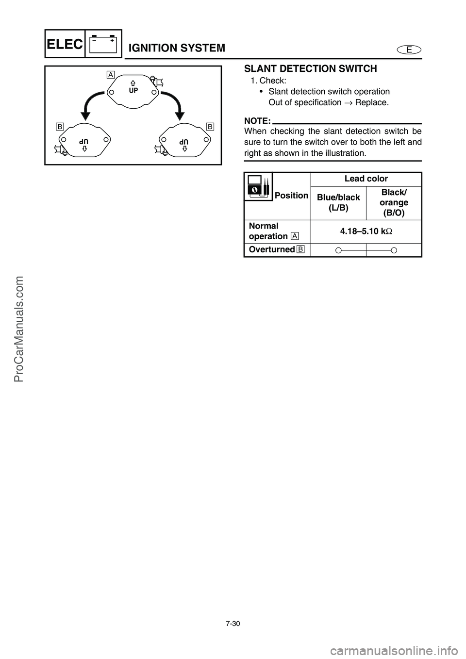
SLANT DETECTION SWITCH
1. Check:
Slant detection switch operation
Out of specification →
Replace.
NOTE:
When checking the slant detection switch be
sure to turn the switch over to both the left and
right as shown in the illustration.
PositionLead color
Blue/black
(L/B)Black/
orange
(B/O)
Normal
operation
È 4.18–5.10 k
Ω
Overturned
É
UP
UPUP
È
É É
IGNITION SYSTEM
ProCarManuals.com
Page 261 of 347

7-34
E
–+ELECFUEL CONTROL SYSTEM
FUEL INJECTOR
Refer to “FUEL INJECTION SYSTEM”
in Chapter 4.
MAIN AND FUEL PUMP RELAY
Refer to “IGNITION SYSTEM”.
OIL PRESSURE SWITCH
Refer to “INDICATION SYSTEM”.
THERMOSWITCH (ENGINE)
Refer to “IGNITION SYSTEM”.
THERMOSWITCH (EXHAUST)
Refer to “IGNITION SYSTEM”.
SLANT DETECTION SWITCH
Refer to “IGNITION SYSTEM”.
REMOTE CONTROL UNIT
(DELUXE MODEL ONLY)
Refer to “REMOTE CONTROL SYS-
TEM (DELUXE MODEL ONLY)”.
THROTTLE POSITION SENSOR
Refer to “IGNITION SYSTEM”.
ACCELERATOR POSITION SENSOR
Refer to “IGNITION SYSTEM”.
ProCarManuals.com
Page 265 of 347

7-38
E
–+ELECSTARTING SYSTEM
STARTER RELAY
1. Inspect:
Brown lead terminal
Black lead terminal
Loose →
Tighten.
2. Check:
Starter relay
Faulty →
Replace.
Checking steps:
Connect the tester leads between the
starter relay terminals as shown.
Connect the brown lead terminal to the
positive battery terminal.
Connect the black lead terminal to the
negative battery terminal.
Check that there is continuity between
the starter relay terminals.
Check that there is no continuity after the
brown or black lead is removed.
Br
B
REMOTE CONTROL UNIT
(DELUXE MODEL ONLY)
Refer to “REMOTE CONTROL SYS-
TEM (DELUXE MODEL ONLY)”.
THROTTLE POSITION SENSOR
Refer to “IGNITION SYSTEM”.
ACCELERATOR POSITION SENSOR
Refer to “IGNITION SYSTEM”.
ProCarManuals.com
Page 271 of 347

7-44
E
–+ELECCHARGING SYSTEM
FUSE
Refer to “STARTING SYSTEM”.
BATTERY
Refer to “ELECTRICAL” in Chapter 3.
LIGHTING COIL
Refer to “IGNITION SYSTEM”.
RECTIFIER/REGULATOR
Refer to “IGNITION SYSTEM”.
ProCarManuals.com
Page 274 of 347

7-47
E
–+ELECOFF THROTTLE STEERING SYSTEM
STEERING SENSOR
1. Check:
Steering sensor
Malfunction → Replace the steering
sensor.
Checking steps:
Turn the handlebar all the way to the left
or right, and then release it.
Install a plastic tie 1 loosely around the
center of the handlebar grip as shown.
Hook a spring gauge 2 onto the plastic
tie.
Hold the spring gauge at a 90° angle
from the handlebar, and then pull the
spring gauge with a force of 10 kgf
(22 lb).
When handlebar
pulledWhen handlebar
not pulled
ON OFF
Check that the following is displayed in
the “Engine Monitor” window of the
Yamaha Diagnostic System.
Use the same procedure to check that
the steering sensor operates correctly
when the handlebar is turned to both the
left and right. Replace the steering sen-
sor if it is a malfunction.
1
2
ECM
Refer to “IGNITION SYSTEM”.
PICKUP COIL
Refer to “IGNITION SYSTEM”.
THROTTLE POSITION SENSOR
Refer to “IGNITION SYSTEM”.
ACCELERATOR POSITION SENSOR
Refer to “IGNITION SYSTEM”.
ProCarManuals.com
Page 275 of 347

7-48
E
–+ELECINDICATION SYSTEM
INDICATION SYSTEM
WIRING DIAGRAM
10A
10A
3A
30A20A
RR
BBR
BBr
BBr
B/OW/B
B/O
B/O
WR
Y
G
O
BW
Y
W
G/OW/B
Y/GR/Y
B
PB
Pu/RPu/B
Pu/GPu/Y
P/W
B/G
R/Y
W/B
B/Y
Y/WL/R
B/RB/W
B
B
BBP
P
PBBP
R/Y
B/G
G/OB/OG/O
P/W
B/OB/YB/YR/Y
R/Y
R/Y
B/LL/YL/B
R/YPu/G
Pu/Y
Pu/B
Pu/RR/Y
R/Y
R/Y
R/YB/YR/Y
R/Y
B/O
B/RR/Y
R/Y
R/YY/W
Y/GL/R
Y
P
P
O
O
R
R
R
B
G
BR
Y
B/YR/W
BRW
P
PB
B/LL/R
L/RL/B
B/WR
BW/BR/YL/RL/YL/B Gy B/G
YB/YR/Y
98
A
A A
A
G
G GG
H IJ K4 3
5
67 2 1
0
0 0
0
B
C
D
E
F LM
N
1Battery
2Fuse (30 A)
3Fuse (20 A)
4Fuse (3 A)
5Fuse (10 A)
6Fuse (10 A)
7Starter relay
8Main and fuel pump relay9Electronic control throttle valve
relay
0Ignition coil
ASpark plug
BCam position sensor
CEngine temperature sensor
DThermoswitch (engine)
EThermoswitch (exhaust)
FOil pressure switchGFuel injector
HRemote control unit
(Deluxe model only)
IECM
JPickup coil
KBuzzer
LFuel sender
MSpeed sensor
NMultifunction meter
ProCarManuals.com
Page 277 of 347

7-50
E
–+ELECINDICATION SYSTEM
FUSE
Refer to “STARTING SYSTEM”.
BATTERY
Refer to “ELECTRICAL” in Chapter 3.
MAIN AND FUEL PUMP RELAY
Refer to “IGNITION SYSTEM”.
ECM
Refer to “IGNITION SYSTEM”.
ENGINE TEMPERATURE SENSOR
Refer to “IGNITION SYSTEM”.
THERMOSWITCH (ENGINE)
Refer to “IGNITION SYSTEM”.
THERMOSWITCH (EXHAUST)
Refer to “IGNITION SYSTEM”.
REMOTE CONTROL UNIT
(DELUXE MODEL ONLY)
Refer to “REMOTE CONTROL SYS-
TEM (DELUXE MODEL ONLY)”.
BUZZER
1. Check:
Buzzer
Buzzer does not sound → Replace.
Checking steps:
Connect the battery (12 V) to the buzzer
coupler as shown.
Battery positive terminal →
Red (R) terminal 1
Battery negative terminal →
Black (B) terminal 2
ProCarManuals.com