ignition YAMAHA VX110 2005 Owner's Manual
[x] Cancel search | Manufacturer: YAMAHA, Model Year: 2005, Model line: VX110, Model: YAMAHA VX110 2005Pages: 347, PDF Size: 14.17 MB
Page 244 of 347

7-17
E
–+ELEC
NOTE:
To crank the engine, connect the engine shut-
off cord (lanyard) to the engine shut-off switch,
and then press the start switch and engine
stop switch simultaneously.
4. Measure:
Rectifier/regulator output voltage
Below specification →
Replace the recti-
fier/regulator.
NOTE:
Do not use the peak voltage adapter to mea-
sure the output voltage.
Disconnect the output lead of the tester har-
ness.
Test harness (6 pins):
YB-06848
Test harness FSW-6A (6 pins):
90890-06848
Rectifier/regulator output
voltage:
Red (R) – Black (B)
r/minUnloaded
3,500
V 13.0
BATTERY
Refer to “ELECTRICAL” in Chapter 3.
FUSE
Refer to “STARTING SYSTEM”.
SPARK PLUGS
Refer to “POWER UNIT” in Chapter 3.
IGNITION SYSTEM
ProCarManuals.com
Page 245 of 347

7-18
E
–+ELEC
IGNITION COIL
1. Measure:
Primary coil resistance
Out of specification →
Replace.
NOTE:
When measuring a resistance of 10 Ω
or less
using a digital tester, the correct measurement
cannot be obtained because of the tester’s
internal resistance.
Refer to “Low resistance measurement”.
Primary coil resistance:
1.19–1.61
Ω at 20 °C (68 °F)
2. Measure:
Secondary coil resistance
Out of specification →
Replace.
Secondary coil resistance:
8.5–11.5 k
Ω at 20 °C (68 °F)
ENGINE STOP SWITCH
1. Check:
Engine stop switch continuity
Out of specification →
Replace.
Engine stop switch continuity
(black coupler)
Clip PositionLead color
White Black
InstalledFree
Push
RemovedFree
Push
IGNITION SYSTEM
ProCarManuals.com
Page 246 of 347

7-19
E
–+ELECIGNITION SYSTEM
ENGINE TEMPERATURE SENSOR
1. Measure:
Engine temperature sensor resistance
(at the specified temperature)
Out of specification →
Replace.
Engine temperature sensor
resistance:
20 °C (68 °F): 54.2–69.0 k
Ω
100 °C (212 °F): 3.12–3.48 k
Ω
Measurement steps:
Suspend the engine temperature sensor
in a container filled with water.
Place a thermometer in the water.
Slowly heat the water.
Measure the resistance when the speci-
fied temperature is reached.
SENSOR ASSEMBLY
1. Check:
Intake air temperature sensor
Out of specification →
Replace the sen-
sor assembly.
Checking steps:
Measure the ambient temperature.
Connect a computer to the watercraft and
use the Yamaha Diagnostic System to
display the intake air temperature.
If the ambient temperature and the dis-
played intake air temperature differ by
more than ±
5 °C (±
9 °F), replace the
sensor assembly.
ProCarManuals.com
Page 247 of 347

7-20
E
–+ELECIGNITION SYSTEM
THERMOSWITCH (ENGINE)
1. Check:
Thermoswitch (engine) continuity
(at the specified temperature)
Out of specification →
Replace.
1 No continuity
È Temperature
2 Continuity
É Time
NOTE:
The thermoswitch (engine) connector is blue.
Thermoswitch (engine) continuity
temperature:
a 84–90 °C (183–194 °F)
b 70–84 °C (158–183 °F)
Checking steps:
Suspend the thermoswitch (engine) in a
container filled with water.
Place a thermometer in the water.
Slowly heat the water.
Measure the continuity when the speci-
fied temperature is reached.
ProCarManuals.com
Page 248 of 347

7-21
E
–+ELEC
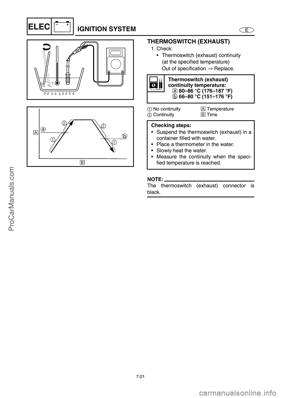
THERMOSWITCH (EXHAUST)
1. Check:
Thermoswitch (exhaust) continuity
(at the specified temperature)
Out of specification →
Replace.
1 No continuity
È Temperature
2 Continuity
É Time
NOTE:
The thermoswitch (exhaust) connector is
black.
Thermoswitch (exhaust)
continuity temperature:
a 80–86 °C (176–187 °F)
b 66–80 °C (151–176 °F)
Checking steps:
Suspend the thermoswitch (exhaust) in a
container filled with water.
Place a thermometer in the water.
Slowly heat the water.
Measure the continuity when the speci-
fied temperature is reached.
IGNITION SYSTEM
ProCarManuals.com
Page 249 of 347

7-22
E
–+ELECIGNITION SYSTEM
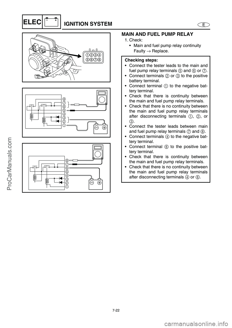
MAIN AND FUEL PUMP RELAY
1. Check:
• Main and fuel pump relay continuity
Faulty → Replace.
Checking steps:
Connect the tester leads to the main and
fuel pump relay terminals 5 and 6 or 7.
Connect terminals 2 or 3 to the positive
battery terminal.
Connect terminal 1 to the negative bat-
tery terminal.
Check that there is continuity between
the main and fuel pump relay terminals.
Check that there is no continuity between
the main and fuel pump relay terminals
after disconnecting terminals 1, 2, or
3.
Connect the tester leads between main
and fuel pump relay terminals 7 and 8.
Connect terminals 4 to the negative bat-
tery terminal.
Connect terminal 6 to the positive bat-
tery terminal.
Check that there is continuity between
the main and fuel pump relay terminals.
Check that there is no continuity between
the main and fuel pump relay terminals
after disconnecting terminals 4 or 6.
–+
8
7
6
5
4
3
2
1
–+
8
7
6
5
4
3
2
1
ProCarManuals.com
Page 250 of 347

7-23
E
–+ELEC
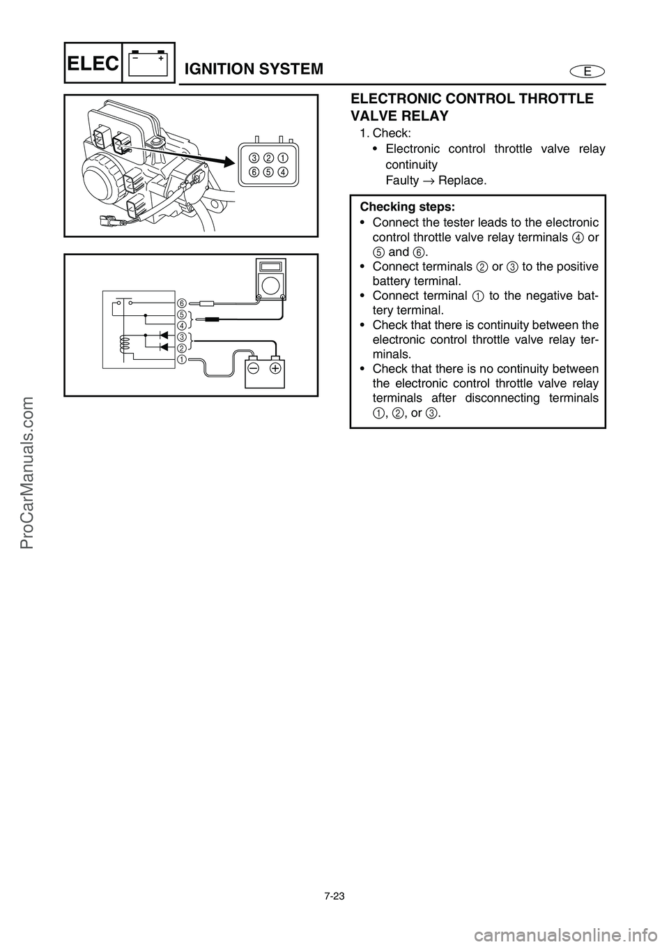
ELECTRONIC CONTROL THROTTLE
VALVE RELAY
1. Check:
Electronic control throttle valve relay
continuity
Faulty →
Replace.
Checking steps:
Connect the tester leads to the electronic
control throttle valve relay terminals 4
or
5
and 6
.
Connect terminals 2
or 3
to the positive
battery terminal.
Connect terminal 1
to the negative bat-
tery terminal.
Check that there is continuity between the
electronic control throttle valve relay ter-
minals.
Check that there is no continuity between
the electronic control throttle valve relay
terminals after disconnecting terminals
1
, 2
, or 3
.
–+
6
5
4
3
2
1
IGNITION SYSTEM
ProCarManuals.com
Page 251 of 347

7-24
E
–+ELECIGNITION SYSTEM
THROTTLE POSITION SENSOR
1. Measure:
Throttle position sensor output voltage
Out of specification →
Replace the
throttle body assembly.
Checking steps:
CAUTION:
Do not loosen the throttle stop screw nut
and do not turn the throttle stop screw.
Connect a computer to the watercraft and
use the Yamaha Diagnostic System to
display the “throttle position sensor 1 out-
put voltage”, “throttle valve opening
angle”, and “throttle position sensor 2
output voltage”.
Release the throttle lever to the fully
closed position.
Check the output voltage of throttle posi-
tion sensor 1 and the throttle valve open-
ing angle.
1Throttle position sensor 1
2Throttle position sensor 2
ÈThrottle position sensor output voltage
ÉThrottle valve opening angle
ÊFully closed
ËFully open
NOTE:
The actual throttle position sensor output
voltage and throttle valve opening angle
may vary according to environmental condi-
tions.
Throttle position sensor 1 output
voltage with throttle lever fully
closed:
0.45–0.95 V (reference data)
Throttle valve opening angle with
throttle lever fully closed:
–1.1–9.4° (reference data)
2 ± 0.1 V
0.5 ± 0.05 V 4.65
± 0.05 V
(4.5 V)
(10˚)
É
ÊË È1 2
ProCarManuals.com
Page 252 of 347

7-25
E
–+ELECIGNITION SYSTEM
Squeeze the throttle lever to the fully
open position and hold it.
Check the output voltage of throttle posi-
tion sensor 2 and the throttle valve open-
ing angle.
Throttle position sensor 2 output
voltage with throttle lever fully
open:
4.60–4.70 V
Throttle valve opening angle with
throttle lever fully open:
above 80° (reference data)
Release the throttle lever from the fully
open position to the fully closed position
slowly and check the output voltage of
throttle position sensor 2 and the throttle
valve opening angle.
Hold the throttle lever when the output
voltage of throttle position sensor 2 is
below 4.5 V and the throttle valve open-
ing angle is above 10°.
Calculate the difference of the output
voltage of throttle position sensor 1 and
the output voltage of throttle position sen-
sor 2.
Throttle position sensor 2 output
voltage – throttle position sensor
1 output voltage = 1.9–2.1 V
Example:
If the output voltage of throttle position sen-
sor 1 is 2.5 V and the output voltage of
throttle position sensor 2 is 4.5 V, then
4.5 – 2.5 = 2.0 V
Operate the throttle lever and check that
the output voltage of throttle position sen-
sors 1 and 2 changes continuously.
NOTE:
The maximum output voltage of throttle
position sensor 2 is 4.65 ±
0.05 V at the half
open position.
ProCarManuals.com
Page 253 of 347

7-26
E
–+ELECIGNITION SYSTEM
ACCELERATOR POSITION SENSOR
1. Measure:
Accelerator position sensor output volt-
age
Out of specification →
Replace the
accelerator position sensor.
Checking steps:
Connect a computer to the watercraft and
use the Yamaha Diagnostic System to
display the “accelerator position sensor
1” and “accelerator position sensor 2”.
Release the throttle lever to the fully
closed position.
Check that the accelerator position sen-
sor 1 and 2 output voltage.
NOTE:
The actual accelerator position sensor out-
put voltage and throttle valve opening angle
may vary according to environmental condi-
tions.
Accelerator position sensor 1
output voltage at throttle lever
fully closed position:
0.50–0.90 V
Accelerator position sensor 2
output voltage at throttle lever
fully closed position:
0.35–1.05 V
Throttle valve opening angle at
throttle lever fully closed
position:
2.7–4.8°
Squeeze the throttle lever to the fully
open position and hold it.
Check that the accelerator position sen-
sor 1 and 2 output voltage.
ProCarManuals.com