ignition YAMAHA VX110 2005 User Guide
[x] Cancel search | Manufacturer: YAMAHA, Model Year: 2005, Model line: VX110, Model: YAMAHA VX110 2005Pages: 347, PDF Size: 14.17 MB
Page 105 of 347

5-6
EPOWRENGINE UNIT
7. Install:
Ignition coils
T R..
Ignition coils bolt:
7.6 N m (0.76 kgf m, 5.5 ft lb)
LOCTITE 572
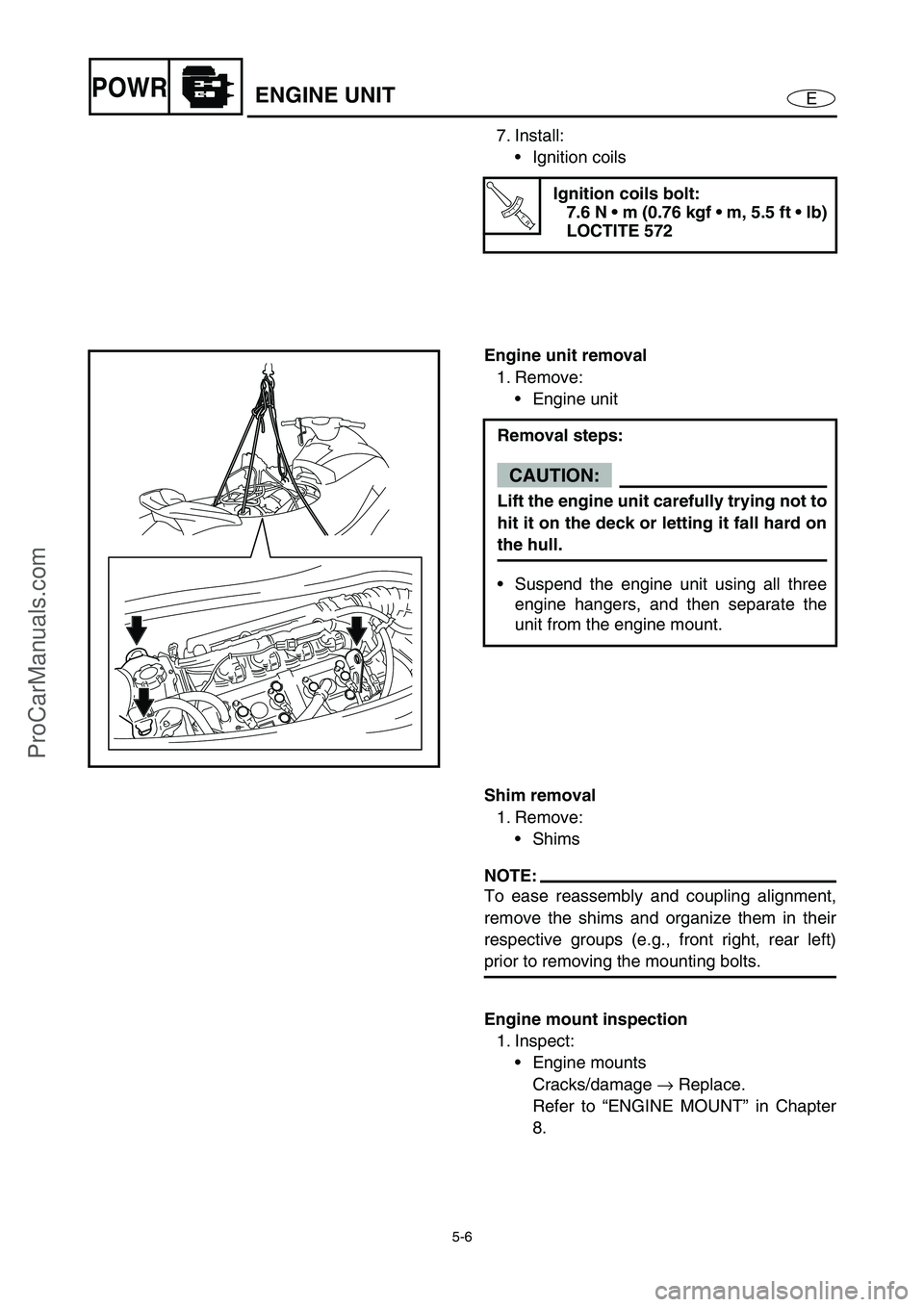
Engine unit removal
1. Remove:
Engine unit
Removal steps:
CAUTION:
Lift the engine unit carefully trying not to
hit it on the deck or letting it fall hard on
the hull.
Suspend the engine unit using all three
engine hangers, and then separate the
unit from the engine mount.
Shim removal
1. Remove:
Shims
NOTE:
To ease reassembly and coupling alignment,
remove the shims and organize them in their
respective groups (e.g., front right, rear left)
prior to removing the mounting bolts.
Engine mount inspection
1. Inspect:
Engine mounts
Cracks/damage →
Replace.
Refer to “ENGINE MOUNT” in Chapter
8.
ProCarManuals.com
Page 140 of 347

5-41
EPOWRCAMSHAFTS
CAMSHAFTS
EXPLODED DIAGRAM
REMOVAL AND INSTALLATION CHART
Step Procedure/Part name Q’ty Service points
CYLINDER HEAD COVER
REMOVALFollow the left “Step” for removal.
1Bolt 4
2 Ignition coil 4
3 Spark plug 4
4 Clamp/breather hose 1/1È
To oil tank
Paint mark a
5Bolt 1
6 Cam position sensor 1
7 Clamp/cooling water hose 1/1É
To transom plate
8 Rubber seal 1
E
4
65
7 8
10
11
12
13 9
LT
572
LT
14
16
15
3
13 N
m (1.3 kgf m, 9.4 ft Ib)
10 N
m (1.0 kgf m, 7.2 ft Ib)
6 × 16 mm 6 × 16 mm
2nd 7.6 N m (0.76 kgf
m, 5.5 ft
Ib) 1st 3.7 N m (0.37 kgf
m, 2.7 ft
Ib)
12 N
m (1.2 kgf m, 8.7 ft Ib)
6 × 22 mm
aÈ
É
1
2
7.6 N
m (0.76 kgf m, 5.5 ft Ib)
6 × 16 mm
LT
572
LTAA
1280B
1280B
ProCarManuals.com
Page 225 of 347

E
–+ELEC
1
2
3
4
5
6
7
8
9
CHAPTER 7
ELECTRICAL SYSTEM
ELECTRICAL COMPONENTS........................................................................ 7-1
FUSE BOX ....................................................................................................... 7-2
EXPLODED DIAGRAM ............................................................................. 7-2
REMOVAL AND INSTALLATION CHART ................................................ 7-2
ECM AND RECTIFIER/REGULATOR............................................................. 7-7
EXPLODED DIAGRAM ............................................................................. 7-7
REMOVAL AND INSTALLATION CHART ................................................ 7-7
ELECTRICAL ANALYSIS ............................................................................... 7-9
INSPECTION............................................................................................. 7-9
Digital tester ........................................................................................ 7-9
Low resistance measurement ........................................................... 7-10
Peak voltage measurement .............................................................. 7-10
Peak voltage adapter ........................................................................ 7-11
Test harness .................................................................................... 7-11
IGNITION SYSTEM ....................................................................................... 7-12
WIRING DIAGRAM ................................................................................. 7-12
IGNITION SPARK ................................................................................... 7-14
IGNITION SYSTEM PEAK VOLTAGE .................................................... 7-15
BATTERY ................................................................................................ 7-17
FUSE ....................................................................................................... 7-17
SPARK PLUGS ....................................................................................... 7-17
IGNITION COIL ....................................................................................... 7-18
ENGINE STOP SWITCH ......................................................................... 7-18
ENGINE TEMPERATURE SENSOR ...................................................... 7-19
SENSOR ASSEMBLY ............................................................................. 7-19
THERMOSWITCH (ENGINE).................................................................. 7-20
THERMOSWITCH (EXHAUST) .............................................................. 7-21
MAIN AND FUEL PUMP RELAY............................................................. 7-22
ELECTRONIC CONTROL THROTTLE VALVE RELAY ......................... 7-23
THROTTLE POSITION SENSOR ........................................................... 7-24
ACCELERATOR POSITION SENSOR ................................................... 7-26
CAM POSITION SENSOR ...................................................................... 7-29
SLANT DETECTION SWITCH ................................................................ 7-30
ProCarManuals.com
Page 228 of 347

7-1
E
–+ELECELECTRICAL COMPONENTS
ELECTRICAL COMPONENTS
O
N
M
L
K
J
I
H
G
F
E
D
C
B
A
0
91
2
3
4
5
6
7
8
1Thermoswitch (engine)
2Fuse box
3Slant detection switch
4Starter motor
5Engine temperature sensor
6Spark plugs and ignition coils
7Cam position sensor
8Battery
9Speed sensor
0Sensor assembly (intake air
pressure and intake air tem-
perature)AOil pressure switch
BFuel injectors
CThermoswitch (exhaust)
DRectifier/regulator
EECM
FThrottle body assembly
GLighting coil and pickup coil
HEngine stop switch, engine
shut-off switch, and start
switch
ISteering sensor
JBuzzerKAccelerator position sensor
LElectric fuel pump
MFuel sender
NMultifunction meter
ORemote control unit (Deluxe
model only)
ProCarManuals.com
Page 237 of 347

7-10
E
–+ELECELECTRICAL ANALYSIS
Low resistance measurement
NOTE:
When measuring a resistance of 10 Ω
or less
using a digital tester, the correct measure-
ment cannot be obtained because of the
tester’s internal resistance.
To obtain the correct value, subtract the
internal resistance from the displayed mea-
surement.
The internal resistance of the tester can be
obtained by connecting both of its terminals.
Correct value =
Displayed measurement –
Internal resistance
Peak voltage measurement
NOTE:
When checking the condition of the ignition
system it is vital to know the peak voltage.
Cranking speed is dependant on many fac-
tors (e.g., fouled or weak spark plugs, a
weak battery). If one of these is defective,
the peak voltage will be lower than specifica-
tion.
If the peak voltage measurement is not
within specification the engine will not oper-
ate properly.
A low peak voltage will also cause compo-
nents to prematurely wear.
ProCarManuals.com
Page 239 of 347

7-12
E
–+ELECIGNITION SYSTEM
IGNITION SYSTEM
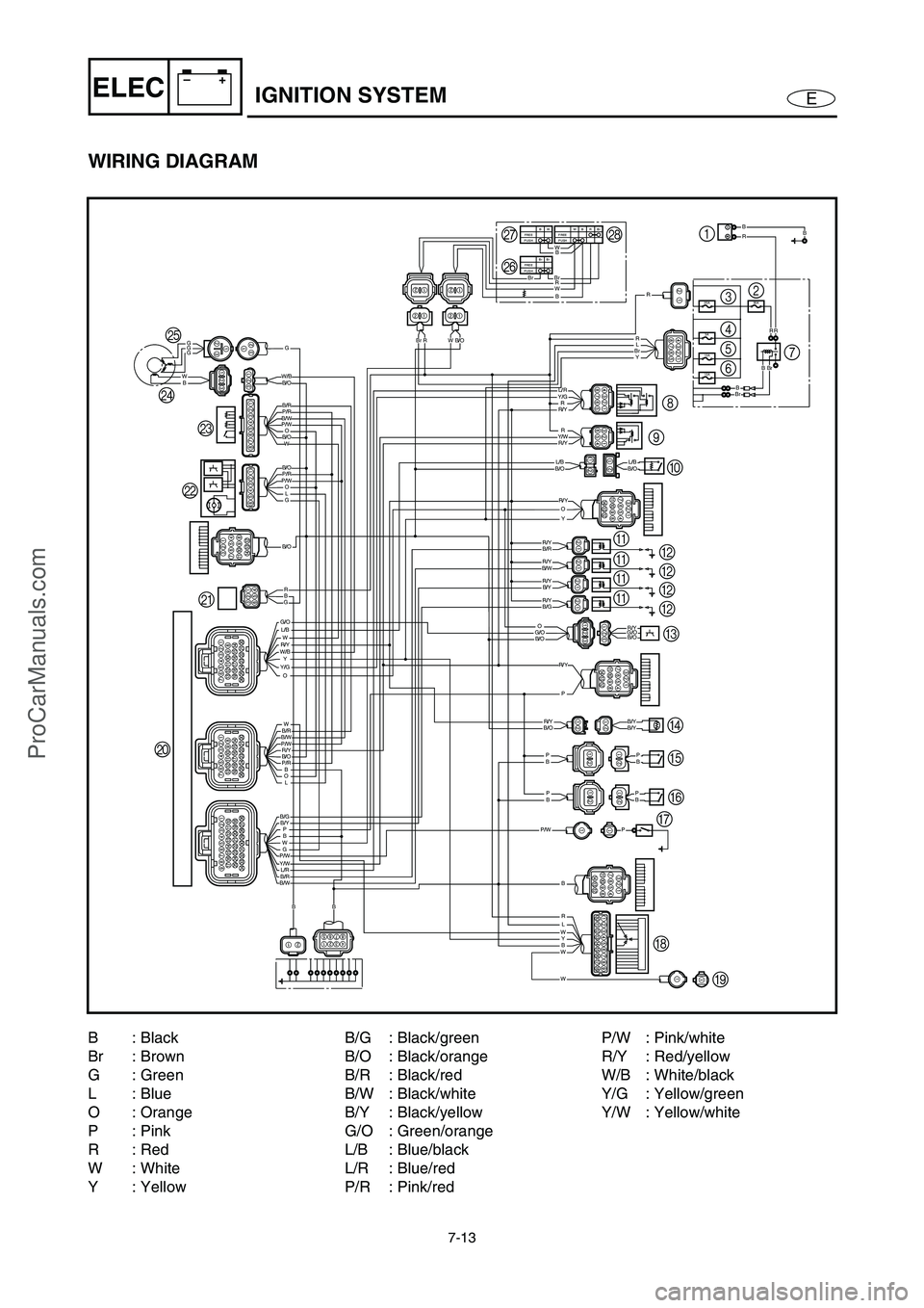
WIRING DIAGRAM
10A
10A
3A
30A20A
WBrBRFREE
PUSHBWFREE
PUSH
Br BrFREE
PUSH
BW
W
BrBrBrBrR
W
B/W
B/O
B/O
B/O
B/R
P/R
P/R
W/B
P/W
P/W
B/O
L/B
B/WB/R
B/OP/W
P/R
W
W
WLR
Y
G
O
O
W
GG
BW
GG
O
OLG
W
Y
W
G/O
W/BR/Y
Y/G
BL
PBWP/W
B/GB/Y
Y/WL/RB/RB/W
B
B
BBP
P
P
BBP
RR
BBR
R/Y
B/OL/BB/OL/B
B/G
G/OB/OG/O
P/W
B/OB/YB/YR/Y
R/Y
R/Y
R/YB/YR/Y
R/Y
B/O
B/RR/Y
R/Y
R/YY/W
Y/GL/R
Y
P
P
O
O R
R
R
BB
BrRB/O
BBr
B/W
Y BrL R B
R
GB
R/YBBr
4
0 98
B
B B
B
H
I JK LM NOQ
PR
3
5
67 2 1
A
A A
A
C
D
E
F
G
1Battery
2Fuse (30 A)
3Fuse (20 A)
4Fuse (3 A)
5Fuse (10 A)
6Fuse (10 A)
7Starter relay
8Main and fuel pump
relay9Electronic control
throttle valve relay
0Slant detection switch
AIgnition coil
BSpark plug
CCam position sensor
DEngine temperature
sensor
EThermoswitch
(engine)FThermoswitch
(exhaust)
GOil pressure switch
HRemote control unit
(Deluxe model only)
IAntenna
(Deluxe model only)
JECM
KRectifier/regulatorLThrottle body assem-
bly
MAccelerator position
sensor
NPickup coil
OLighting coil
PStart switch
QEngine stop switch
REngine shut-off switch
ProCarManuals.com
Page 240 of 347

7-13
E
–+ELECIGNITION SYSTEM
WIRING DIAGRAM
10A
10A
3A
30A20A
WBrBRFREE
PUSHBWFREE
PUSH
Br BrFREE
PUSH
BW
W
BrBrBrBrR
W
B/W
B/O
B/O
B/O
B/R
P/R
P/R
W/B
P/W
P/W
B/O
L/B
B/WB/R
B/OP/W
P/R
W
W
WLR
Y
G
O
O
W
GG
BW
GG
O
OLG
W
Y
W
G/O
W/BR/Y
Y/G
BL
PBWP/W
B/GB/Y
Y/WL/RB/RB/W
B
B
BBP
P
P
BBP
RR
BBR
R/Y
B/OL/BB/OL/B
B/G
G/OB/OG/O
P/W
B/OB/YB/YR/Y
R/Y
R/Y
R/YB/YR/Y
R/Y
B/O
B/RR/Y
R/Y
R/YY/W
Y/GL/R
Y
P
P
O
O R
R
R
BB
BrRB/O
BBr
B/W
Y BrL R B
R
GB
R/YBBr
4
0 98
B
B B
B
H
I JK LM NOQ
PR
3
5
67 2 1
A
A A
A
C
D
E
F
G
B: Black
Br : Brown
G: Green
L: Blue
O : Orange
P: Pink
R: Red
W: White
Y : YellowB/G : Black/green
B/O : Black/orange
B/R : Black/red
B/W : Black/white
B/Y : Black/yellow
G/O : Green/orange
L/B : Blue/black
L/R : Blue/red
P/R : Pink/redP/W : Pink/white
R/Y : Red/yellow
W/B : White/black
Y/G : Yellow/green
Y/W : Yellow/white
ProCarManuals.com
Page 241 of 347

7-14
E
–+ELECIGNITION SYSTEM
IGNITION SPARK
WARNING
When checking the spark gap, do not
touch any of the connections of the spark
checker/ignition tester lead wires.
When performing the spark gap test, take
special care not to let sparks leak out of
the removed spark plug cap.
When performing the spark gap check,
keep flammable gas or liquids away,
since this test can produce sparks.
1. Check:
Ignition spark
Weak →
Check the ECM output peak
voltage.
Check the ignition coil for resistance.
Checking steps:
Connect the spark plug cap to the special
service tool.
Spark checker:
YM-34487
Ignition tester:
90890-06754
Crank the engine and observe the igni-
tion system spark through the discharge
window.
OK
ProCarManuals.com
Page 242 of 347

7-15
E
–+ELECIGNITION SYSTEM
IGNITION SYSTEM PEAK VOLTAGE
WARNING
When checking the electrical components,
do not touch any of the connections of the
digital tester lead wires.
NOTE:
If there is no spark, or the spark is weak,
continue with the ignition system test.
If a good spark is obtained, the problem is
not with the ignition system, but possibly with
the spark plug(s) or another component.
1. Measure:
ECM output peak voltage
Below specification →
Measure the
pickup coil output peak voltage.
NOTE:
When measuring the ECM output peak volt-
age while cranking the engine, disconnect
the ignition coil couplers for all cylinders
except for the cylinder being measured.
To crank the engine, connect the engine
shut-off cord (lanyard) to the engine shut-off
switch, and then press the start switch.
Test harness (2 pins):
New: YB-06867
Current: YB-06767
Test harness FWY-2 (2 pins):
New: 90890-06867
Current: 90890-06767
ECM output peak voltage:
Black/red (B/R) –
Red/yellow (R/Y)
Black/white (B/W) –
Red/yellow (R/Y)
Black/yellow (B/Y) –
Red/yellow (R/Y)
Black/green (B/G) –
Red/yellow (R/Y)
r/minLoaded
Cranking 2,000 3,500
V 90 130 140
ProCarManuals.com
Page 243 of 347

7-16
E
–+ELECIGNITION SYSTEM
2. Measure:
Pickup coil output peak voltage
Below specification →
Replace the
pickup coil.
Above specification →
Replace the
ECM.
NOTE:
To crank the engine, connect the engine shut-
off cord (lanyard) to the engine shut-off switch,
and then press the start switch and engine
stop switch simultaneously.
Test harness (3 pins):
New: YB-06877
Current: YB-06777
Test harness HM090-3 (3 pins):
New: 90890-06877
Current: 90890-06777
Pickup coil output peak voltage:
White/black (W/B) –
Black/orange (B/O)
r/minUnloaded Loaded
Cranking 2,000 3,500
V 8.0 6.9 19.4 25.1
3. Measure:
Lighting coil output peak voltage
Below specification →
Replace the light-
ing coil.
Test harness (3 pins):
New: YB-06870
Current: YB-06770
Test harness SMT250-3 (3 pins):
New: 90890-06870
Current: 90890-06770
Lighting coil output peak voltage:
Green (G) – Green (G)
r/minUnloaded
Cranking 2,000 3,500
V 7.8 24.5 41.6
ProCarManuals.com