diagram YAMAHA VX110 2005 Service Manual
[x] Cancel search | Manufacturer: YAMAHA, Model Year: 2005, Model line: VX110, Model: YAMAHA VX110 2005Pages: 347, PDF Size: 14.17 MB
Page 5 of 347
E
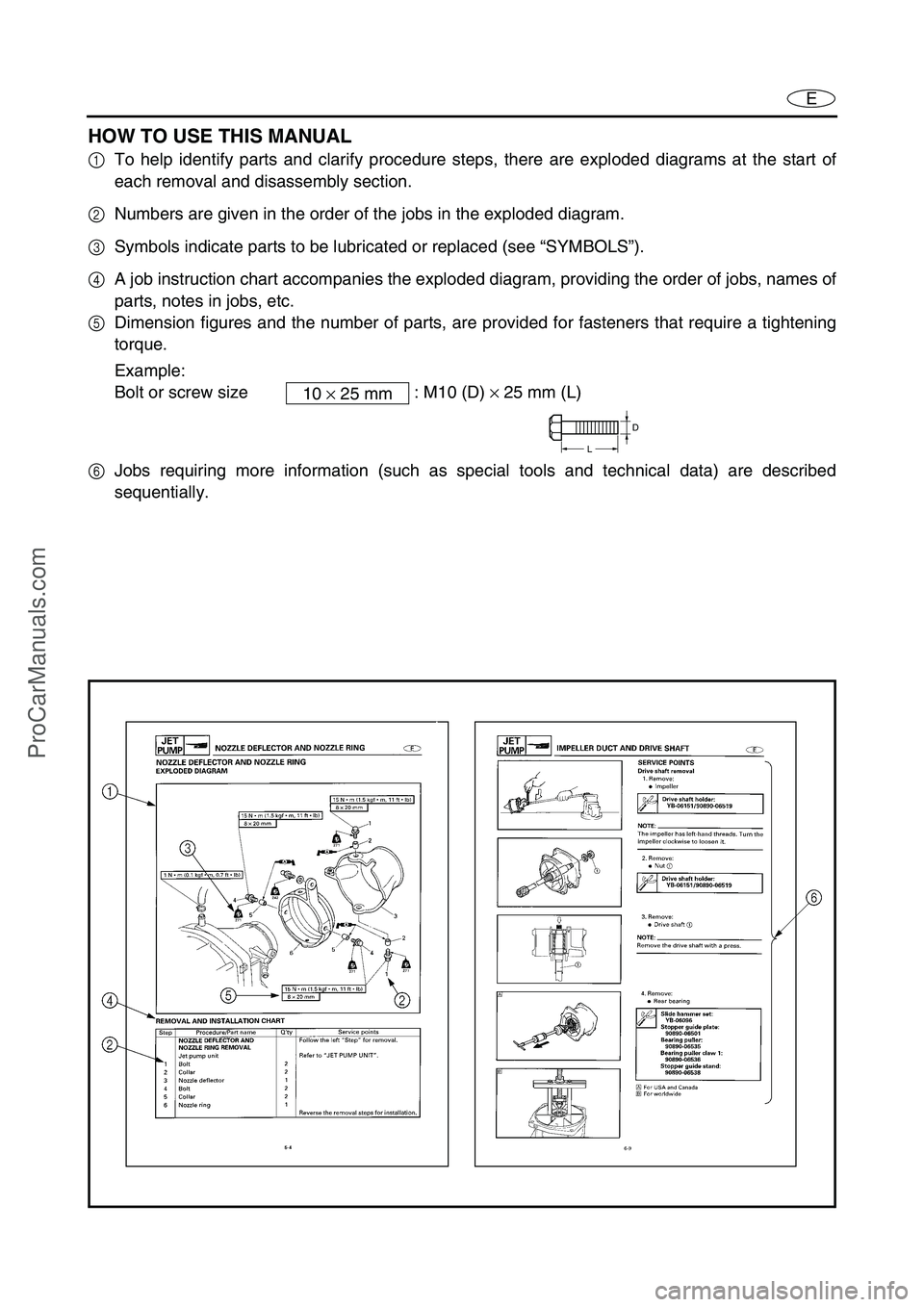
HOW TO USE THIS MANUAL
1To help identify parts and clarify procedure steps, there are exploded diagrams at the start of
each removal and disassembly section.
2Numbers are given in the order of the jobs in the exploded diagram.
3Symbols indicate parts to be lubricated or replaced (see “SYMBOLS”).
4A job instruction chart accompanies the exploded diagram, providing the order of jobs, names of
parts, notes in jobs, etc.
5Dimension figures and the number of parts, are provided for fasteners that require a tightening
torque.
Example:
Bolt or screw size : M10 (D) × 25 mm (L)
6Jobs requiring more information (such as special tools and technical data) are described
sequentially.10 × 25 mm
D
L
ProCarManuals.com
Page 6 of 347
E
A50001-1-4
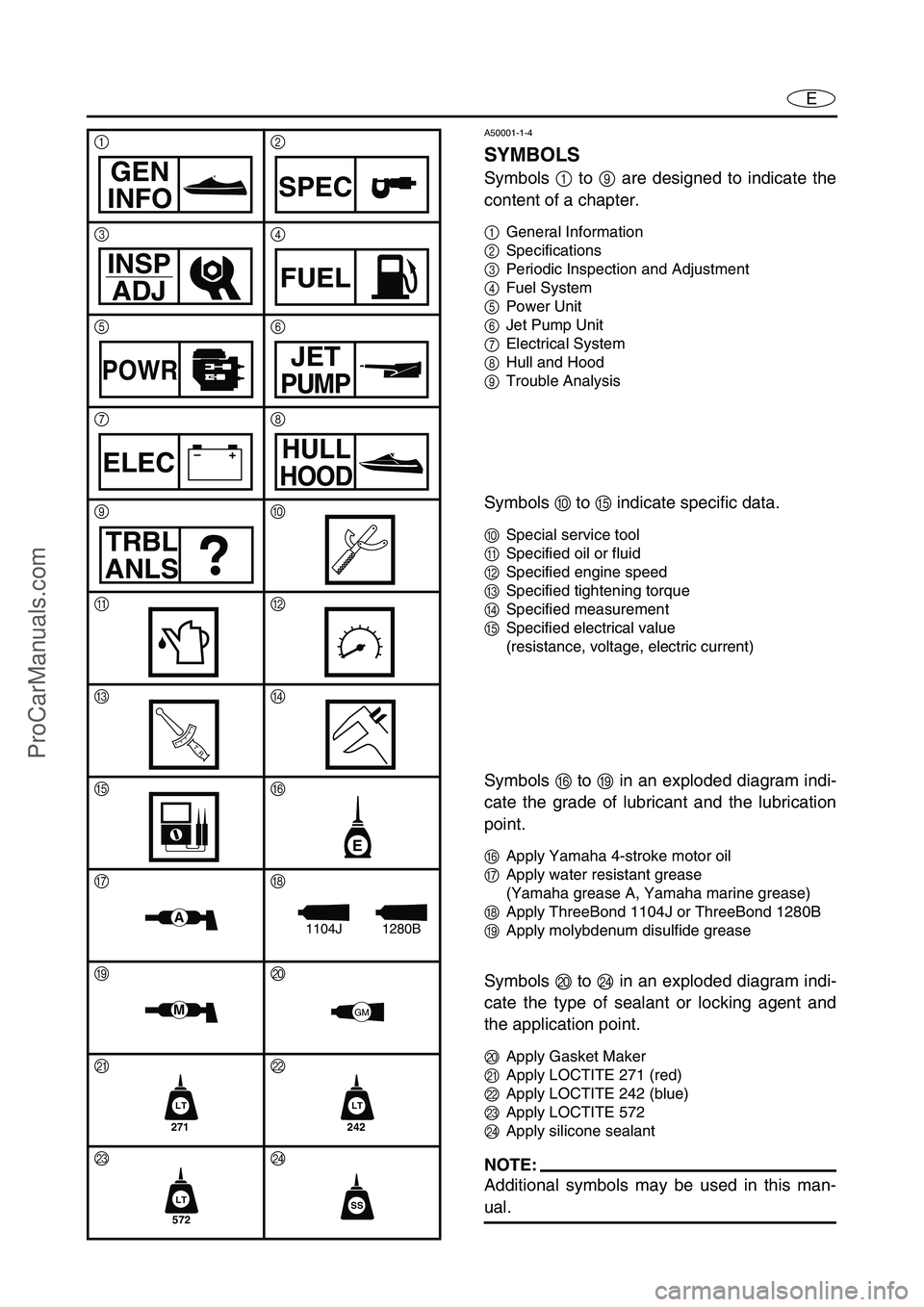
SYMBOLS
Symbols 1 to 9 are designed to indicate the
content of a chapter.
1General Information
2Specifications
3Periodic Inspection and Adjustment
4Fuel System
5Power Unit
6Jet Pump Unit
7Electrical System
8Hull and Hood
9Trouble Analysis
Symbols 0 to E indicate specific data.
0Special service tool
ASpecified oil or fluid
BSpecified engine speed
CSpecified tightening torque
DSpecified measurement
ESpecified electrical value
(resistance, voltage, electric current)
Symbols F to I in an exploded diagram indi-
cate the grade of lubricant and the lubrication
point.
FApply Yamaha 4-stroke motor oil
GApply water resistant grease
(Yamaha grease A, Yamaha marine grease)
HApply ThreeBond 1104J or ThreeBond 1280B
IApply molybdenum disulfide grease
Symbols J to N in an exploded diagram indi-
cate the type of sealant or locking agent and
the application point.
JApply Gasket Maker
KApply LOCTITE 271 (red)
LApply LOCTITE 242 (blue)
MApply LOCTITE 572
NApply silicone sealant
NOTE:
Additional symbols may be used in this man-
ual.
12
34
56
78
90
AB
CD
EF
GH
IJ
KL
MN
GEN
INFOSPEC
INSP
ADJFUEL
POWRJET
PUMP
–+ELECHULL
HOOD
TRBL
ANLS
T R..
E
A1280B1104J
MGM
271
LT
242
LT
572
LTSS
ProCarManuals.com
Page 77 of 347
EFUEL
1
2
3
4
5
6
7
8
9
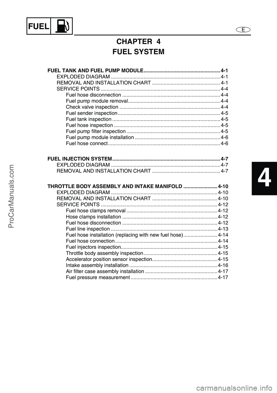
CHAPTER 4
FUEL SYSTEM
FUEL TANK AND FUEL PUMP MODULE...................................................... 4-1
EXPLODED DIAGRAM ............................................................................. 4-1
REMOVAL AND INSTALLATION CHART ................................................ 4-1
SERVICE POINTS .................................................................................... 4-4
Fuel hose disconnection ..................................................................... 4-4
Fuel pump module removal................................................................. 4-4
Check valve inspection ....................................................................... 4-4
Fuel sender inspection ........................................................................ 4-5
Fuel tank inspection ............................................................................ 4-5
Fuel hose inspection ........................................................................... 4-5
Fuel pump filter inspection .................................................................. 4-5
Fuel pump module installation ............................................................ 4-6
Fuel hose connect ............................................................................... 4-6
FUEL INJECTION SYSTEM ............................................................................ 4-7
EXPLODED DIAGRAM ............................................................................. 4-7
REMOVAL AND INSTALLATION CHART ................................................ 4-7
THROTTLE BODY ASSEMBLY AND INTAKE MANIFOLD ........................ 4-10
EXPLODED DIAGRAM ........................................................................... 4-10
REMOVAL AND INSTALLATION CHART .............................................. 4-10
SERVICE POINTS .................................................................................. 4-12
Fuel hose clamps removal ................................................................ 4-12
Hose clamps installation ................................................................... 4-12
Fuel hose disconnection ................................................................... 4-12
Fuel line inspection ........................................................................... 4-13
Fuel hose installation (replacing with new fuel hose) ........................ 4-14
Fuel hose connection ........................................................................ 4-14
Fuel injectors inspection.................................................................... 4-15
Throttle body assembly inspection .................................................... 4-15
Accelerator position sensor inspection.............................................. 4-15
Intake assembly installation .............................................................. 4-16
Air filter case assembly installation ................................................... 4-17
Fuel pressure measurement ............................................................. 4-17
ProCarManuals.com
Page 78 of 347
4-1
EFUELFUEL TANK AND FUEL PUMP MODULE
FUEL TANK AND FUEL PUMP MODULE
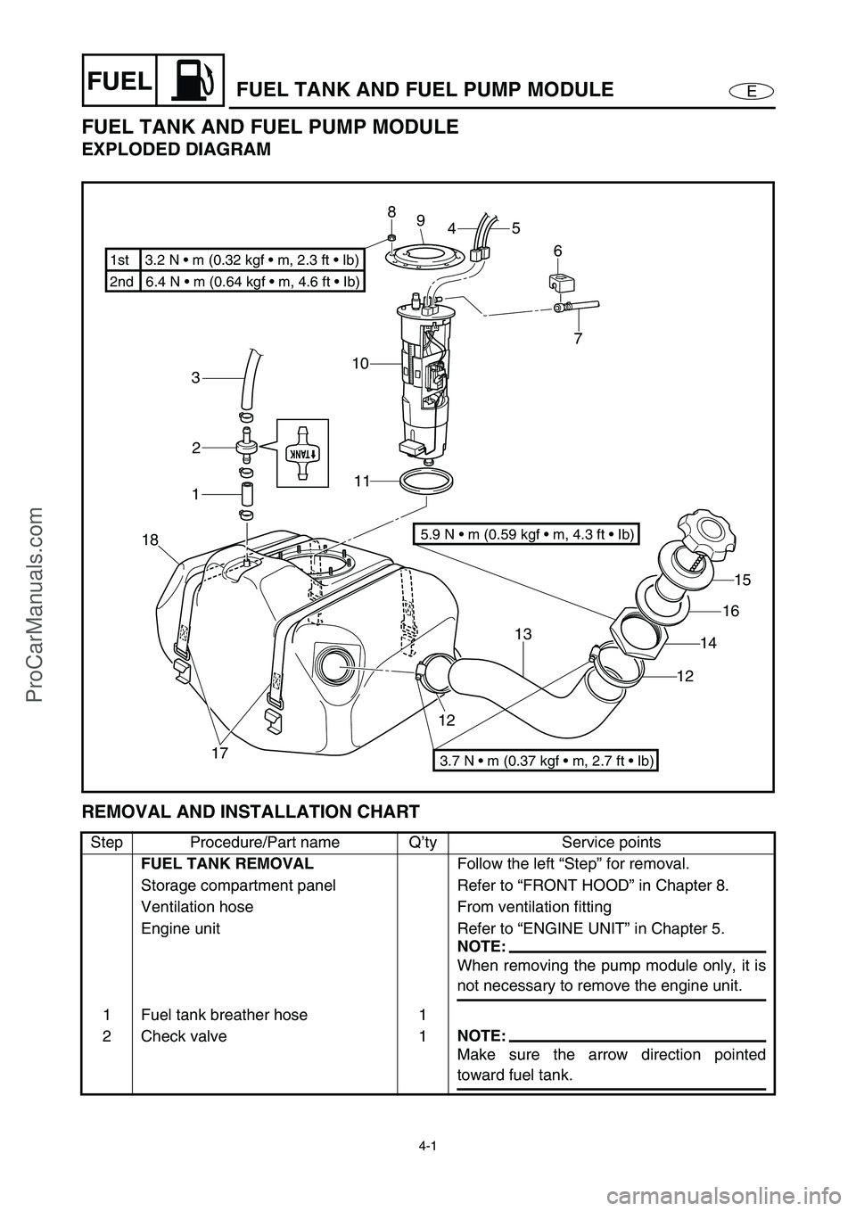
EXPLODED DIAGRAM
REMOVAL AND INSTALLATION CHART
Step Procedure/Part name Q’ty Service points
FUEL TANK REMOVAL
Follow the left “Step” for removal.
Storage compartment panel Refer to “FRONT HOOD” in Chapter 8.
Ventilation hose From ventilation fitting
Engine unit Refer to “ENGINE UNIT” in Chapter 5.
NOTE:
When removing the pump module only, it is
not necessary to remove the engine unit.
1 Fuel tank breather hose 1
2 Check valve 1
NOTE:
Make sure the arrow direction pointed
toward fuel tank.
7
10
11 3
2
1
18
17121315
16
14
12 6 5
4 8
9
2nd 6.4 N • m (0.64 kgf m, 4.6 ft Ib) 1st 3.2 N m (0.32 kgf m, 2.3 ft Ib)
3.7 N m (0.37 kgf m, 2.7 ft Ib)
5.9 N m (0.59 kgf m, 4.3 ft Ib)
ProCarManuals.com
Page 79 of 347
4-2
EFUELFUEL TANK AND FUEL PUMP MODULE
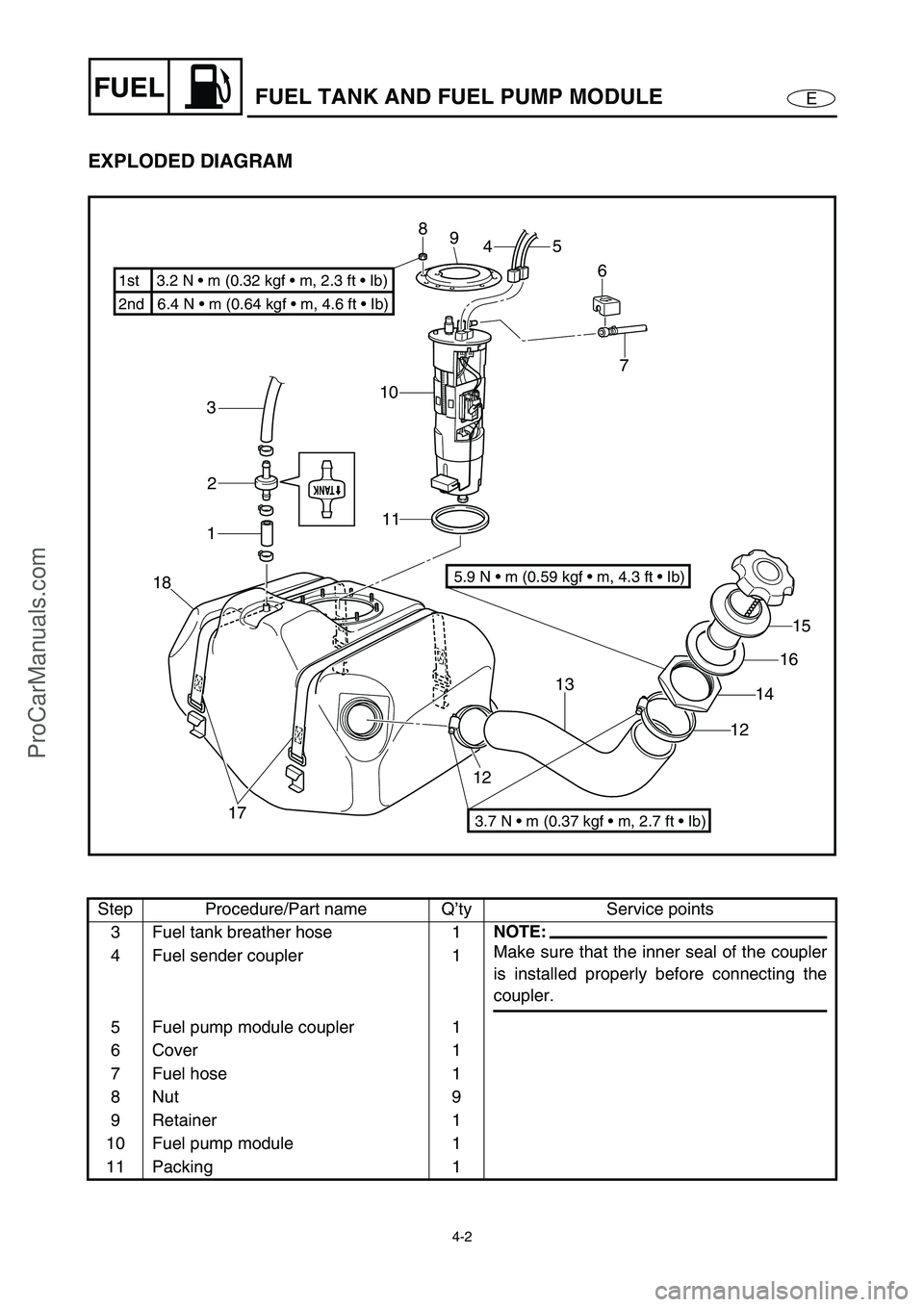
EXPLODED DIAGRAM
Step Procedure/Part name Q’ty Service points
3 Fuel tank breather hose 1
NOTE:
Make sure that the inner seal of the coupler
is installed properly before connecting the
coupler. 4 Fuel sender coupler 1
5 Fuel pump module coupler 1
6 Cover 1
7 Fuel hose 1
8Nut 9
9 Retainer 1
10 Fuel pump module 1
11 Packing 1
7
10
11 3
2
1
18
17121315
16
14
12 6 5
4 8
9
2nd 6.4 N m (0.64 kgf m, 4.6 ft Ib) 1st 3.2 N m (0.32 kgf m, 2.3 ft Ib)
3.7 N m (0.37 kgf m, 2.7 ft Ib)
5.9 N m (0.59 kgf m, 4.3 ft Ib)
ProCarManuals.com
Page 80 of 347
4-3
EFUELFUEL TANK AND FUEL PUMP MODULE
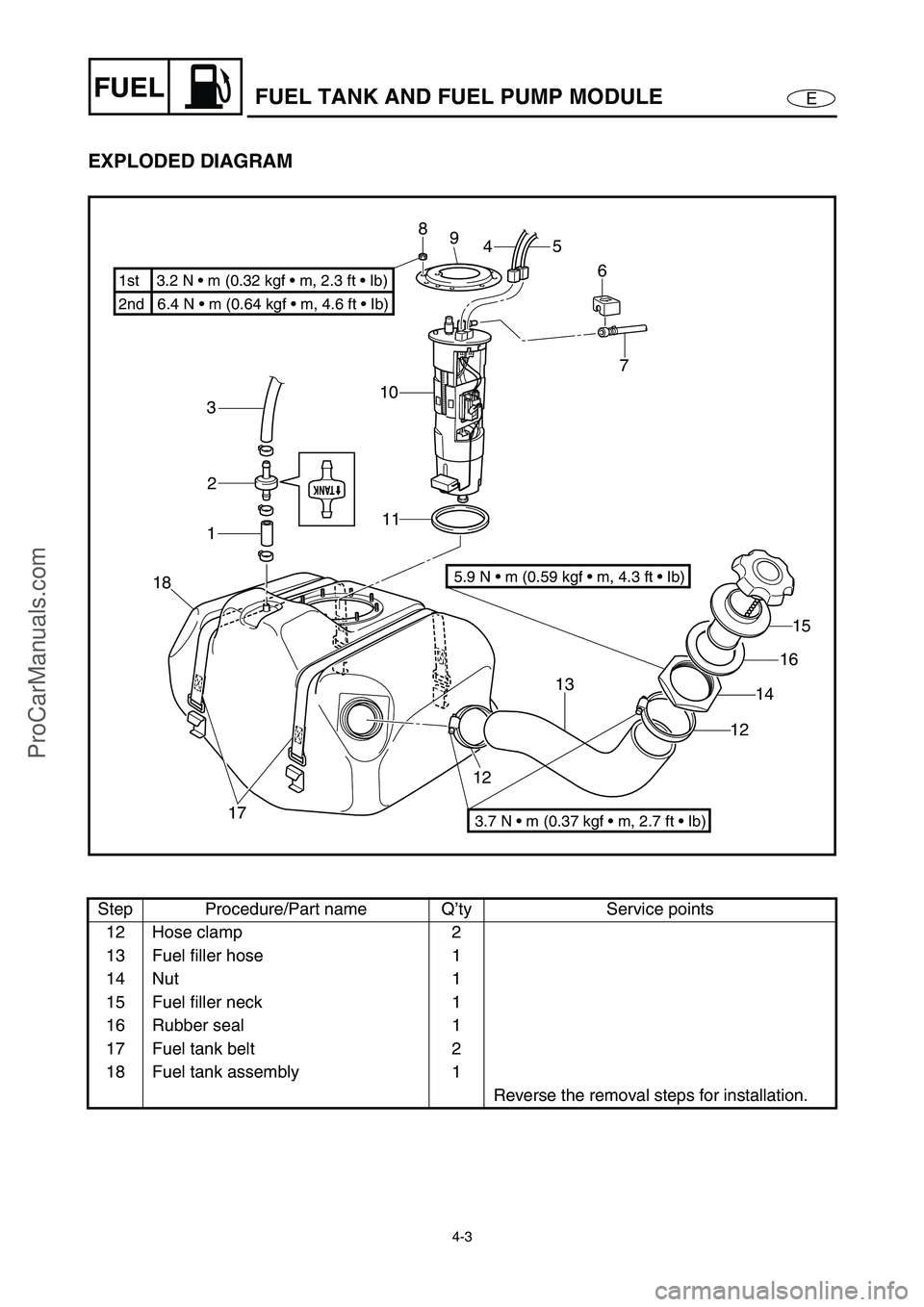
EXPLODED DIAGRAM
Step Procedure/Part name Q’ty Service points
12 Hose clamp 2
13 Fuel filler hose 1
14 Nut 1
15 Fuel filler neck 1
16 Rubber seal 1
17 Fuel tank belt 2
18 Fuel tank assembly 1
Reverse the removal steps for installation.
7
10
11 3
2
1
18
17121315
16
14
12 6 5
4 8
9
2nd 6.4 N m (0.64 kgf m, 4.6 ft Ib) 1st 3.2 N m (0.32 kgf m, 2.3 ft Ib)
3.7 N m (0.37 kgf m, 2.7 ft Ib)
5.9 N m (0.59 kgf m, 4.3 ft Ib)
ProCarManuals.com
Page 84 of 347
4-7
EFUELFUEL INJECTION SYSTEM
FUEL INJECTION SYSTEM
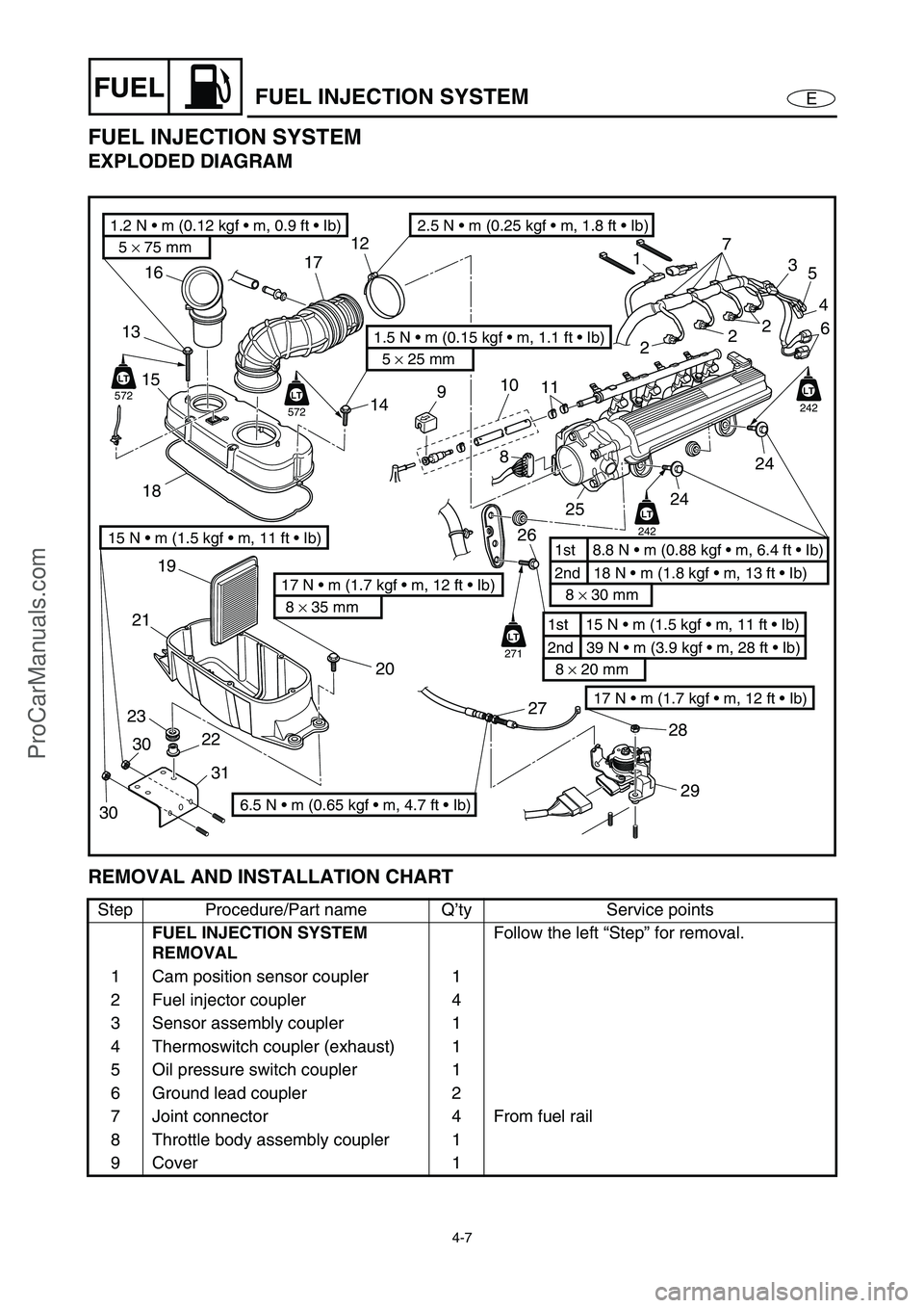
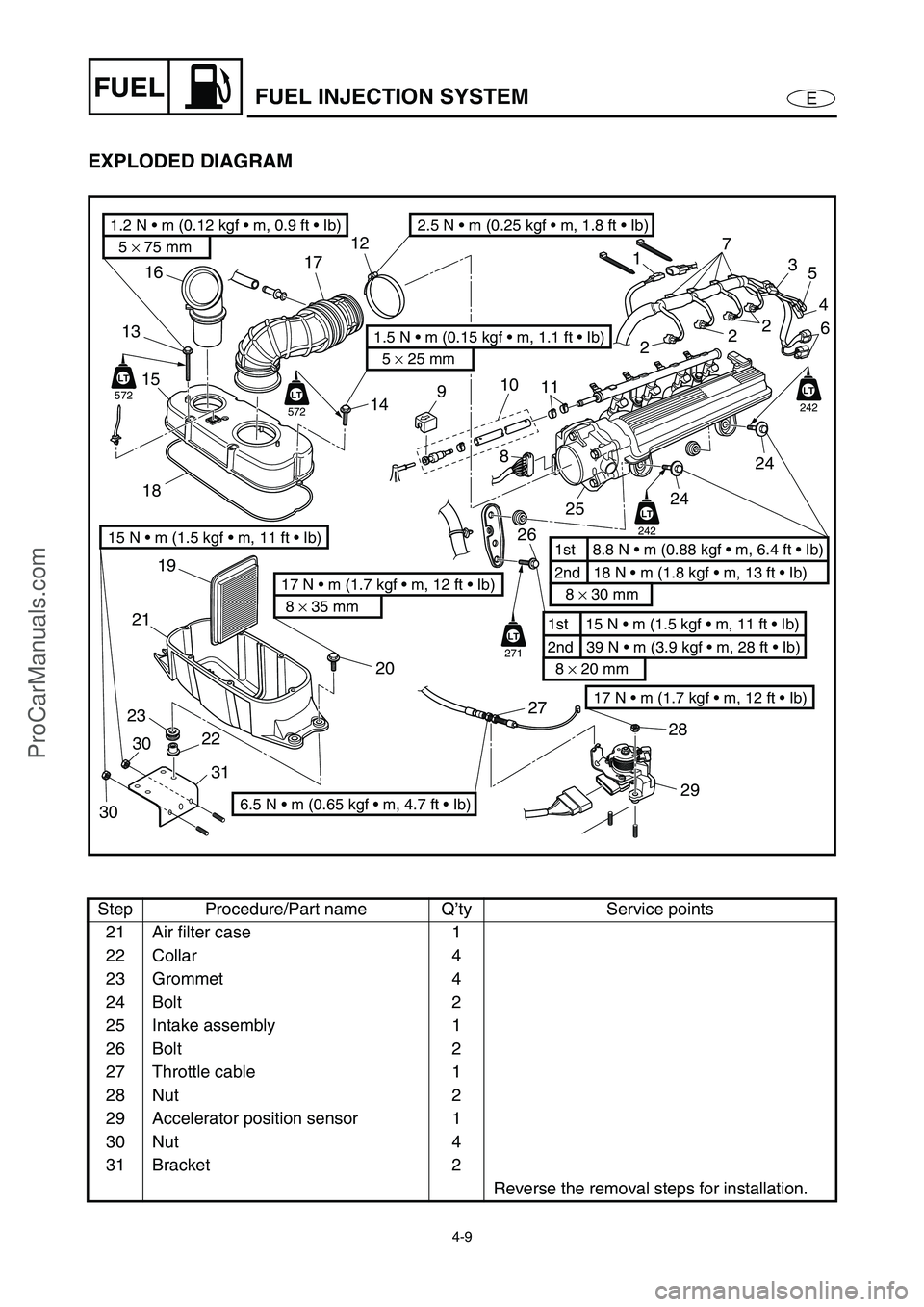
EXPLODED DIAGRAM
REMOVAL AND INSTALLATION CHART
Step Procedure/Part name Q’ty Service points
FUEL INJECTION SYSTEM
REMOVALFollow the left “Step” for removal.
1 Cam position sensor coupler 1
2 Fuel injector coupler 4
3 Sensor assembly coupler 1
4 Thermoswitch coupler (exhaust) 1
5 Oil pressure switch coupler 1
6 Ground lead coupler 2
7 Joint connector 4 From fuel rail
8 Throttle body assembly coupler 1
9 Cover 1
17 N m (1.7 kgf m, 12 ft Ib)
5 × 75 mm
1.2 N m (0.12 kgf m, 0.9 ft Ib)
5 × 25 mm
1.5 N m (0.15 kgf m, 1.1 ft Ib)
8 × 35 mm
17 N m (1.7 kgf m, 12 ft Ib)2nd 18 N m (1.8 kgf m, 13 ft Ib) 1st 8.8 N m (0.88 kgf m, 6.4 ft Ib)
8 × 30 mm
2nd 39 N m (3.9 kgf m, 28 ft Ib) 1st 15 N m (1.5 kgf m, 11 ft Ib)
8 × 20 mm
LT
242
LT
242
LT
271
LT
572
LT
LT
572
LT
22 2320 19
2118 15 1316
14 1712
17
3
2
2
25
4
6
24
24
25 8
26
27
28
29
11 10
9
2.5 N m (0.25 kgf m, 1.8 ft Ib)
6.5 N m (0.65 kgf m, 4.7 ft Ib)
15 N m (1.5 kgf m, 11 ft Ib)
3031
30
ProCarManuals.com
Page 85 of 347
4-8
EFUELFUEL INJECTION SYSTEM
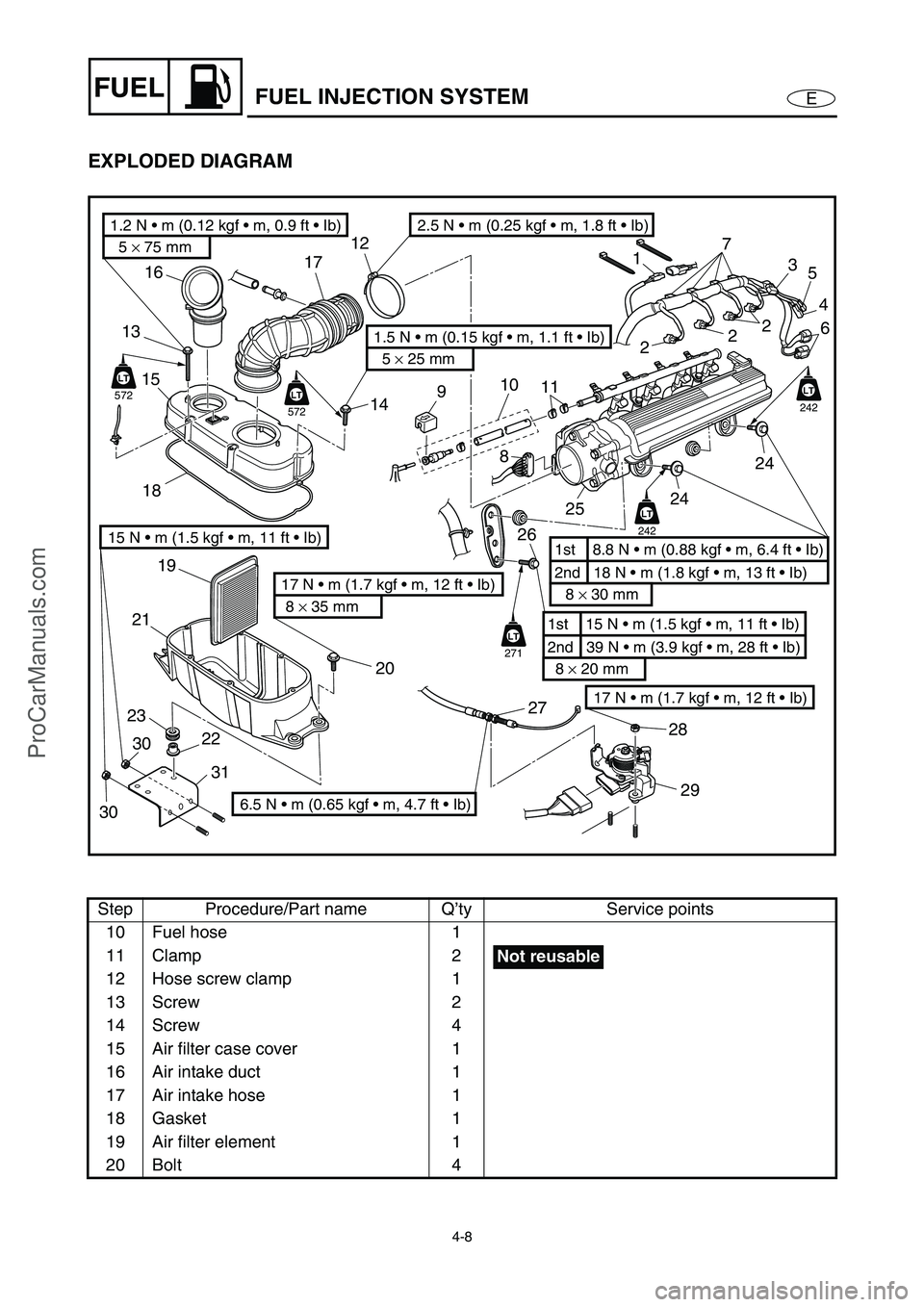
EXPLODED DIAGRAM
Step Procedure/Part name Q’ty Service points
10 Fuel hose 1
11 Clamp 2
12 Hose screw clamp 1
13 Screw 2
14 Screw 4
15 Air filter case cover 1
16 Air intake duct 1
17 Air intake hose 1
18 Gasket 1
19 Air filter element 1
20 Bolt 4
17 N m (1.7 kgf m, 12 ft Ib)
5 × 75 mm
1.2 N m (0.12 kgf m, 0.9 ft Ib)
5 × 25 mm
1.5 N m (0.15 kgf m, 1.1 ft Ib)
8 × 35 mm
17 N m (1.7 kgf m, 12 ft Ib)2nd 18 N m (1.8 kgf m, 13 ft Ib) 1st 8.8 N m (0.88 kgf m, 6.4 ft Ib)
8 × 30 mm
2nd 39 N m (3.9 kgf m, 28 ft Ib) 1st 15 N m (1.5 kgf m, 11 ft Ib)
8 × 20 mm
LT
242
LT
242
LT
271
LT
572
LT
LT
572
LT
22 2320 19
2118 15 1316
14 1712
17
3
2
2
25
4
6
24
24
25 8
26
27
28
29
11 10
9
2.5 N m (0.25 kgf m, 1.8 ft Ib)
6.5 N m (0.65 kgf m, 4.7 ft Ib)
15 N m (1.5 kgf m, 11 ft Ib)
3031
30
Not reusable
ProCarManuals.com
Page 86 of 347
4-9
EFUELFUEL INJECTION SYSTEM
EXPLODED DIAGRAM
Step Procedure/Part name Q’ty Service points
21 Air filter case 1
22 Collar 4
23 Grommet 4
24 Bolt 2
25 Intake assembly 1
26 Bolt 2
27 Throttle cable 1
28 Nut 2
29 Accelerator position sensor 1
30 Nut 4
31 Bracket 2
Reverse the removal steps for installation.
17 N m (1.7 kgf m, 12 ft Ib)
5 × 75 mm
1.2 N m (0.12 kgf m, 0.9 ft Ib)
5 × 25 mm
1.5 N m (0.15 kgf m, 1.1 ft Ib)
8 × 35 mm
17 N m (1.7 kgf m, 12 ft Ib)2nd 18 N m (1.8 kgf m, 13 ft Ib) 1st 8.8 N m (0.88 kgf m, 6.4 ft Ib)
8 × 30 mm
2nd 39 N m (3.9 kgf m, 28 ft Ib) 1st 15 N m (1.5 kgf m, 11 ft Ib)
8 × 20 mm
LT
242
LT
242
LT
271
LT
572
LT
LT
572
LT
22 2320 19
2118 15 1316
14 1712
17
3
2
2
25
4
6
24
24
25 8
26
27
28
29
11 10
9
2.5 N m (0.25 kgf m, 1.8 ft Ib)
6.5 N m (0.65 kgf m, 4.7 ft Ib)
15 N m (1.5 kgf m, 11 ft Ib)
3031
30
ProCarManuals.com
Page 87 of 347
4-10
EFUEL
THROTTLE BODY ASSEMBLY AND INTAKE
MANIFOLD
THROTTLE BODY ASSEMBLY AND INTAKE MANIFOLD
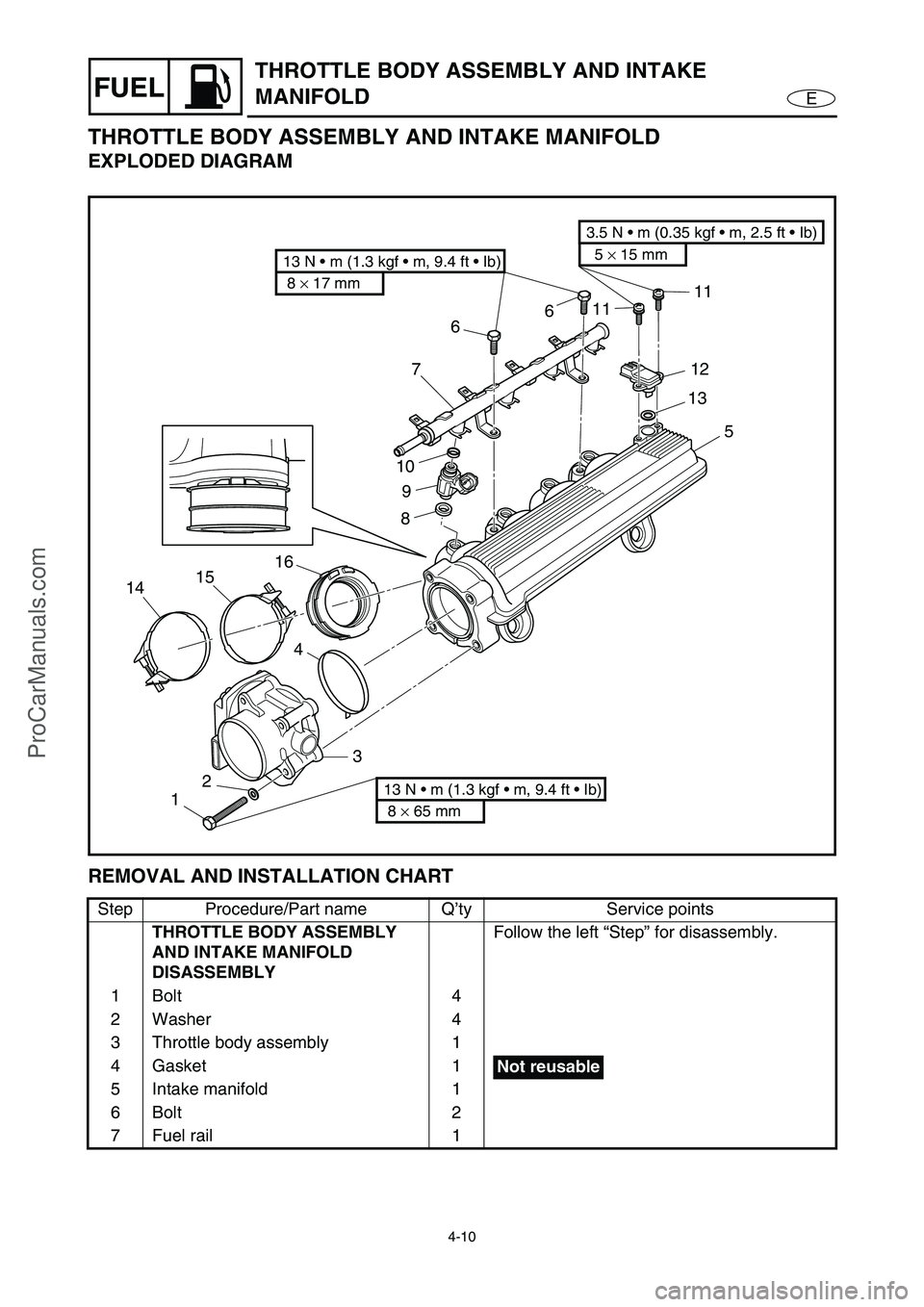
EXPLODED DIAGRAM
REMOVAL AND INSTALLATION CHART
Step Procedure/Part name Q’ty Service points
THROTTLE BODY ASSEMBLY
AND INTAKE MANIFOLD
DISASSEMBLYFollow the left “Step” for disassembly.
1Bolt 4
2 Washer 4
3 Throttle body assembly 1
4Gasket 1
5 Intake manifold 1
6Bolt 2
7 Fuel rail 1
8 × 17 mm
13 N m (1.3 kgf m, 9.4 ft Ib)5 × 15 mm
3.5 N m (0.35 kgf m, 2.5 ft Ib)
8 × 65 mm
13 N m (1.3 kgf m, 9.4 ft Ib)123 4 14151689 107661111
12
13
5
Not reusable
ProCarManuals.com