diagram YAMAHA VX110 2005 User Guide
[x] Cancel search | Manufacturer: YAMAHA, Model Year: 2005, Model line: VX110, Model: YAMAHA VX110 2005Pages: 347, PDF Size: 14.17 MB
Page 88 of 347

4-11
EFUEL
THROTTLE BODY ASSEMBLY AND INTAKE
MANIFOLD
EXPLODED DIAGRAM
Step Procedure/Part name Q’ty Service points
8Gasket 4
9 Fuel injector 4
10 O-ring 4
11 Screw 2
12 Sensor assembly 1
13 O-ring 1
14 Clamp 4
15 Clamp 4
16 Intake manifold joint 4
Reverse the disassembly steps for
assembly.
8 × 17 mm
13 N m (1.3 kgf m, 9.4 ft Ib)5 × 15 mm
3.5 N m (0.35 kgf m, 2.5 ft Ib)
8 × 65 mm
13 N m (1.3 kgf m, 9.4 ft Ib)123 4 14151689 107661111
12
13
5
Not reusable
Not reusable
Not reusable
ProCarManuals.com
Page 97 of 347
EPOWR
1
2
3
4
5
6
7
8
9
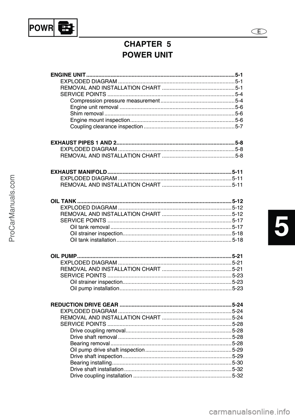
CHAPTER 5
POWER UNIT
ENGINE UNIT .................................................................................................. 5-1
EXPLODED DIAGRAM ............................................................................. 5-1
REMOVAL AND INSTALLATION CHART ................................................ 5-1
SERVICE POINTS .................................................................................... 5-4
Compression pressure measurement ................................................. 5-4
Engine unit removal ............................................................................ 5-6
Shim removal ...................................................................................... 5-6
Engine mount inspection ..................................................................... 5-6
Coupling clearance inspection ............................................................ 5-7
EXHAUST PIPES 1 AND 2.............................................................................. 5-8
EXPLODED DIAGRAM ............................................................................. 5-8
REMOVAL AND INSTALLATION CHART ................................................ 5-8
EXHAUST MANIFOLD .................................................................................. 5-11
EXPLODED DIAGRAM ........................................................................... 5-11
REMOVAL AND INSTALLATION CHART .............................................. 5-11
OIL TANK ...................................................................................................... 5-12
EXPLODED DIAGRAM ........................................................................... 5-12
REMOVAL AND INSTALLATION CHART .............................................. 5-12
SERVICE POINTS .................................................................................. 5-17
Oil tank removal ................................................................................ 5-17
Oil strainer inspection........................................................................ 5-18
Oil tank installation ............................................................................ 5-18
OIL PUMP ...................................................................................................... 5-21
EXPLODED DIAGRAM ........................................................................... 5-21
REMOVAL AND INSTALLATION CHART .............................................. 5-21
SERVICE POINTS .................................................................................. 5-23
Oil strainer inspection........................................................................ 5-23
Oil pump installation .......................................................................... 5-23
REDUCTION DRIVE GEAR .......................................................................... 5-24
EXPLODED DIAGRAM ........................................................................... 5-24
REMOVAL AND INSTALLATION CHART .............................................. 5-24
SERVICE POINTS .................................................................................. 5-28
Drive coupling removal...................................................................... 5-28
Drive shaft removal ........................................................................... 5-28
Bearing removal ................................................................................ 5-28
Oil pump drive shaft inspection ......................................................... 5-29
Drive shaft inspection ........................................................................ 5-29
Bearing installing ............................................................................... 5-30
Drive shaft installation ....................................................................... 5-32
Drive coupling installation ................................................................. 5-32
ProCarManuals.com
Page 98 of 347
EPOWR
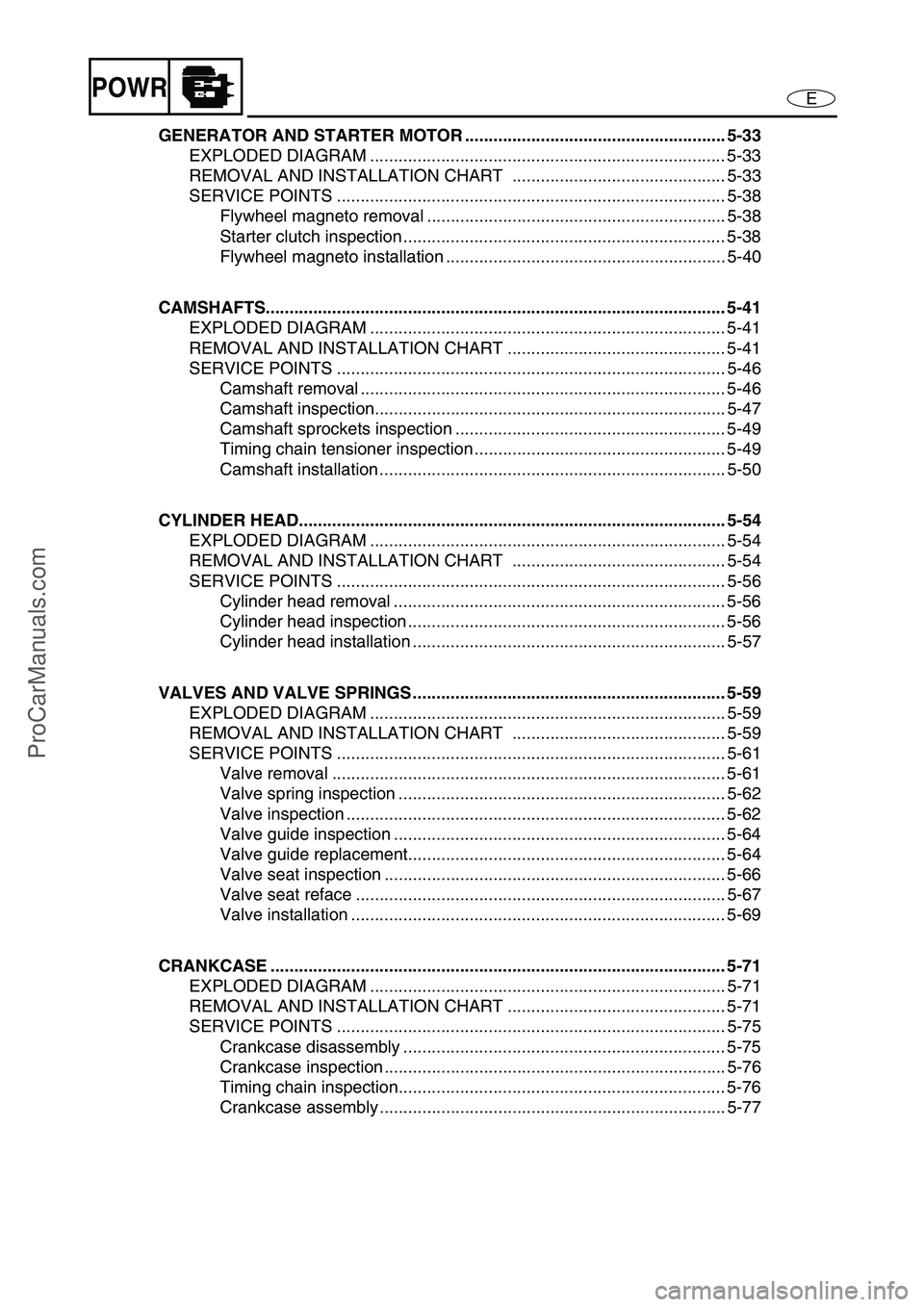
GENERATOR AND STARTER MOTOR ....................................................... 5-33
EXPLODED DIAGRAM ........................................................................... 5-33
REMOVAL AND INSTALLATION CHART ............................................. 5-33
SERVICE POINTS .................................................................................. 5-38
Flywheel magneto removal ............................................................... 5-38
Starter clutch inspection .................................................................... 5-38
Flywheel magneto installation ........................................................... 5-40
CAMSHAFTS................................................................................................. 5-41
EXPLODED DIAGRAM ........................................................................... 5-41
REMOVAL AND INSTALLATION CHART .............................................. 5-41
SERVICE POINTS .................................................................................. 5-46
Camshaft removal ............................................................................. 5-46
Camshaft inspection.......................................................................... 5-47
Camshaft sprockets inspection ......................................................... 5-49
Timing chain tensioner inspection ..................................................... 5-49
Camshaft installation ......................................................................... 5-50
CYLINDER HEAD.......................................................................................... 5-54
EXPLODED DIAGRAM ........................................................................... 5-54
REMOVAL AND INSTALLATION CHART ............................................. 5-54
SERVICE POINTS .................................................................................. 5-56
Cylinder head removal ...................................................................... 5-56
Cylinder head inspection ................................................................... 5-56
Cylinder head installation .................................................................. 5-57
VALVES AND VALVE SPRINGS .................................................................. 5-59
EXPLODED DIAGRAM ........................................................................... 5-59
REMOVAL AND INSTALLATION CHART ............................................. 5-59
SERVICE POINTS .................................................................................. 5-61
Valve removal ................................................................................... 5-61
Valve spring inspection ..................................................................... 5-62
Valve inspection ................................................................................ 5-62
Valve guide inspection ...................................................................... 5-64
Valve guide replacement................................................................... 5-64
Valve seat inspection ........................................................................ 5-66
Valve seat reface .............................................................................. 5-67
Valve installation ............................................................................... 5-69
CRANKCASE ................................................................................................ 5-71
EXPLODED DIAGRAM ........................................................................... 5-71
REMOVAL AND INSTALLATION CHART .............................................. 5-71
SERVICE POINTS .................................................................................. 5-75
Crankcase disassembly .................................................................... 5-75
Crankcase inspection ........................................................................ 5-76
Timing chain inspection..................................................................... 5-76
Crankcase assembly ......................................................................... 5-77
ProCarManuals.com
Page 99 of 347
EPOWR
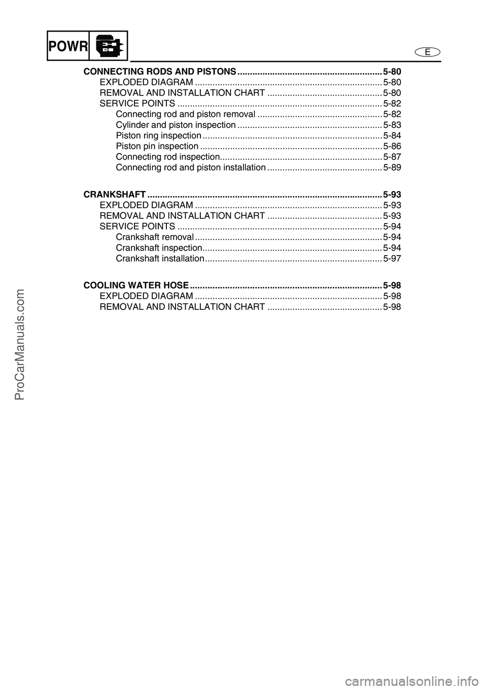
CONNECTING RODS AND PISTONS .......................................................... 5-80
EXPLODED DIAGRAM ........................................................................... 5-80
REMOVAL AND INSTALLATION CHART .............................................. 5-80
SERVICE POINTS .................................................................................. 5-82
Connecting rod and piston removal .................................................. 5-82
Cylinder and piston inspection .......................................................... 5-83
Piston ring inspection ........................................................................ 5-84
Piston pin inspection ......................................................................... 5-86
Connecting rod inspection................................................................. 5-87
Connecting rod and piston installation .............................................. 5-89
CRANKSHAFT .............................................................................................. 5-93
EXPLODED DIAGRAM ........................................................................... 5-93
REMOVAL AND INSTALLATION CHART .............................................. 5-93
SERVICE POINTS .................................................................................. 5-94
Crankshaft removal ........................................................................... 5-94
Crankshaft inspection........................................................................ 5-94
Crankshaft installation ....................................................................... 5-97
COOLING WATER HOSE ............................................................................. 5-98
EXPLODED DIAGRAM ........................................................................... 5-98
REMOVAL AND INSTALLATION CHART .............................................. 5-98
ProCarManuals.com
Page 100 of 347
5-1
EPOWRENGINE UNIT
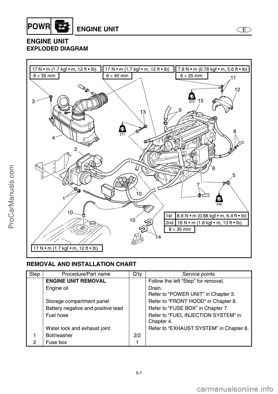
ENGINE UNIT
EXPLODED DIAGRAM
REMOVAL AND INSTALLATION CHART
Step Procedure/Part name Q’ty Service points
ENGINE UNIT REMOVAL
Follow the left “Step” for removal.
Engine oil Drain.
Refer to “POWER UNIT” in Chapter 3.
Storage compartment panel Refer to “FRONT HOOD” in Chapter 8.
Battery negative and positive lead Refer to “FUSE BOX” in Chapter 7.
Fuel hose Refer to “FUEL INJECTION SYSTEM” in
Chapter 4.
Water lock and exhaust joint Refer to “EXHAUST SYSTEM” in Chapter 8.
1 Bolt/washer 2/2
2 Fuse box 1
14 10
10
2
113
3
4
11
15
12
8
7
9
6
5
2nd 18 N m (1.8 kgf m, 13 ft Ib) 1st 8.8 N m (0.88 kgf m, 6.4 ft Ib)
8 × 35 mm
6 × 25 mm
7.8 N m (0.78 kgf m, 5.6 ft Ib)
8 × 35 mm 17 N m (1.7 kgf m, 12 ft Ib)
17 N m (1.7 kgf m, 12 ft Ib)8 × 40 mm
17 N m (1.7 kgf m, 12 ft Ib)
10LT
242
LT
LT
572
LT
LT
271
ProCarManuals.com
Page 101 of 347
5-2
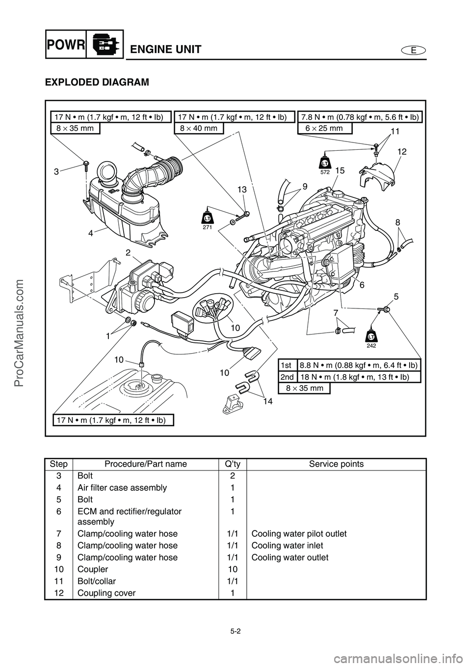
EPOWRENGINE UNIT
EXPLODED DIAGRAM
Step Procedure/Part name Q’ty Service points
3Bolt 2
4 Air filter case assembly 1
5Bolt 1
6 ECM and rectifier/regulator
assembly1
7 Clamp/cooling water hose 1/1 Cooling water pilot outlet
8 Clamp/cooling water hose 1/1 Cooling water inlet
9 Clamp/cooling water hose 1/1 Cooling water outlet
10 Coupler 10
11 Bolt/collar 1/1
12 Coupling cover 1
14 10
10
2
113
3
4
11
15
12
8
7
9
6
5
2nd 18 N m (1.8 kgf m, 13 ft Ib) 1st 8.8 N m (0.88 kgf m, 6.4 ft Ib)
8 × 35 mm
6 × 25 mm
7.8 N m (0.78 kgf m, 5.6 ft Ib)
8 × 35 mm 17 N m (1.7 kgf m, 12 ft Ib)
17 N m (1.7 kgf m, 12 ft Ib)8 × 40 mm
17 N m (1.7 kgf m, 12 ft Ib)
10LT
242
LT
LT
572
LT
LT
271
ProCarManuals.com
Page 102 of 347
5-3
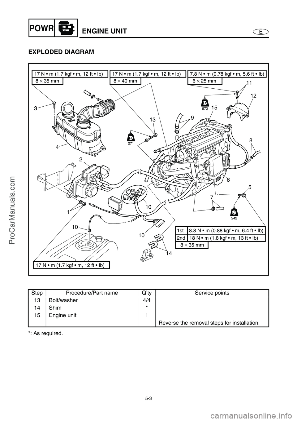
EPOWRENGINE UNIT
EXPLODED DIAGRAM
*: As required.Step Procedure/Part name Q’ty Service points
13 Bolt/washer 4/4
14 Shim *
15 Engine unit 1
Reverse the removal steps for installation.
14 10
10
2
113
3
4
11
15
12
8
7
9
6
5
2nd 18 N m (1.8 kgf m, 13 ft Ib) 1st 8.8 N m (0.88 kgf m, 6.4 ft Ib)
8 × 35 mm
6 × 25 mm
7.8 N m (0.78 kgf m, 5.6 ft Ib)
8 × 35 mm 17 N m (1.7 kgf m, 12 ft Ib)
17 N m (1.7 kgf m, 12 ft Ib)8 × 40 mm
17 N m (1.7 kgf m, 12 ft Ib)
10LT
242
LT
LT
572
LT
LT
271
ProCarManuals.com
Page 107 of 347

5-8
EPOWREXHAUST PIPES 1 AND 2
EXHAUST PIPES 1 AND 2
EXPLODED DIAGRAM
REMOVAL AND INSTALLATION CHART
Step Procedure/Part name Q’ty Service points
EXHAUST PIPES 1 AND 2
REMOVALFollow the left “Step” for removal.
Engine unit Refer to “ENGINE UNIT”.
È
For cooling water pilot outlet on port side
É
From water jacket
1 Clamp/cooling water hose 1/1
2 Clamp/cooling water hose 1/1
3Bolt 2
4 Thermoswitch (exhaust) 1
5 Exhaust joint clamp 2 Slide the outer exhaust joint for exhaust
manifold side
6 Exhaust joint clamp 2
6
64 3
É
5
2
È 6 × 16 mm
7.6 N m (0.76 kgf m, 5.5 ft Ib)
2nd 3.4 N m (0.34 kgf m, 2.5 ft Ib) 1st 3.4 N m (0.34 kgf m, 2.5 ft Ib)LT
242
LT
242
LT
572
LT
LT
572
LT
LT
242
1
LT
242
LT
242
ProCarManuals.com
Page 108 of 347
5-9
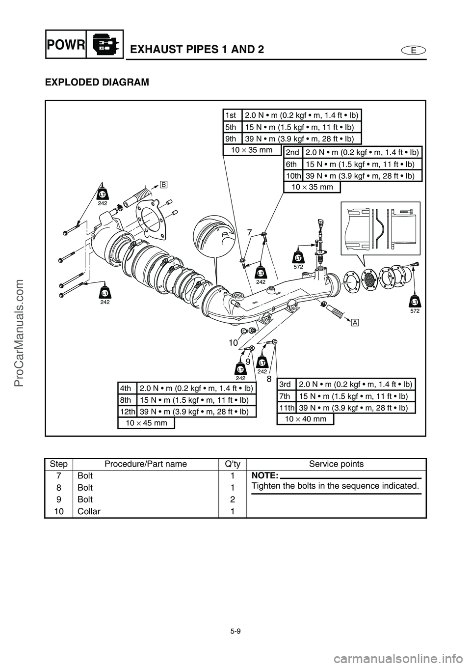
EPOWREXHAUST PIPES 1 AND 2
EXPLODED DIAGRAM
Step Procedure/Part name Q’ty Service points
7Bolt 1
NOTE:
Tighten the bolts in the sequence indicated.
8Bolt 1
9Bolt 2
10 Collar 1
7
10
9
8
É
È
6th 15 N m (1.5 kgf m, 11 ft Ib) 2nd 2.0 N m (0.2 kgf m, 1.4 ft Ib)
10th 39 N m (3.9 kgf m, 28 ft Ib)
10 × 35 mm
5th 15 N m (1.5 kgf m, 11 ft Ib) 1st 2.0 N m (0.2 kgf m, 1.4 ft Ib)
9th 39 N m (3.9 kgf m, 28 ft Ib)
10 × 35 mm
8th 15 N m (1.5 kgf m, 11 ft Ib) 4th 2.0 N m (0.2 kgf m, 1.4 ft Ib)
12th 39 N m (3.9 kgf m, 28 ft Ib)
10 × 45 mm
7th 15 N m (1.5 kgf m, 11 ft Ib) 3rd 2.0 N m (0.2 kgf m, 1.4 ft Ib)
11th 39 N m (3.9 kgf m, 28 ft Ib)
10 × 40 mm
LT
242
LT
242
LT
572
LT
LT
572
LT
LT
242
LT
242
LT
242
ProCarManuals.com
Page 109 of 347
5-10
EPOWR
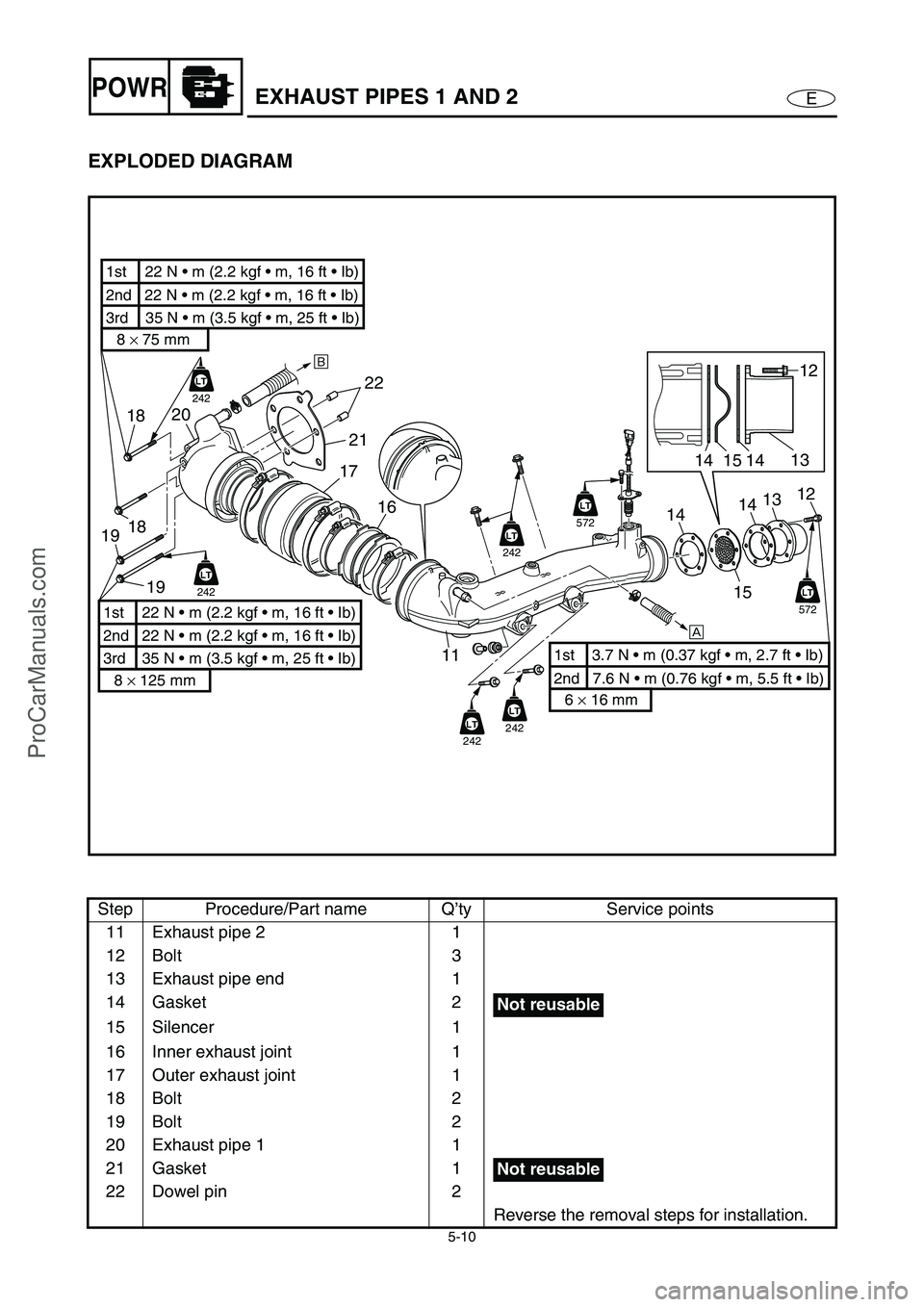
EXPLODED DIAGRAM
Step Procedure/Part name Q’ty Service points
11 Exhaust pipe 2 1
12 Bolt 3
13 Exhaust pipe end 1
14 Gasket 2
15 Silencer 1
16 Inner exhaust joint 1
17 Outer exhaust joint 1
18 Bolt 2
19 Bolt 2
20 Exhaust pipe 1 1
21 Gasket 1
22 Dowel pin 2
Reverse the removal steps for installation.
1417 20
16
1112
13
14
É
18
19
È
22
21
2nd 22 N • m (2.2 kgf m, 16 ft Ib) 1st
22 N m (2.2 kgf m, 16 ft Ib)
3rd 35 N m (3.5 kgf m, 25 ft Ib)
8 × 75 mm
2nd 22 N m (2.2 kgf m, 16 ft Ib) 1st 22 N m (2.2 kgf m, 16 ft Ib)
3rd 35 N m (3.5 kgf m, 25 ft Ib)
8 × 125 mm
2nd 7.6 N m (0.76 kgf m, 5.5 ft Ib)
1st 3.7 N m (0.37 kgf m, 2.7 ft Ib)
6 × 16 mm
LT
242
19
18
LT
242
LT
572
LT
LT
572
LT
LT
242
LT
242
LT
242
12
13
15
14
14
15
Not reusable
Not reusable
EXHAUST PIPES 1 AND 2
ProCarManuals.com