electrical YAMAHA VX110 2005 Service Manual
[x] Cancel search | Manufacturer: YAMAHA, Model Year: 2005, Model line: VX110, Model: YAMAHA VX110 2005Pages: 347, PDF Size: 14.17 MB
Page 2 of 347
E
NOTICE
This manual has been prepared by Yamaha primarily for use by Yamaha dealers and their trained
mechanics when performing maintenance procedures and repairs to Yamaha equipment. It has
been written to suit the needs of persons who have a basic understanding of the mechanical and
electrical concepts and procedures inherent in the work, for without such knowledge attempted
repairs or service to the equipment could render it unsafe or unfit for use.
Because Yamaha has a policy of continuously improving its products, models may differ in detail
from the descriptions and illustrations given in this publication. Use only the latest edition of this
manual. Authorized Yamaha dealers are notified periodically of modifications and significant
changes in specifications and procedures, and these are incorporated in successive editions of this
manual.
A10001-0*
WaveRunner
VX110 Sport, VX110 Deluxe
SERVICE MANUAL
©2005 by Yamaha Motor Corporation, USA
1st Edition, January 2005
All rights reserved.
Any reprinting or unauthorized use
without the written permission of
Yamaha Motor Corporation, USA
is expressly prohibited.
Printed in USA
LIT-18616-02-91
ProCarManuals.com
Page 6 of 347
E
A50001-1-4
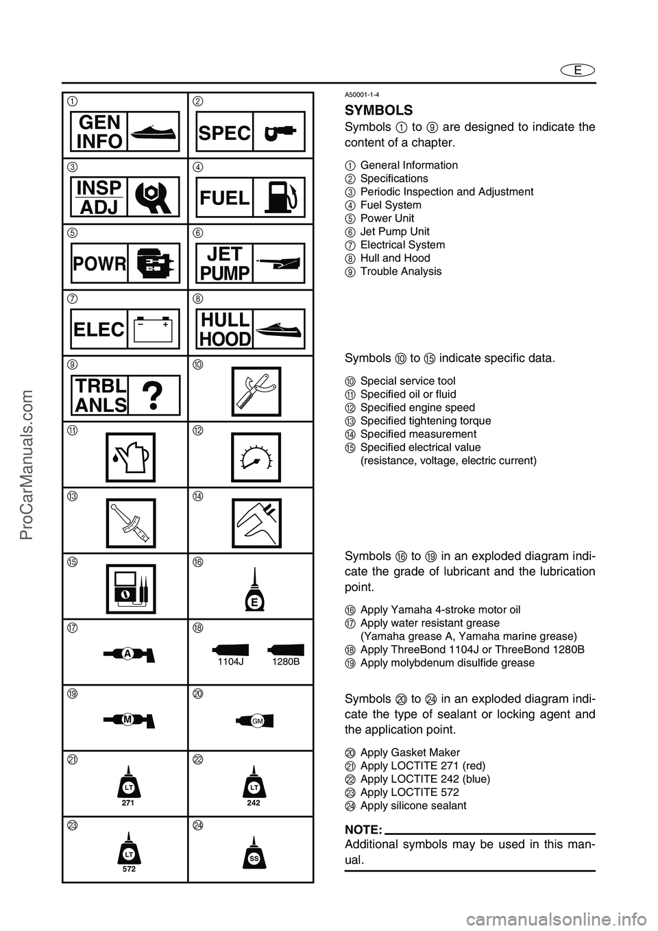
SYMBOLS
Symbols 1 to 9 are designed to indicate the
content of a chapter.
1General Information
2Specifications
3Periodic Inspection and Adjustment
4Fuel System
5Power Unit
6Jet Pump Unit
7Electrical System
8Hull and Hood
9Trouble Analysis
Symbols 0 to E indicate specific data.
0Special service tool
ASpecified oil or fluid
BSpecified engine speed
CSpecified tightening torque
DSpecified measurement
ESpecified electrical value
(resistance, voltage, electric current)
Symbols F to I in an exploded diagram indi-
cate the grade of lubricant and the lubrication
point.
FApply Yamaha 4-stroke motor oil
GApply water resistant grease
(Yamaha grease A, Yamaha marine grease)
HApply ThreeBond 1104J or ThreeBond 1280B
IApply molybdenum disulfide grease
Symbols J to N in an exploded diagram indi-
cate the type of sealant or locking agent and
the application point.
JApply Gasket Maker
KApply LOCTITE 271 (red)
LApply LOCTITE 242 (blue)
MApply LOCTITE 572
NApply silicone sealant
NOTE:
Additional symbols may be used in this man-
ual.
12
34
56
78
90
AB
CD
EF
GH
IJ
KL
MN
GEN
INFOSPEC
INSP
ADJFUEL
POWRJET
PUMP
–+ELECHULL
HOOD
TRBL
ANLS
T R..
E
A1280B1104J
MGM
271
LT
242
LT
572
LTSS
ProCarManuals.com
Page 7 of 347
E
INDEX
GENERAL INFORMATION1GEN
INFO
SPECIFICATIONS2SPEC
PERIODIC INSPECTION AND
ADJUSTMENT
3INSP
ADJ
FUEL SYSTEM4FUEL
POWER UNIT5POWR
JET PUMP UNIT6JET
PUMP
ELECTRICAL SYSTEM7ELEC
HULL AND HOOD8HULL
HOOD
TROUBLE ANALYSIS9TRBL
ANLS
–+
A30000-0
ProCarManuals.com
Page 21 of 347

ESPEC
1
2
3
4
5
6
7
8
9
CHAPTER 2
SPECIFICATIONS
GENERAL SPECIFICATIONS ....................................................................... 2-1
MAINTENANCE SPECIFICATIONS ............................................................... 2-3
ENGINE .................................................................................................... 2-3
JET PUMP UNIT ...................................................................................... 2-6
HULL AND HOOD .................................................................................... 2-6
ELECTRICAL ............................................................................................ 2-7
TIGHTENING TORQUES .............................................................................. 2-10
SPECIFIED TORQUES ........................................................................... 2-10
GENERAL TORQUE ............................................................................... 2-15
CABLE AND HOSE ROUTING ..................................................................... 2-16
ProCarManuals.com
Page 27 of 347
2-6
ESPECMAINTENANCE SPECIFICATIONS
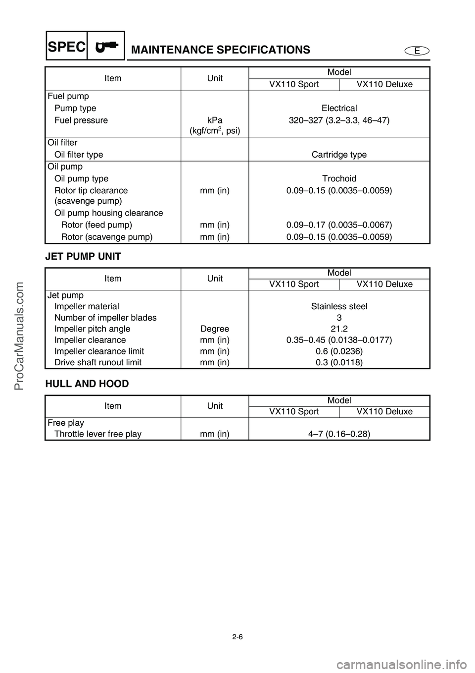
JET PUMP UNIT
HULL AND HOOD
Fuel pump
Pump type Electrical
Fuel pressure kPa
(kgf/cm
2, psi)320–327 (3.2–3.3, 46–47)
Oil filter
Oil filter type Cartridge type
Oil pump
Oil pump type Trochoid
Rotor tip clearance
(scavenge pump)mm (in) 0.09–0.15 (0.0035–0.0059)
Oil pump housing clearance
Rotor (feed pump) mm (in) 0.09–0.17 (0.0035–0.0067)
Rotor (scavenge pump) mm (in) 0.09–0.15 (0.0035–0.0059)
Item UnitModel
VX110 Sport VX110 Deluxe
Jet pump
Impeller material Stainless steel
Number of impeller blades 3
Impeller pitch angle Degree 21.2
Impeller clearance mm (in) 0.35–0.45 (0.0138–0.0177)
Impeller clearance limit mm (in) 0.6 (0.0236)
Drive shaft runout limit mm (in) 0.3 (0.0118)
Item UnitModel
VX110 Sport VX110 Deluxe
Free play
Throttle lever free play mm (in) 4–7 (0.16–0.28) Item UnitModel
VX110 Sport VX110 Deluxe
ProCarManuals.com
Page 28 of 347

2-7
ESPECMAINTENANCE SPECIFICATIONS
ELECTRICAL
Item UnitModel
VX110 Sport VX110 Deluxe
Battery
Type Fluid
Capacity V/Ah 12/19
Specific gravity 1.28
ECM unit
(B/R – R/Y, B/W – R/Y,
B/Y – R/Y, B/G – R/Y)
Output peak voltage lower limit
@cranking (loaded) V 90
@2,000 r/min (loaded) V 130
@3,500 r/min (loaded) V 140
Stator
Pickup coil (W/B – B/O)
Output peak voltage
@cranking (unloaded) V 8.0
@cranking (loaded) V 6.9
@2,000 r/min (loaded) V 19.4
@3,500 r/min (loaded) V 25.1
Lighting coil (G – G)
Output peak voltage
@cranking (unloaded) V 7.8
@2,000 r/min (unloaded) V 24.5
@3,500 r/min (unloaded) V 41.6
Pickup coil resistance
(W/B – B/O)Ω
(color) 459–561
Lighting coil resistance (G – G)Ω
(color) 0.23–0.29
Minimum charging current A @ r/min 14 @ 6,000
Ignition coil
Primary coil resistance
@20 °C (68 °F)Ω
1.19–1.61
Secondary coil resistance
@20 °C (68 °F) kΩ
8.5–11.5
Rectifier/regulator (R – B)
Output peak voltage
@3,500 r/min (unloaded) V 13.0
ProCarManuals.com
Page 36 of 347

2-15
ESPECTIGHTENING TORQUES
Electrical
Fuse box Nut—2 17 1.7 12 7-2
Fuse box bracket Nut—4 15 1.5 11 7-2
ECM Bolt M6 4 4.0 0.4 2.9
572LT7-7
Bracket1st
Bolt M8 28.80.886.4
572LT7-7
2nd 18 1.8 13
Slant detection switchTapping
screwø6 2 3.90.392.8 7-2
Rectifier/regulator Bolt M8 2 4.0 0.4 2.9
572LT7-7
Brush assembly/spacer Nut—1 8.8 0.88 6.4 7-39
Starter motor rear cover Bolt M5 2 6.4 0.64 4.6 7-39
Remote control transmitter
coverTapping
screwø2 6 0.1 0.01 0.1 7-64 Part to tightenedPart
nameThread
sizeQ’tyTightening torque
RemarksRefer to
page
Nmkgfmftlb
GENERAL TORQUE
This chart specifies tightening torques for stan-
dard fasteners with a standard ISO thread
pitch. Tightening torque specifications for spe-
cial components or assemblies are provided in
applicable sections of this manual. To avoid
warpage, tighten multi-fastener assemblies in
a crisscross fashion and progressive stages
until the specified tightening torque is reached.
Unless otherwise specified, tightening torque
specifications require clean, dry threads.
Components should be at room temperature.Nut A
Bolt B
General torque
specifications
Nmkgfmftlb
8 mm M5 5.0 0.5 3.6
10 mm M6 8.0 0.8 5.8
12 mm M8 18 1.8 13
14 mm M10 36 3.6 26
17 mm M12 43 4.3 31
ProCarManuals.com
Page 49 of 347
E
INSP
ADJ
1
2
3
4
5
6
7
8
9
CHAPTER 3
PERIODIC INSPECTION AND ADJUSTMENT
MAINTENANCE INTERVAL CHART .............................................................. 3-1
PERIODIC SERVICE ....................................................................................... 3-2
CONTROL SYSTEM ................................................................................. 3-2
Steering column inspection ................................................................. 3-2
Steering cable inspection and adjustment .......................................... 3-2
Throttle cable inspection and adjustment............................................ 3-4
Shift cable inspection and adjustment (Deluxe model only)................ 3-5
Trolling speed inspection .................................................................... 3-6
FUEL SYSTEM.......................................................................................... 3-7
Fuel line inspection ............................................................................. 3-7
Water separator inspection ................................................................. 3-8
POWER UNIT............................................................................................ 3-8
Valve clearance adjustment ................................................................ 3-8
Engine oil level check........................................................................ 3-14
Engine oil change — using oil changer ............................................. 3-16
Air filter element clean....................................................................... 3-18
Spark plug inspection ........................................................................ 3-20
ELECTRICAL .......................................................................................... 3-22
Battery inspection.............................................................................. 3-22
JET PUMP UNIT ..................................................................................... 3-25
Impeller inspection ............................................................................ 3-25
Water inlet strainer inspection ........................................................... 3-25
BILGE PUMP........................................................................................... 3-26
Bilge strainer inspection .................................................................... 3-26
GENERAL ............................................................................................... 3-26
Drain plug inspection......................................................................... 3-26
Lubrication points .............................................................................. 3-26
ProCarManuals.com
Page 69 of 347

3-20
E
INSP
ADJ
POWER UNIT
Spark plug inspection
1. Remove:
Ignition coils
CAUTION:
Be careful not to get any foreign sub-
stances or water in spark plug hole.
2. Inspect:
Electrodes 1
Damage/wear →
Replace.
Insulator color 2
Distinctly different color →
Check the
engine condition.
Color guide:
Medium to light tan color:
Normal
Whitish color:
Lean fuel mixture
Air leak
Incorrect settings
Blackish color:
Overly rich mixture
Electrical malfunction
Defective spark plug
3. Clean:
Spark plug
(with a spark plug cleaner or wire brush)
4. Measure:
Spark plug gap a
Out of specification →
Regap.
Spark plug gap:
0.7–0.8 mm (0.028–0.031 in)
ProCarManuals.com
Page 71 of 347

3-22
E
INSP
ADJ
ELECTRICAL
ELECTRICAL
Battery inspection
WARNING
Battery electrolyte is poisonous and dan-
gerous, causing severe burns, etc. Electro-
lyte contains sulfuric acid. Avoid contact
with skin, eyes or clothing.
Antidotes
External: Flush with water.
Internal: Drink large quantities of water or
milk. Follow with milk of magnesia, beaten
egg or vegetable oil. Call physician immedi-
ately.
Eyes: Flush with water for 15 minutes and
get prompt medical attention.
Batteries produce explosive gases. Keep
sparks, flame, cigarettes, etc., well away. If
using or charging the battery in an
enclosed space, make sure that it is well
ventilated. Always shield your eyes when
working near batteries.
KEEP OUT OF THE REACH OF CHILDREN.
CAUTION:
Be careful not to place the battery on its
side.
Make sure to remove the battery from the
battery compartment when adding battery
electrolyte or charging the battery.
When checking the battery, make sure the
breather hose is connected to the battery
and not obstructed.
ProCarManuals.com