sensor YAMAHA VX110 2005 Service Manual
[x] Cancel search | Manufacturer: YAMAHA, Model Year: 2005, Model line: VX110, Model: YAMAHA VX110 2005Pages: 347, PDF Size: 14.17 MB
Page 29 of 347

2-8
ESPECMAINTENANCE SPECIFICATIONS
Starter motor
Type Constant mesh
Output kW 0.8
Rating Seconds 30
Brush length mm (in) 12.5 (0.49)
Wear limit mm (in) 6.5 (0.26)
Commutator undercut mm (in) 0.7 (0.03)
Limit mm (in) 0.2 (0.01)
Commutator diameter mm (in) 28.0 (1.10)
Limit mm (in) 27.0 (1.06)
Starter relay
Rating Seconds 30
Thermoswitch
ON temperature (engine) °C (°F) 84–90 (183–194)
OFF temperature (engine) °C (°F) 70–84 (158–183)
ON temperature (exhaust) °C (°F) 80–86 (176–187)
OFF temperature (exhaust) °C (°F) 66–80 (151–176)
Engine temperature sensor
Engine temperature sensor
resistance (B/Y – B/Y)
@ 20 °C (68 °F) kΩ
54.2–69.0
@ 100 °C (212 °F) kΩ
3.12–3.48
Speed sensor
Output voltage (on pulse) V 11.6
Output pulse/one full turn 2
Throttle position sensor
Output voltage
@ throttle valve fully closed
Sensor 1 V 0.45–0.95
@ throttle valve fully opened
Sensor 2 V 4.60–4.70
Accelerator position sensor
Output voltage
@ throttle lever fully closed
Sensor 1 V 0.50–0.90
Sensor 2 V 0.35–1.05
@ throttle lever fully opened
Sensor 1 V 3.75–4.35
Sensor 2 V 3.50–4.50Item UnitModel
VX110 Sport VX110 Deluxe
ProCarManuals.com
Page 30 of 347

2-9
ESPECMAINTENANCE SPECIFICATIONS
*1: The figures are for reference only.Accelerator position sensor resis-
tance
*1
@ throttle lever fully closed
Sensor 1 kΩ
0.50–0.90
Sensor 2 kΩ
0.35–10.50
@ throttle lever fully opened
Sensor 1 kΩ
3.75–4.35
Sensor 2 kΩ
3.60–4.50
Cam position sensor
Output voltage (G/O – B/O)
Position A V More than 4.8
Position B V Less than 0.8
Position C V More than 4.8
Fuel sender
Fuel sender resistance
Position AΩ
133.5–136.5
Position BΩ
5–7
Oil pressure switch
Oil pressure switch continuity
pressurekPa
(kgf/cm
2, psi)128 (1.28, 18.2)–167 (1.67, 23.8)
Fuel injector
Fuel injector resistance
*1
@ 20 °C (68 °F)Ω
11.5–12.5
Fuse
Rating
Main V/A 12/30
Main and fuel pump relay V/A 12/20
Main and fuel pump relay V/A 12/10
Electronic control throttle
valve relayV/A 12/10
Remote control unit
(Deluxe model only)V/A 12/3 Item UnitModel
VX110 Sport VX110 Deluxe
ProCarManuals.com
Page 31 of 347

2-10
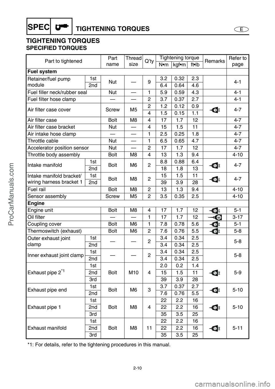
ESPECTIGHTENING TORQUES
TIGHTENING TORQUES
SPECIFIED TORQUES
Part to tightenedPart
nameThread
sizeQ’tyTightening torque
RemarksRefer to
page
Nmkgfmftlb
Fuel system
Retainer/fuel pump
module1st
Nut—93.20.322.3
4-1
2nd 6.4 0.64 4.6
Fuel filler neck/rubber seal Nut—1 5.9 0.59 4.3 4-1
Fuel filter hose clamp——2 3.7 0.37 2.7 4-1
Air filter case cover Screw M52 1.2 0.12 0.9
572LT4-7
4 1.5 0.15 1.1
Air filter case Bolt M8 4 17 1.7 12 4-7
Air filter case bracket Nut—4 15 1.5 11 4-7
Air intake hose clamp——1 2.5 0.25 1.8 4-7
Throttle cable Nut—1 6.5 0.65 4.7 4-7
Accelerator position sensor Nut—2 17 1.7 12 4-7
Throttle body assembly Bolt M8 4 13 1.3 9.4 4-10
Intake manifold1st
Bolt M6 28.80.886.4
242LT4-7
2nd 18 1.8 13
Intake manifold bracket/
wiring harness bracket 11st
Bolt M8 215 1.5 11
271LT4-7
2nd 39 3.9 28
Fuel rail Bolt M8 2 13 1.3 9.4 4-10
Sensor assembly Screw M5 2 3.5 0.35 2.5 4-10
Engine
Engine unit Bolt M8 4 17 1.7 12
271LT5-1
Oil filter——1171.712
E3-17
Coupling cover Bolt M6 1 7.8 0.78 5.6
572LT5-1
Thermoswitch (exhaust) Bolt M6 2 7.6 0.76 5.5
572LT5-8
Outer exhaust joint
clamp1st
——23.40.342.5
5-8
2nd 3.4 0.34 2.5
Inner exhaust joint clamp1st
——23.40.342.5
5-8
2nd 3.4 0.34 2.5
Exhaust pipe 2
*1 1st
Bolt M10 42.0 0.2 1.4242LT5-9 2nd 15 1.5 11
3rd 39 3.9 28
Exhaust pipe end1st
Bolt M6 33.70.372.7
572LT5-10
2nd 7.6 0.76 5.5
Exhaust pipe 11st
Bolt M8 422 2.2 16
242LT5-10 2nd 22 2.2 16
3rd 35 3.5 25
Exhaust manifold1st
Bolt M8 1122 2.2 16
242LT5-11 2nd 22 2.2 16
3rd 35 3.5 25
*1: For details, refer to the tightening procedures in this manual.
ProCarManuals.com
Page 33 of 347

2-12
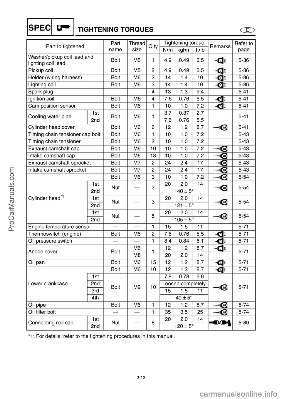
ESPECTIGHTENING TORQUES
Washer/pickup coil lead and
lighting coil leadBolt M5 1 4.9 0.49 3.5242LT5-36
Pickup coil Bolt M5 2 4.9 0.49 3.5
242LT5-36
Holder (wiring harness) Bolt M6 2 14 1.4 10
242LT5-36
Lighting coil Bolt M6 3 14 1.4 10
242LT5-36
Spark plug——4131.39.4 5-41
Ignition coil Bolt M6 4 7.6 0.76 5.5
572LT5-41
Cam position sensor Bolt M6 1 10 1.0 7.2
572LT5-41
Cooling water pipe1st
Bolt M6 13.70.372.7
5-41
2nd 7.6 0.76 5.5
Cylinder head cover Bolt M6 6 12 1.2 8.7
E5-41
Timing chain tensioner cap bolt Bolt M6 1 10 1.0 7.2 5-43
Timing chain tensioner Bolt M6 2 10 1.0 7.2 5-43
Exhaust camshaft cap Bolt M6 10 10 1.0 7.2
E5-43
Intake camshaft cap Bolt M6 18 10 1.0 7.2
E5-43
Exhaust camshaft sprocket Bolt M7 2 24 2.4 17
E5-43
Intake camshaft sprocket Bolt M7 2 24 2.4 17
E5-43
Cylinder head
*1 Bolt M6 3 10 1.0 7.2
E5-54
1st
Nut—220 2.0 14
E5-54
2nd 140 ±
5°
1st
Nut—320 2.0 14
E5-54
2nd 121 ±
5°
1st
Nut—520 2.0 14
E5-54
2nd 105 ±
5°
Engine temperature sensor——1 15 1.5 11 5-71
Thermoswitch (engine) Bolt M6 2 7.6 0.76 5.5
572LT5-71
Oil pressure switch——1 8.4 0.84 6.1
572LT5-71
Anode cover BoltM6
112 1.2 8.7
271LT5-71
M8 20 2.0 14
Oil pan Bolt M6 15 12 1.2 8.7
572LT5-71
Lower crankcaseBolt M6 10 12 1.2 8.7
572LT5-71
1st
Bolt M9 107.80.785.6
E5-71 2nd Loosen completely
3rd 15 1.5 11
4th 49 ±
5°
Oil pipe Bolt M6 1 12 1.2 8.7
E5-74
Oil filter bolt——1353.525
E5-74
Connecting rod cap1st
Nut—820 2.0 14
M5-80
2nd 120 ±
5°
*1: For details, refer to the tightening procedures in this manual.Part to tightenedPart
nameThread
sizeQ’tyTightening torque
RemarksRefer to
page
Nmkgfmftlb
ProCarManuals.com
Page 34 of 347

2-13
ESPECTIGHTENING TORQUES
Jet pump unit
Steering cable joint Nut — 1 6.8 0.68 4.9
242LT6-3
Ride plate Bolt M8 4 17 1.7 12
572LT6-1
Intake grate BoltM6
27.60.765.5
242LT6-1
M10 40 4.0 29
Speed sensor Screw M5 4 3.7 0.37 2.7
242LT6-1
Jet pump unit assembly BoltM6 1 7.8 0.78 5.6
572LT6-3
M10 4 40 4.0 29
Rubber plateBolt M6 4
6.80.684.9 6-3
Nut — 2
Bracket Bolt M8 217 1.7 12
6-3
14 1.4 10
271LT
Reverse gate Bolt M8 2 15 1.5 11271LT6-5
Reverse gate ball joint Nut — 1 7.8 0.78 5.6
242LT6-5
Reverse gate spring Nut — 1 7.8 0.78 5.6
242LT6-5
Spout hose clamp — —1 1.2 0.12 0.9 6-5
1 2.2 0.22 1.6 6-3
Jet thrust nozzle Bolt M8 2 15 1.5 11
271LT6-6
Nozzle/bracket Bolt M10 4 40 4.0 29
572LT6-6
Water inlet cover/water inlet
strainerBolt M6 4 6.6 0.66 4.8
572LT6-6
Cap Bolt M6 3 7.8 0.78 5.6
572LT6-8
Impeller Impeller M22 1 75 7.5 54
572LT6-8
Transom plate Nut — 4 26 2.6 19 6-15
Intermediate housing cover Bolt M8 4 17 1.7 12
271LT6-18
Driven couplingDriven
couplingM24 1 36 3.6 26
572LT6-19
Clamp — — 2 4.2 0.42 3.0 6-18
Hull and hood
Handlebar holder Bolt M8 4 20 2.0 14
572LT8-1
Upper handlebar cover ScrewM4 2 1.1 0.11 0.8
8-1
M5 4 1.1 0.11 0.8
Lower handlebar cover Screw M6 4 3.7 0.37 2.7
271LT8-1
Throttle lever assembly Screw M5 2 3.4 0.34 2.5 8-4
Handlebar switch assembly Screw M5 2 3.4 0.34 2.5 8-4
Grip end Bolt M5 2 1.2 0.12 0.9
242LT8-4
Steering column Bolt M8 4 17 1.7 12
572LT8-20
Steering cable ball joint Ball joint — 1 6.9 0.69 5.0 8-20
Steering arm Bolt M8 1 20 2.0 14
242LT8-20
Steering sensor Bolt M8 4 16 1.6 12
572LT8-21
Spacer Bolt M8 3 16 1.6 12
572LT8-21
Shift cable holder
(Deluxe model only)Bolt M6 2 6.9 0.69 5.0
242LT8-23
Shift cable seal
(Deluxe model only)Nut — 1 5.9 0.59 4.3 8-23 Part to tightenedPart
nameThread
sizeQ’tyTightening torque
RemarksRefer to
page
Nm kgfm ftlb
ProCarManuals.com
Page 35 of 347

2-14
ESPECTIGHTENING TORQUES
Shift cable locknut
(Deluxe model only)Nut—1 3.8 0.38 2.7572LT8-23
Steering cable locknut
(steering column side)Nut—1 6.5 0.65 4.7 8-23
Steering cable locknut
(jet pump side)Nut—1 6.8 0.68 4.9
572LT8-23
Steering cable seal Nut—1 5.9 0.59 4.3 8-23
Steering cable bracket Bolt M6 1 6.9 0.69 5.0
572LT8-23
Speed sensor lead grommet Nut—1 5.9 0.59 4.3 8-23
Hinge assembly Bolt M6 2 6.9 0.69 5.0 8-8
Hood lock assembly Bolt M5 2 1.9 0.19 1.4
572LT8-8
Hinge assembly Bolt M6 4 6.9 0.69 5.0
242LT8-8
Lid lock hook Bolt M6 2 6.9 0.69 5.0
242LT8-8
Mirror (Deluxe model only) Nut—4 15 1.5 11 8-8
Shift handle lever
(Deluxe model only)Screw M5 2 3.70.372.7
572LT8-11
Multifunction meter Bolt M5 4 3.9 0.39 2.8
572LT8-11
Engine hatch cover
(Deluxe model only)Bolt M6 1 6.9 0.69 5.0
572LT8-11
Engine hatch cover Bolt M6 8 6.9 0.69 5.0
572LT8-11
Detent plate Bolt M6 2 8.0 0.8 5.8
572LT8-16
Shift lever bracket
(Deluxe model only)Nut—2 15 1.5 11 8-16
Pilot water outlet Nut—1 4.2 0.42 3.0 8-17
Hand grip Nut—4 6.9 0.69 5.0 8-28
Seat bracket Nut—2 15 1.5 11 8-28
Seat lock projection Bolt—1 26 2.6 19 8-28
Seat lock assembly Bolt M6 2 6.4 0.64 4.6
271LT8-28
Plate/rubber hose/exhaust
valveNut—6 5.4 0.54 3.9 8-31
Hose clamp 1——2 3.7 0.37 2.7 8-31
Hose clamp 2——1 3.7 0.37 2.7 8-31
Joint clamp 1 and 4——2 3.7 0.37 2.7 8-31
Joint clamp 2 and 31st
——22.40.241.7
8-31
2nd 2.4 0.24 1.7
Sponson Bolt M810161.612
572LT8-36
Cleat Nut—2
15 1.5 11 8-36
4
Spout Nut—1 5.4 0.54 3.9 8-36
Protector (bow) Nut—5 6.9 0.69 5.0 8-36
Bow eye Bolt M6 2 13 1.3 9.4 8-36
Drain plug/packing Screw M5 4 2.0 0.2 1.4 8-36
Engine mount Bolt M8 8 17 1.7 12
572LT8-38
Engine damper Bolt M6 2 6.6 0.66 4.8
271LT8-38 Part to tightenedPart
nameThread
sizeQ’tyTightening torque
RemarksRefer to
page
Nmkgfmftlb
ProCarManuals.com
Page 37 of 347

2-16
ESPECCABLE AND HOSE ROUTING
CABLE AND HOSE ROUTING
K
E2
1
3
4
5
6
7
8
90
D
C
A
B
Ê
ÈÉ
1
2
5
6
7
6
J
A
A
H
I
G
F
0
62 7
K-K
J-J
I-I
H-H
G-G
A-A
B-B
C-C
D-D
E-E
F-F
BB
CC
EE
FF
DD
II
II
GG
H
H
K
KJ
J
A
A
BB
1Fuel tank breather hose
2Steering cable
3Throttle cable
4Fuse box
5Starter motor lead
6Positive battery lead
7Negative battery lead
8Battery
9Cooling water outlet hose
0Shift cable (Deluxe model only)
ASpeed sensor leadBCooling water inlet hose
CFuel hose
DElectric fuel pump
EAccelerator position sensor
FAntenna lead (Deluxe model only)
GRemote control unit lead (Deluxe model only)
HBilge hose joint
ICooling water hose joint
JCooling water pilot outlet hose
KAccelerator position sensor lead
ProCarManuals.com
Page 38 of 347

2-17
ESPECCABLE AND HOSE ROUTING
K
E2
1
3
4
5
6
7
8
90
D
C
A
B
Ê
ÈÉ
1
2
5
6
7
6
J
A
A
H
I
G
F
0
62 7
K-K
J-J
I-I
H-H
G-G
A-A
B-B
C-C
D-D
E-E
F-F
BB
CC
EE
FF
DD
II
II
GG
H
H
K
KJ
J
A
A
BB
ÈFasten the speed sensor lead, fuel sender lead,
wiring harness, and antenna lead (Deluxe
model only) with plastic tie 1 at the white tape on
the wiring harness.
ÉFasten the steering sensor lead, handlebar
switch lead, multifunction meter lead, and
buzzer lead with plastic tie 2.
ÊTo install the cooling water inlet hose, align the
white paint mark on the hose with the parting
line on the hose joint.
ProCarManuals.com
Page 39 of 347

2-18
ESPECCABLE AND HOSE ROUTING
12
Ð
Ò
Ó
Õ
Î
ÍÌ
È
É
È
É
Ñ
Ô
3
4
5678
4
B
O
P
5
N
C
D
A09H-H
EFGH
I
P
G
G-G
A
BD
F C
E
JJ
M
C
F
I
I
E
DB
A
A
ÏÐ
H
H
G
G
JK
0
Q
L
Ê
Ë
1Multifunction meter
2Handlebar switch lead
3Buzzer
4Shift cable (Deluxe model only)
5Fuel hose
6Relay assembly
7Fuse box
8ECM
9Positive battery lead
0Flushing hose
ACooling water outlet hoseBBilge hose
CBattery breather hose
DBattery
ENegative battery lead
FStarter motor lead
GSpeed sensor lead
HSteering cable
IRemote control unit lead (Deluxe model only)
JFuel tank breather hose
KAntenna lead (Deluxe model only)
LVentilation hose
ProCarManuals.com
Page 40 of 347

2-19
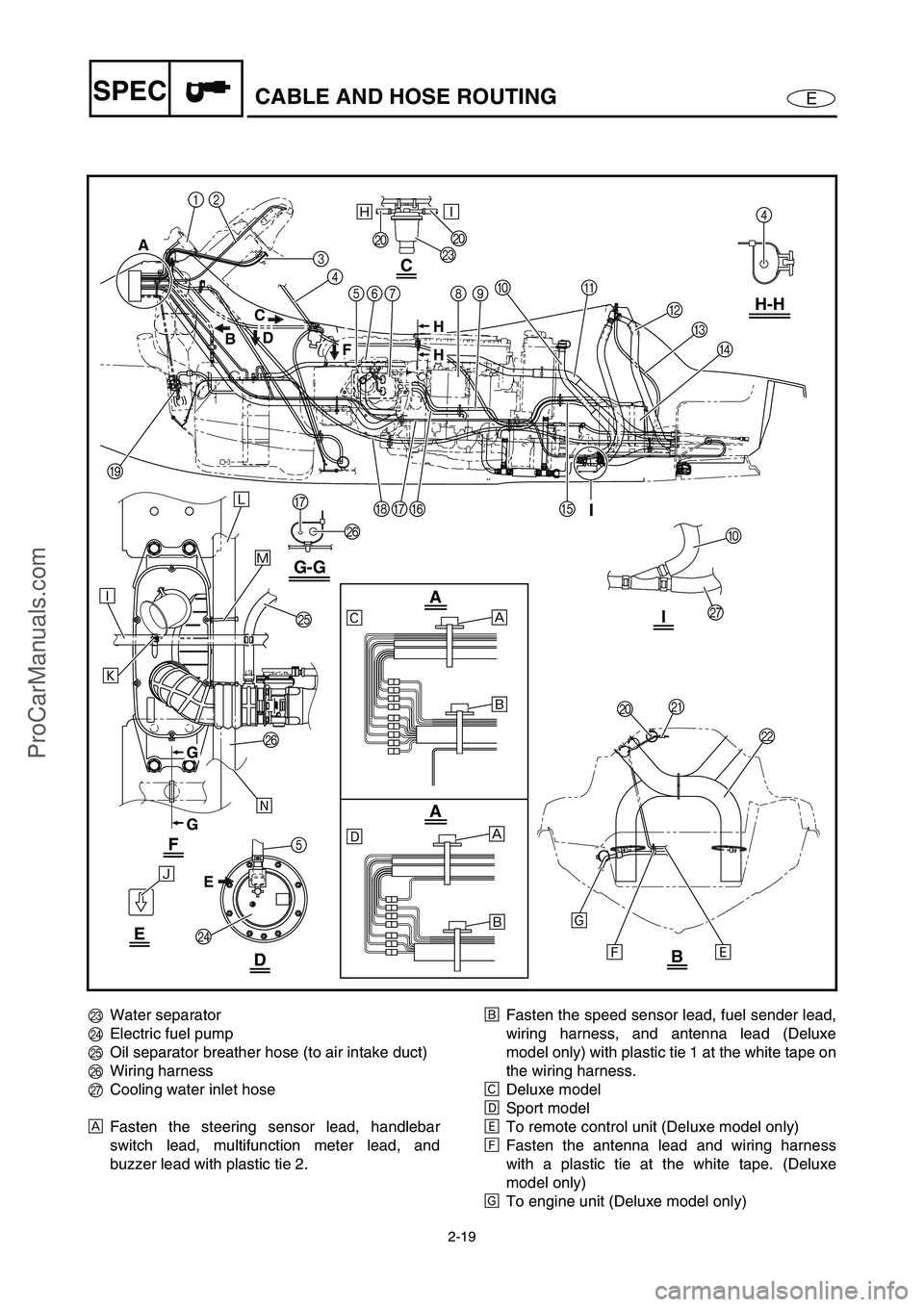
ESPECCABLE AND HOSE ROUTING
12
Ð
Ò
Ó
Õ
Î
ÍÌ
È
É
È
É
Ñ
Ô
3
4
5678
4
B
O
P
5
N
C
D
A09H-H
EFGH
I
P
G
G-G
A
BD
F C
E
JJ
M
C
F
I
I
E
DB
A
A
ÏÐ
H
H
G
G
JK
0
Q
L
Ê
Ë
MWater separator
NElectric fuel pump
OOil separator breather hose (to air intake duct)
PWiring harness
QCooling water inlet hose
ÈFasten the steering sensor lead, handlebar
switch lead, multifunction meter lead, and
buzzer lead with plastic tie 2.ÉFasten the speed sensor lead, fuel sender lead,
wiring harness, and antenna lead (Deluxe
model only) with plastic tie 1 at the white tape on
the wiring harness.
ÊDeluxe model
ËSport model
ÌTo remote control unit (Deluxe model only)
ÍFasten the antenna lead and wiring harness
with a plastic tie at the white tape. (Deluxe
model only)
ÎTo engine unit (Deluxe model only)
ProCarManuals.com