fuse YAMAHA WOLVERINE 2016 Owners Manual
[x] Cancel search | Manufacturer: YAMAHA, Model Year: 2016, Model line: WOLVERINE, Model: YAMAHA WOLVERINE 2016Pages: 192, PDF Size: 4.38 MB
Page 8 of 192

Valve clearance .................................. 8-41
Brakes ................................................ 8-41
Checking the front and rear brake pads.................................................. 8-41
Checking the brake fluid level ............ 8-42
Brake fluid replacement ..................... 8-43
Checking the brake pedal .................. 8-43
Parking brake ..................................... 8-44
Brake light switch adjustment ............ 8-44
Cable inspection and lubrication........ 8-45
Brake pedal and accelerator pedal
lubrication ......................................... 8-45
Checking the stabilizer bushes .......... 8-46
Rear knuckle upper and lower pivot
lubrication (left and right) .................. 8-46
Steering shaft lubrication ................... 8-47
Wheel removal.................................... 8-47
Checking and tightening the bead lock .................................................. 8-48
Tire replacement ................................ 8-48
Wheel installation ............................... 8-49
Battery ................................................ 8-50
Jump-starting ..................................... 8-53 Fuse replacement ...............................8-54
Replacing a headlight bulb .................8-57
Headlight beam adjustment ...............8-59
Tail/brake light bulb replacement .......8-60
Troubleshooting ..................................8-60
Troubleshooting charts .......................8-62
CLEANING AND STORAGE ....................9-1 Cleaning................................................9-1
Storage .................................................9-2
SPECIFICATIONS..................................10-1
CONSUMER INFORMATION ................11-1 Identification number records.............11-1
INDEX ....................................................12-1
UBN57AE0.book Page 3 Tuesday, November 24, 2015 1:42 PM
Page 38 of 192
3-2
3
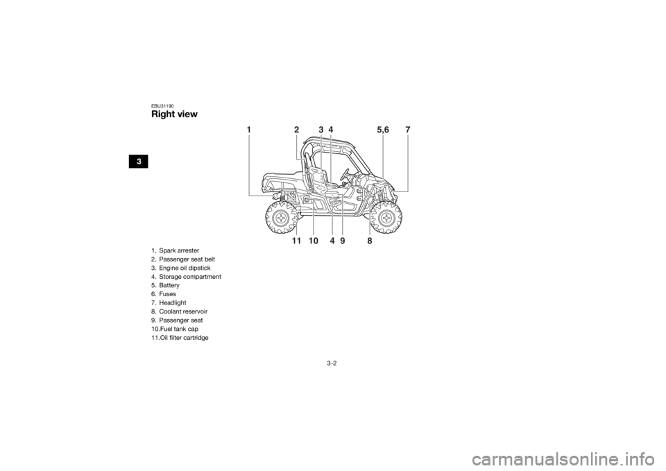
EBU31190Right view
10
9
4
118
3
4
5,6
1
7
2
1. Spark arrester
2. Passenger seat belt
3. Engine oil dipstick
4. Storage compartment
5. Battery
6. Fuses
7. Headlight
8. Coolant reservoir
9. Passenger seat
10.Fuel tank cap
11.Oil filter cartridgeUBN57AE0.book Page 2 Tuesday, November 24, 2015 1:42 PM
Page 73 of 192
4-34
4
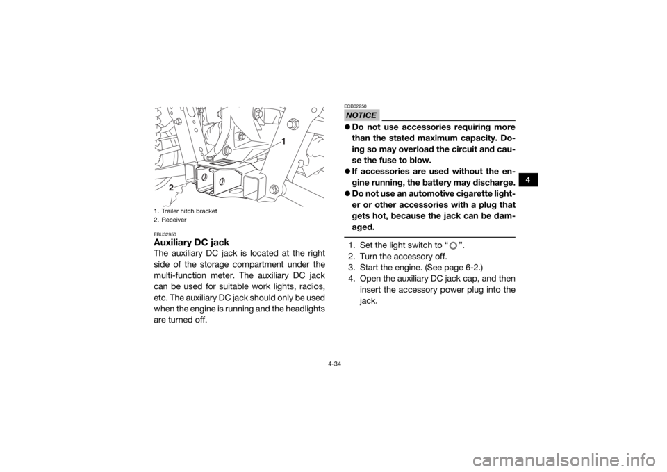
EBU32950Auxiliary DC jackThe auxiliary DC jack is located at the right
side of the storage compartment under the
multi-function meter. The auxiliary DC jack
can be used for suitable work lights, radios,
etc. The auxiliary DC jac k s h o u l d o n l y b e u s e d
when the engine is running and the headlights
are turned off.
NOTICEECB02250 Do not use accessories requiring more
than the stated maximum capacity. Do-
ing so may overload the circuit and cau-
se the fuse to blow.
If accessories are used without the en-
gine running, the ba ttery may discharge.
Do not use an automotive cigarette light-
er or other accessories with a plug that
gets hot, because the jack can be dam-
aged. 1. Set the light switch to “ ”.
2. Turn the accessory off.
3. Start the engine. (See page 6-2.)
4. Open the auxiliary DC jack cap, and then
insert the accessory power plug into the
jack.
1. Trailer hitch bracket
2. Receiver
1
2
UBN57AE0.book Page 34 Tuesday, November 24, 2015 1:42 PM
Page 169 of 192
8-54
8
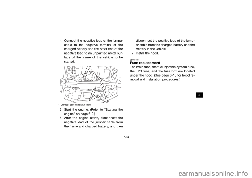
4. Connect the negative lead of the jumpercable to the negative terminal of the
charged battery and the other end of the
negative lead to an unpainted metal sur-
face of the frame of the vehicle to be
started.
5. Start the engine. (Refer to “Starting the engine” on page 6-2.)
6. After the engine starts, disconnect the
negative lead of the jumper cable from
the frame and charged battery, and then disconnect the positive lead of the jump-
er cable from the charged battery and the
battery in the vehicle.
7. Install the hood.
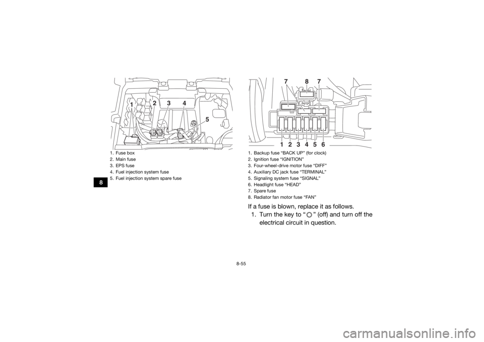
EBU33100Fuse replacementThe main fuse, the fuel injection system fuse,
the EPS fuse, and the fuse box are located
under the hood. (See page 8-10 for hood re-
moval and installation procedures.)
1. Jumper cable negative lead
1
UBN57AE0.book Page 54 Tuesday, November 24, 2015 1:42 PM
Page 170 of 192
8-55
8
If a fuse is blown, replace it as follows.1. Turn the key to “ ” (off) and turn off the
electrical circuit in question.
1. Fuse box
2. Main fuse
3. EPS fuse
4. Fuel injection system fuse
5. Fuel injection system spare fuse
1 3
2
4
5
1. Backup fuse “BACK UP” (for clock)
2. Ignition fuse “IGNITION”
3. Four-wheel-drive motor fuse “DIFF”
4. Auxiliary DC jack fuse “TERMINAL”
5. Signaling system fuse “SIGNAL”
6. Headlight fuse “HEAD”
7. Spare fuse
8. Radiator fan motor fuse “FAN”
1
2
3
4
5
6
8
7
7
UBN57AE0.book Page 55 Tuesday, November 24, 2015 1:42 PM
Page 171 of 192
8-56
8
NOTICEECB00641To prevent accidental short-circuiting,
turn off the main switch when checking or
replacing a fuse. 2. Remove the hood. (See page 8-10 forhood removal and installation proce-
dures.)
3. Remove the blown fuse, and then install a new fuse of the specified amperage.
WARNING! Always use a fuse of the specified amperage. Never use any
material in place of the proper fuse.
Using an improper fuse can cause
damage to the electrical system and
may lead to a fire.
[EWB03440]
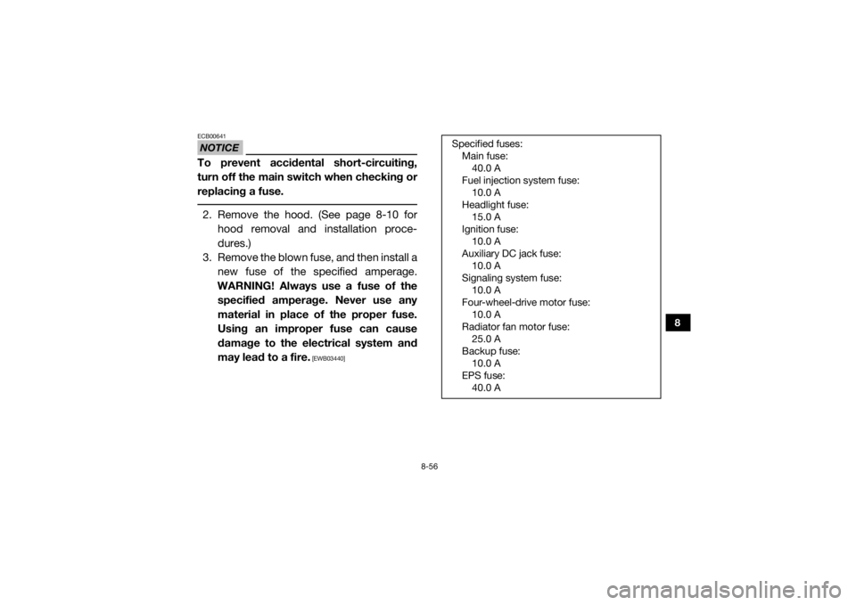
Specified fuses: Main fuse:40.0 A
Fuel injection system fuse: 10.0 A
Headlight fuse: 15.0 A
Ignition fuse: 10.0 A
Auxiliary DC jack fuse: 10.0 A
Signaling system fuse: 10.0 A
Four-wheel-drive motor fuse: 10.0 A
Radiator fan motor fuse: 25.0 A
Backup fuse: 10.0 A
EPS fuse: 40.0 A
UBN57AE0.book Page 56 Tuesday, November 24, 2015 1:42 PM
Page 172 of 192
8-57
8
4. Turn the key to “ ” (on) and turn on theelectrical circuit in question to check if
the device operates. If the fuse blows
again immediately, have a Yamaha dealer
check the electrical system.
5. Install the hood.EBU32670Replacing a headlight bulbIf a headlight bulb burns out, replace it as fol-
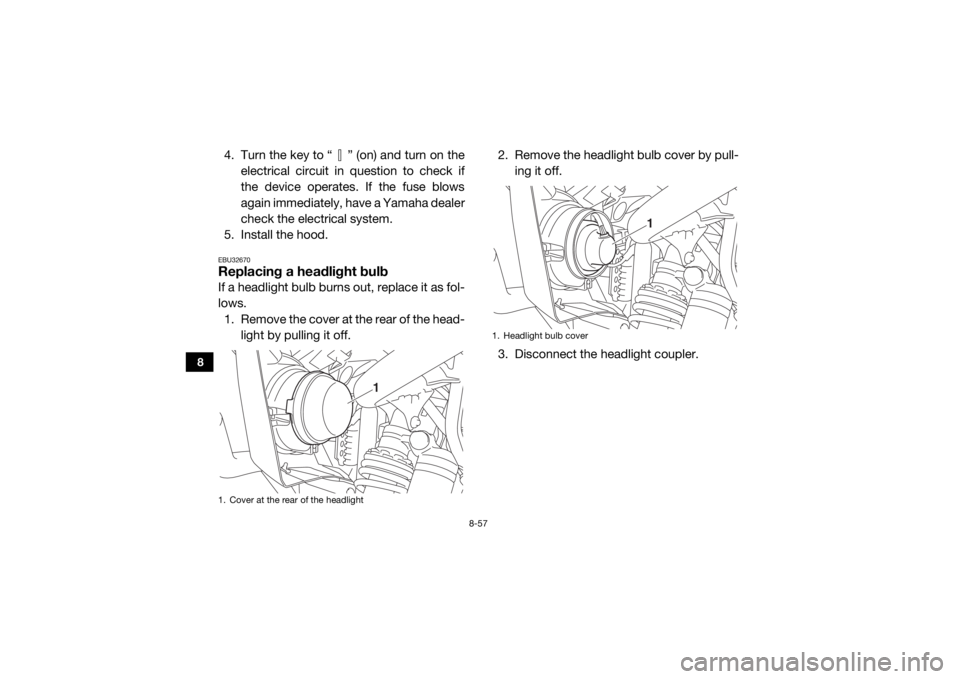
lows. 1. Remove the cover at the rear of the head- light by pulling it off. 2. Remove the headlight bulb cover by pull-
ing it off.
3. Disconnect the headlight coupler.1. Cover at the rear of the headlight
1
1. Headlight bulb cover
1
UBN57AE0.book Page 57 Tuesday, November 24, 2015 1:42 PM
Page 186 of 192

10-5
10
EPS warning light:LED
Helmet/Seat belt indicator light: 14 V, 0.85 W × 2Fuses:Main fuse:
40.0 A
Fuel injection system fuse: 10.0 A
EPS fuse:
40.0 A
Headlight fuse: 15.0 A
Signaling system fuse: 10.0 A
Ignition fuse:
10.0 A
Auxiliary DC jack fuse: 10.0 A
Backup fuse: 10.0 A
Four-wheel-drive motor fuse:
10.0 A
Radiator fan motor fuse: 25.0 A
EBU33220For Europe only
The figures quoted are emission levels and
are not necessarily safe working levels. Whilst
there is a correlation between the emission
and exposure levels, this cannot be used reli-
ably to determine whether or not further pre-
cautions are required. Factors that influence
the actual level of exposure of work-force in-
clude the characteristics of the work room,
the other sources of noise, etc. i.e. the num-
ber of machines and other adjacent process-
es, and the length of time for which an
operator is exposed to the noise. Also the
permissible exposure level can vary from
country. This information, however, will en-
able the user of the machine to make a better
evaluation of the hazard and risk.
UBN57AE0.book Page 5 Tuesday, November 24, 2015 1:42 PM
Page 189 of 192

12-1
12
INDEX
AAccelerator pedal ......................................................... 4-12
Accelerator pedal, Pre-operation check ........................ 5-7
Air filter case/air duct check hose, cleaning ................ 8-38
Air filter element, cleaning ........................................... 8-34
Auxiliary DC jack .......................................................... 4-34
Axle boots .................................................................... 8-31BBasic guide for safe use ................................................ 7-1
Battery, Periodic maintenance .................................... 8-50
Bead lock, checking and tightening ............................ 8-48
Brake fluid level, checking ........................................... 8-42
Brake fluid, replacing ................................................... 8-43
Brake light switch, adjusting ........................................ 8-44
Brake pedal .................................................................. 4-12
Brake pedal and accelerator pedal, lubrication ........... 8-45
Brake pedal, checking ................................................. 8-43
Brakes, Periodic maintenance ..................................... 8-41
Brakes, Pre-operation check ......................................... 5-3CCable, inspecting and lubrication ................................ 8-45
Cargo bed .................................................................... 4-22
Cleaning ......................................................................... 9-1
Control cables, Pre-operation check ............................. 5-8
Coolant, Periodic maintenance ................................... 8-25
Coolant, Pre-operation check ........................................ 5-6
Coolant temperature warning light ................................ 4-4
Cup holders ................................................................. 4-21
DDifferential gear oil, Periodic maintenance .................. 8-22
Differential gear oil, Pre-operation check ...................... 5-6
Doors ........................................................................... 4-15
Driver seat position ...................................................... 4-16
Drive select lever ......................................................... 4-14
Drive select lever operation and reverse driving ............ 6-3EEngine break-in .............................................................. 6-1
Engine oil and oil filter cartridge, Periodic maintenance .............................................................. 8-14
Engine oil, Pre-operation check .................................... 5-5
Engine trouble warning light .......................................... 4-4
EPS warning light .......................................................... 4-5FFinal gear oil, Periodic maintenance ............................ 8-20
Final gear oil, Pre-operation check ................................ 5-6
Fittings and fasteners, Pre-operation check ................. 5-8
Front and rear brake pads, checking .......................... 8-41
Fuel, Pre-operation check ............................................. 5-3
Fuel tank cap ............................................................... 4-14
Fuse, replacing ............................................................ 8-54GGlove compartment ..................................................... 4-17HHeadlight beam, adjusting ........................................... 8-59
Headlight bulb, replacing ............................................. 8-57
Helmet indicator light ..................................................... 4-5
High-range indicator light .............................................. 4-2
Hood ............................................................................ 8-10
Horn switch .................................................................. 4-12
UBN57AE0.book Page 1 Tuesday, November 24, 2015 1:42 PM