engine YAMAHA WR 250F 2004 User Guide
[x] Cancel search | Manufacturer: YAMAHA, Model Year: 2004, Model line: WR 250F, Model: YAMAHA WR 250F 2004Pages: 864, PDF Size: 22.07 MB
Page 32 of 864
1 - 7
GEN
INFOIMPORTANT INFORMATION
EC133000GASKETS, OIL SEALS AND O-
RINGS
1. All gaskets, oil seals, and O-
rings should be replaced when
an engine is overhauled. All gas-
ket surfaces, oil seal lips, and O-
rings must be cleaned.
2. Properly oil all mating parts and
bearings during reassembly.
Apply grease to the oil seal lips.
EC134000LOCK WASHERS/PLATES AND
COTTER PINS
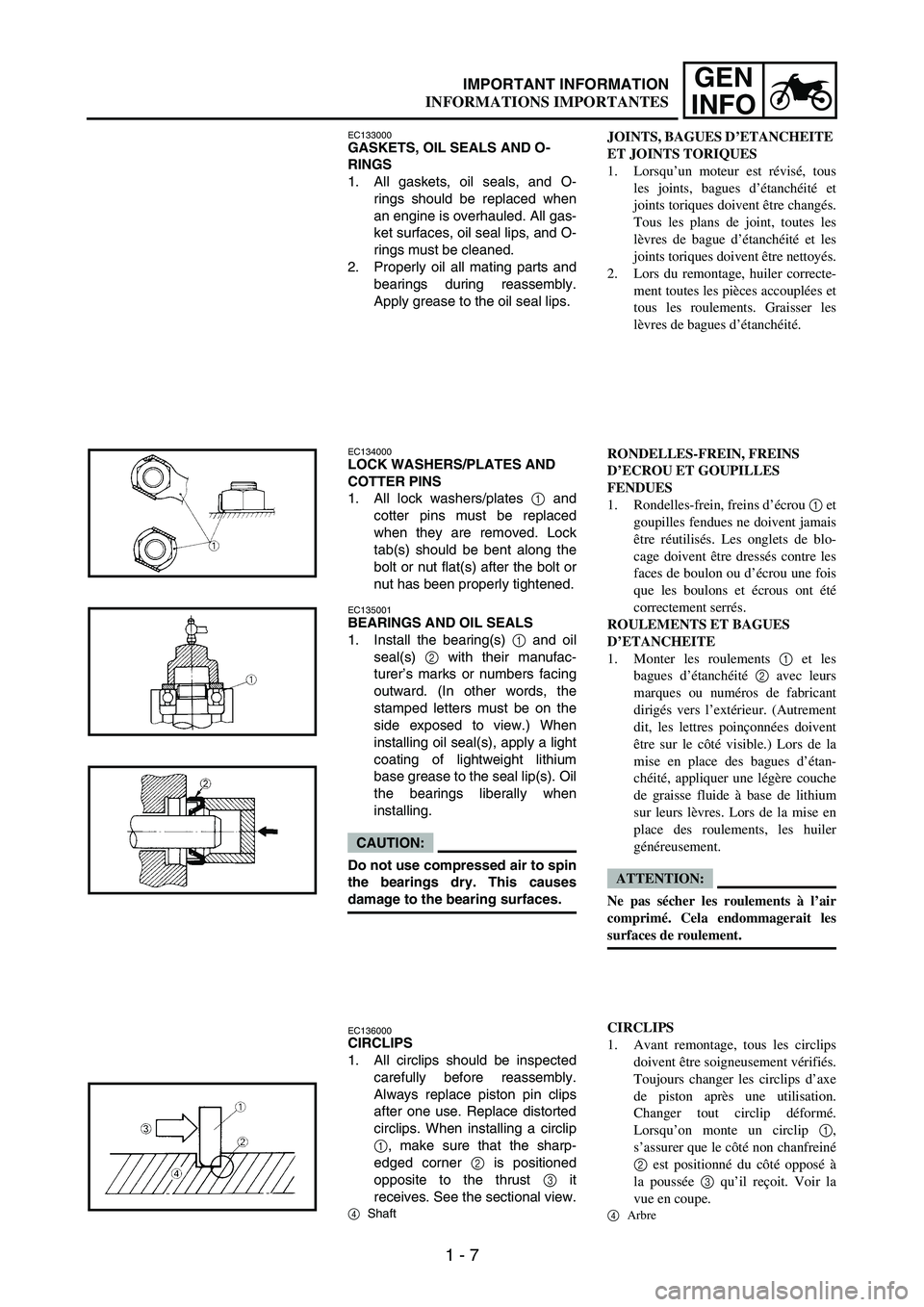
1. All lock washers/plates
1 and
cotter pins must be replaced
when they are removed. Lock
tab(s) should be bent along the
bolt or nut flat(s) after the bolt or
nut has been properly tightened.
EC135001BEARINGS AND OIL SEALS
1. Install the bearing(s)
1 and oil
seal(s)
2 with their manufac-
turer’s marks or numbers facing
outward. (In other words, the
stamped letters must be on the
side exposed to view.) When
installing oil seal(s), apply a light
coating of lightweight lithium
base grease to the seal lip(s). Oil
the bearings liberally when
installing.
CAUTION:
Do not use compressed air to spin
the bearings dry. This causes
damage to the bearing surfaces.
EC136000CIRCLIPS
1. All circlips should be inspected
carefully before reassembly.
Always replace piston pin clips
after one use. Replace distorted
circlips. When installing a circlip
1, make sure that the sharp-
edged corner
2 is positioned
opposite to the thrust
3 it
receives. See the sectional view.
4Shaft
JOINTS, BAGUES D’ETANCHEITE
ET JOINTS TORIQUES
1. Lorsqu’un moteur est révisé, tous
les joints, bagues d’étanchéité et
joints toriques doivent être changés.
Tous les plans de joint, toutes les
lèvres de bague d’étanchéité et les
joints toriques doivent être nettoyés.
2. Lors du remontage, huiler correcte-
ment toutes les pièces accouplées et
tous les roulements. Graisser les
lèvres de bagues d’étanchéité.
RONDELLES-FREIN, FREINS
D’ECROU ET GOUPILLES
FENDUES
1. Rondelles-frein, freins d’écrou 1 et
goupilles fendues ne doivent jamais
être réutilisés. Les onglets de blo-
cage doivent être dressés contre les
faces de boulon ou d’écrou une fois
que les boulons et écrous ont été
correctement serrés.
ROULEMENTS ET BAGUES
D’ETANCHEITE
1. Monter les roulements 1 et les
bagues d’étanchéité 2 avec leurs
marques ou numéros de fabricant
dirigés vers l’extérieur. (Autrement
dit, les lettres poinçonnées doivent
être sur le côté visible.) Lors de la
mise en place des bagues d’étan-
chéité, appliquer une légère couche
de graisse fluide à base de lithium
sur leurs lèvres. Lors de la mise en
place des roulements, les huiler
généreusement.
ATTENTION:
Ne pas sécher les roulements à l’air
comprimé. Cela endommagerait les
surfaces de roulement.
CIRCLIPS
1. Avant remontage, tous les circlips
doivent être soigneusement vérifiés.
Toujours changer les circlips d’axe
de piston après une utilisation.
Changer tout circlip déformé.
Lorsqu’on monte un circlip 1,
s’assurer que le côté non chanfreiné
2 est positionné du côté opposé à
la poussée 3 qu’il reçoit. Voir la
vue en coupe.
4
Arbre
INFORMATIONS IMPORTANTES
Page 52 of 864
1 - 27
GEN
INFO
EC150000
CONTROL FUNCTIONS
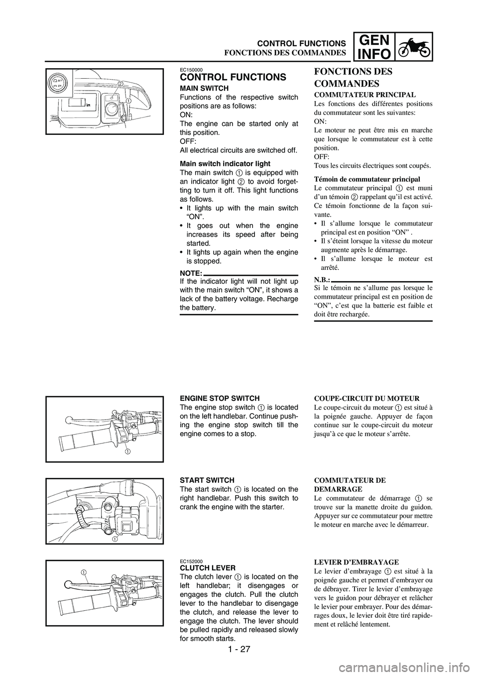
MAIN SWITCH
Functions of the respective switch
positions are as follows:
ON:
The engine can be started only at
this position.
OFF:
All electrical circuits are switched off.
Main switch indicator light
The main switch
1 is equipped with
an indicator light
2 to avoid forget-
ting to turn it off. This light functions
as follows.
It lights up with the main switch
“ON”.
It goes out when the engine
increases its speed after being
started.
It lights up again when the engine
is stopped.
NOTE:If the indicator light will not light up
with the main switch “ON”, it shows a
lack of the battery voltage. Recharge
the battery.
ENGINE STOP SWITCH
The engine stop switch
1 is located
on the left handlebar. Continue push-
ing the engine stop switch till the
engine comes to a stop.
START SWITCH
The start switch
1 is located on the
right handlebar. Push this switch to
crank the engine with the starter.
EC152000CLUTCH LEVER
The clutch lever
1 is located on the
left handlebar; it disengages or
engages the clutch. Pull the clutch
lever to the handlebar to disengage
the clutch, and release the lever to
engage the clutch. The lever should
be pulled rapidly and released slowly
for smooth starts.
FONCTIONS DES
COMMANDES
COMMUTATEUR PRINCIPAL
Les fonctions des différentes positions
du commutateur sont les suivantes:
ON:
Le moteur ne peut être mis en marche
que lorsque le commutateur est à cette
position.
OFF:
Tous les circuits électriques sont coupés.
Témoin de commutateur principal
Le commutateur principal 1 est muni
d’un témoin 2 rappelant qu’il est activé.
Ce témoin fonctionne de la façon sui-
vante.
Il s’allume lorsque le commutateur
principal est en position “ON” .
Il s’éteint lorsque la vitesse du moteur
augmente après le démarrage.
Il s’allume lorsque le moteur est
arrêté.
N.B.:
Si le témoin ne s’allume pas lorsque le
commutateur principal est en position de
“ON”, c’est que la batterie est faible et
doit être rechargée.
COUPE-CIRCUIT DU MOTEUR
Le coupe-circuit du moteur 1 est situé à
la poignée gauche. Appuyer de façon
continue sur le coupe-circuit du moteur
jusqu’à ce que le moteur s’arrête.
COMMUTATEUR DE
DEMARRAGE
Le commutateur de démarrage 1 se
trouve sur la manette droite du guidon.
Appuyer sur ce commutateur pour mettre
le moteur en marche avec le démarreur.
LEVIER D’EMBRAYAGE
Le levier d’embrayage 1 est situé à la
poignée gauche et permet d’embrayer ou
de débrayer. Tirer le levier d’embrayage
vers le guidon pour débrayer et relâcher
le levier pour embrayer. Pour des démar-
rages doux, le levier doit être tiré rapide-
ment et relâché lentement.
CONTROL FUNCTIONS
FONCTIONS DES COMMANDES
Page 54 of 864
1 - 29
GEN
INFO
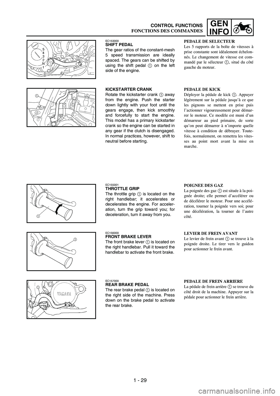
EC153000SHIFT PEDAL
The gear ratios of the constant-mesh
5 speed transmission are ideally
spaced. The gears can be shifted by
using the shift pedal
1 on the left
side of the engine.
KICKSTARTER CRANK
Rotate the kickstarter crank
1 away
from the engine. Push the starter
down lightly with your foot until the
gears engage, then kick smoothly
and forcefully to start the engine.
This model has a primary kickstarter
crank so the engine can be started in
any gear if the clutch is disengaged.
In normal practices, however, shift to
neutral before starting.
1
EC155001THROTTLE GRIP
The throttle grip
1 is located on the
right handlebar; it accelerates or
decelerates the engine. For acceler-
ation, turn the grip toward you; for
deceleration, turn it away from you.
EC156000FRONT BRAKE LEVER
The front brake lever
1 is located on
the right handlebar. Pull it toward the
handlebar to activate the front brake.
EC157000REAR BRAKE PEDAL
The rear brake pedal
1 is located on
the right side of the machine. Press
down on the brake pedal to activate
the rear brake.
PEDALE DE SELECTEUR
Les 5 rapports de la boîte de vitesses à
prise constante sont idéalement échelon-
nés. Le changement de vitesse est com-
mandé par le sélecteur 1, situé du côté
gauche du moteur.
PEDALE DE KICK
Déployer la pédale de kick 1. Appuyer
légèrement sur la pédale jusqu’à ce que
les pignons se mettent en prise puis
l’actionner vigoureusement pour démar-
rer le moteur. Ce modèle est muni d’un
démarreur au pied primaire, de sorte
qu’on peut démarrer à n’importe quelle
vitesse à condition de débrayer. Toute-
fois, normalement, on remettra les vites-
ses au point mort avant la mise en
marche.
POIGNEE DES GAZ
La poignée des gaz 1 est située à la poi-
gnée droite; elle permet d’accélérer ou
de décélérer le moteur. Pour une accélé-
ration, tourner la poignée vers soi; pour
une décélération, la tourner de l’autre
côté.
LEVIER DE FREIN AVANT
Le levier de frein avant 1 se trouve à la
poignée droite. Le tirer vers le guidon
pour actionner le frein avant.
PEDALE DE FREIN ARRIERE
La pédale de frein arrière 1 se trouve du
côté droit de la machine. Appuyer sur la
pédale pour actionner le frein arrière.
CONTROL FUNCTIONS
FONCTIONS DES COMMANDES
Page 56 of 864
1 - 31
GEN
INFO
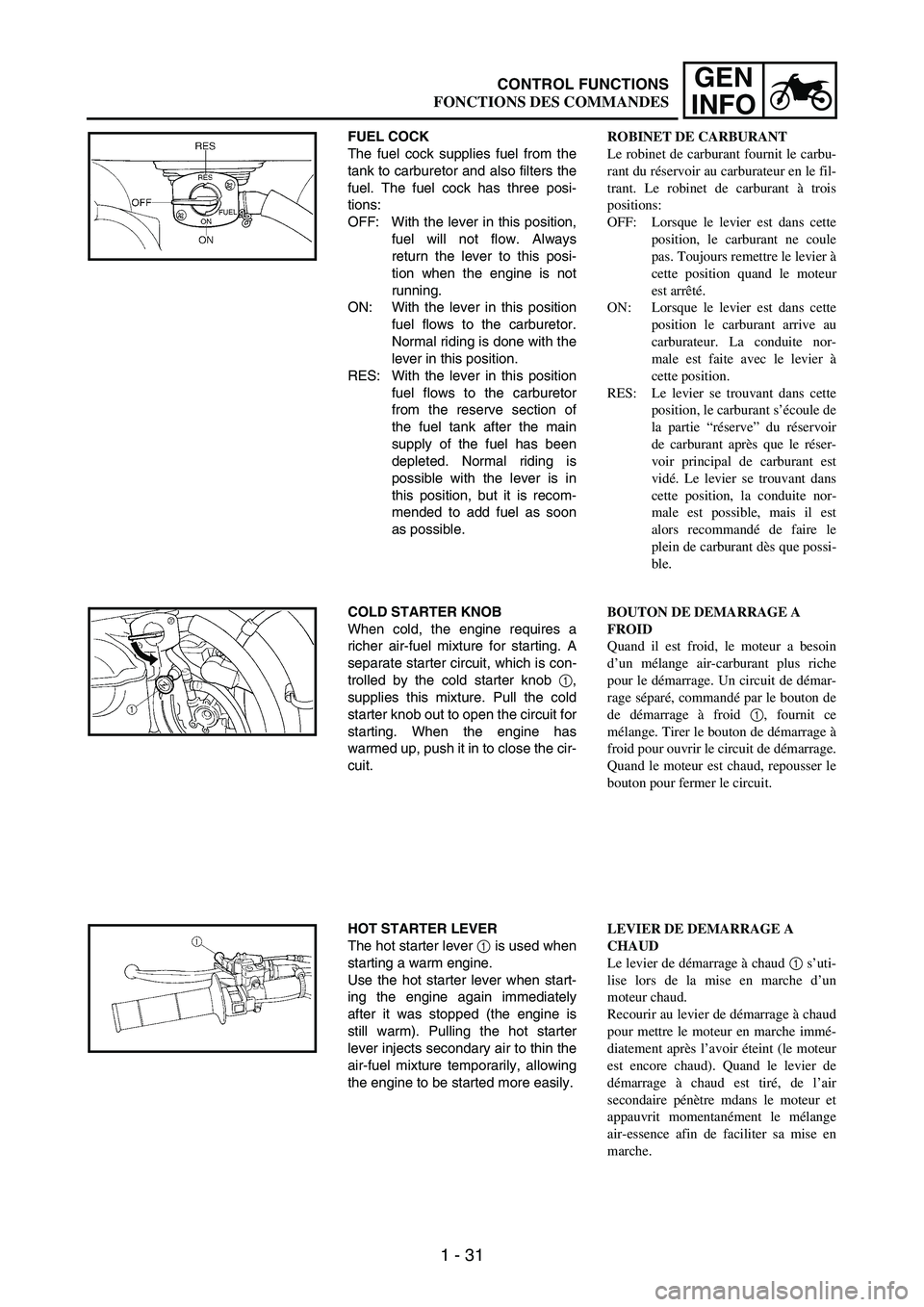
FUEL COCK
The fuel cock supplies fuel from the
tank to carburetor and also filters the
fuel. The fuel cock has three posi-
tions:
OFF: With the lever in this position,
fuel will not flow. Always
return the lever to this posi-
tion when the engine is not
running.
ON: With the lever in this position
fuel flows to the carburetor.
Normal riding is done with the
lever in this position.
RES: With the lever in this position
fuel flows to the carburetor
from the reserve section of
the fuel tank after the main
supply of the fuel has been
depleted. Normal riding is
possible with the lever is in
this position, but it is recom-
mended to add fuel as soon
as possible.
COLD STARTER KNOB
When cold, the engine requires a
richer air-fuel mixture for starting. A
separate starter circuit, which is con-
trolled by the cold starter knob
1,
supplies this mixture. Pull the cold
starter knob out to open the circuit for
starting. When the engine has
warmed up, push it in to close the cir-
cuit.
HOT STARTER LEVER
The hot starter lever
1 is used when
starting a warm engine.
Use the hot starter lever when start-
ing the engine again immediately
after it was stopped (the engine is
still warm). Pulling the hot starter
lever injects secondary air to thin the
air-fuel mixture temporarily, allowing
the engine to be started more easily.
ROBINET DE CARBURANT
Le robinet de carburant fournit le carbu-
rant du réservoir au carburateur en le fil-
trant. Le robinet de carburant à trois
positions:
OFF: Lorsque le levier est dans cette
position, le carburant ne coule
pas. Toujours remettre le levier à
cette position quand le moteur
est arrêté.
ON: Lorsque le levier est dans cette
position le carburant arrive au
carburateur. La conduite nor-
male est faite avec le levier à
cette position.
RES: Le levier se trouvant dans cette
position, le carburant s’écoule de
la partie “réserve” du réservoir
de carburant après que le réser-
voir principal de carburant est
vidé. Le levier se trouvant dans
cette position, la conduite nor-
male est possible, mais il est
alors recommandé de faire le
plein de carburant dès que possi-
ble.
BOUTON DE DEMARRAGE A
FROID
Quand il est froid, le moteur a besoin
d’un mélange air-carburant plus riche
pour le démarrage. Un circuit de démar-
rage séparé, commandé par le bouton de
de démarrage à froid 1, fournit ce
mélange. Tirer le bouton de démarrage à
froid pour ouvrir le circuit de démarrage.
Quand le moteur est chaud, repousser le
bouton pour fermer le circuit.
LEVIER DE DEMARRAGE A
CHAUD
Le levier de démarrage à chaud 1 s’uti-
lise lors de la mise en marche d’un
moteur chaud.
Recourir au levier de démarrage à chaud
pour mettre le moteur en marche immé-
diatement après l’avoir éteint (le moteur
est encore chaud). Quand le levier de
démarrage à chaud est tiré, de l’air
secondaire pénètre mdans le moteur et
appauvrit momentanément le mélange
air-essence afin de faciliter sa mise en
marche.
CONTROL FUNCTIONS
FONCTIONS DES COMMANDES
Page 60 of 864
1 - 35
GEN
INFO
FUEL
Always use the recommended fuel
as stated below. Also, be sure to use
new gasoline the day of a race.
CAUTION:
Use only unleaded gasoline. The
use of leaded gasoline will cause
severe damage to the engine inter-
nal parts such as valves, piston
rings, and exhaust system, etc.
NOTE:If knocking or pinging occurs, use a
different brand of gasoline or higher
octane grade.
WARNING
For refueling, be sure to stop the
engine and use enough care not
to spill any fuel. Also be sure to
avoid refueling close to a fire.
Refuel after the engine, exhaust
pipe, etc. have cooled off.
Recommended fuel:
Except for ZA:
Premium unleaded
gasoline only with a
research octane
number of 95 or
higher.
For ZA:
Premium gasoline
CARBURANT
Toujours utiliser le carburant recomman-
dée décrit ci-dessous. D’autre part,
s’assurer d’utiliser de l’essence fraîche le
jour de la course.
ATTENTION:
Utiliser uniquement de l’essence sans
plomb. L’utilisation d’essence au
plomb entraînerait de graves domma-
ges aux parties internes du moteur
(valves, segments de piston, système
d’échappement, etc).
N.B.:
Si un cognement ou un cliquetis sur-
vient, utiliser une marque d’essence dif-
férente ou une classe d’octane
supérieure.
AVERTISSEMENT
Avant de faire le plein, arrêter le
moteur. Faire attention de ne pas
répandre de carburant sur la
machine. Ne pas faire le plein près
d’une flamme.
Faire le plein après avoir laissé
refroidir le moteur, le tuyau
d’échappement, etc.
Carburant préconisé:
Excepté pour ZA:
Essence super sans
plomb d’un indice
d’octane de recherche
de 95 ou plus.
Pour ZA:
Essence super
FUEL
CARBURANT
Page 62 of 864
1 - 37
GEN
INFO
STARTING AND
BREAK-IN
WARNING
Never start or run the engine in a
closed area. The exhaust fumes
are poisonous; they can cause
loss of consciousness and death
in a very short time. Always oper-
ate the machine in a well-venti-
lated area.
CAUTION:
The carburetor on this machine
has a built-in accelerator pump.
Therefore, when starting the
engine, do not operate the throt-
tle or the spark plug will foul.
Unlike a two-stroke engine, this
engine cannot be kick started
when the throttle is open
because the kickstarter may
kick back. Also, if the throttle is
open the air/fuel mixture may be
too lean for the engine to start.
Before starting the machine,
perform the checks in the pre-
operation check list.
AIR FILTER MAINTENANCE
According to “AIR FILTER CLEAN-
ING” section in the CHAPTER 3,
apply the foam-air-filter oil or its
equivalent to the element. (Excess
oil in the element may adversely
affect engine starting.)
STARTING A COLD ENGINE
NOTE:This model is equipped with an igni-
tion circuit cut-off system. The
engine can be started under the fol-
lowing conditions.
When the transmission is in neu-
tral.
When the clutch is disengaged
with the transmission in any posi-
tion. However, it is recommended
to shift into neutral before starting
the engine.
MISE EN MARCHE ET
RODAGE
AVERTISSEMENT
Ne jamais mettre le moteur en marche
dans un endroit clos. Les gaz d’échap-
pement sont nocifs et peuvent causer
une perte de conscience et même la
mort en quelques minutes. Toujours
faire marcher le moteur dans un
endroit bien ventilé.
ATTENTION:
Le carburateur de cette machine est
équipé d’une pompe d’accélération.
Il faut donc éviter d’actionner
l’accélérateur au moment de la mise
en marche du moteur, sous peine
d’encrasser la bougie.
Comme pour tous les quatre temps,
il ne faut pas actionner l’accéléra-
teur au moment d’actionner le kick,
sinon celui-ci risque de se relever
brutalement. De plus, l’ouverture
des gaz risque d’appauvrir à l’excès
le mélange air/carburant, ce qui
rendrait la mise en marche difficile.
Avant la mise en marche, effectuer
les vérifications indiquées dans la
liste de contrôle avant utilisation.
ENTRETIEN DU FILTRE A AIR
Comme indiqué dans “NETTOYAGE
DU FILTRE A AIR” au CHAPITRE 3,
appliquer de l’huile de filtre à air en
mousse ou une huile équivalente sur
l’élément. (L’excès d’huile peut empê-
cher le moteur de démarrer correcte-
ment).
MISE EN MARCHE D’UN MOTEUR
FROID
N.B.:
Cette machine est équipée d’un système
de coupure du circuit d’allumage. Les
conditions suivantes doivent être rem-
plies pour que le moteur puisse être mis
en marche.
La machine doit être au point mort.
L’embrayage doit être désengagé et
une vitesse quelconque sélectionnée.
Il est toutefois recommandé de passer
au point mort avant de mettre la
machine en marche.
STARTING AND BREAK-IN
MISE EN MARCHE ET RODAGE
Page 64 of 864
1 - 39
GEN
INFO
1. Inspect the coolant level.
2. Turn the fuel cock to “ON”.
3. Push on the main switch to “ON”.
4. Shift the transmission into neu-
tral.
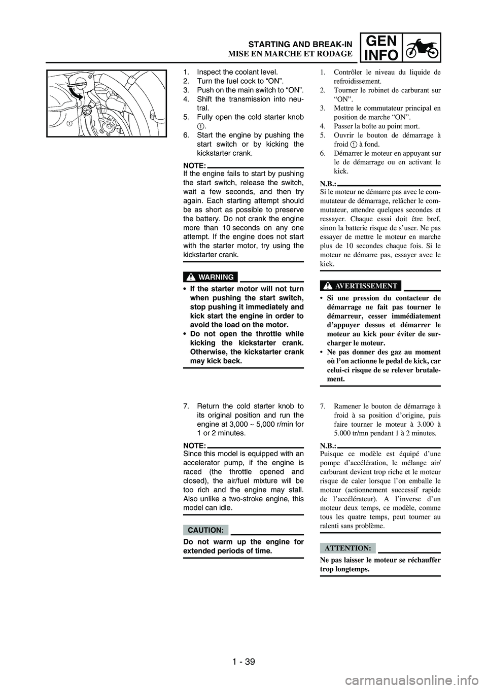
5. Fully open the cold starter knob
1.
6. Start the engine by pushing the
start switch or by kicking the
kickstarter crank.
NOTE:If the engine fails to start by pushing
the start switch, release the switch,
wait a few seconds, and then try
again. Each starting attempt should
be as short as possible to preserve
the battery. Do not crank the engine
more than 10 seconds on any one
attempt. If the engine does not start
with the starter motor, try using the
kickstarter crank.
WARNING
If the starter motor will not turn
when pushing the start switch,
stop pushing it immediately and
kick start the engine in order to
avoid the load on the motor.
Do not open the throttle while
kicking the kickstarter crank.
Otherwise, the kickstarter crank
may kick back.
7. Return the cold starter knob to
its original position and run the
engine at 3,000 ~ 5,000 r/min for
1 or 2 minutes.
NOTE:Since this model is equipped with an
accelerator pump, if the engine is
raced (the throttle opened and
closed), the air/fuel mixture will be
too rich and the engine may stall.
Also unlike a two-stroke engine, this
model can idle.
CAUTION:
Do not warm up the engine for
extended periods of time.1. Contrôler le niveau du liquide de
refroidissement.
2. Tourner le robinet de carburant sur
“ON”.
3. Mettre le commutateur principal en
position de marche “ON”.
4. Passer la boîte au point mort.
5. Ouvrir le bouton de démarrage à
froid 1 à fond.
6. Démarrer le moteur en appuyant sur
le de démarrage ou en activant le
kick.
N.B.:
Si le moteur ne démarre pas avec le com-
mutateur de démarrage, relâcher le com-
mutateur, attendre quelques secondes et
ressayer. Chaque essai doit être bref,
sinon la batterie risque de s’user. Ne pas
essayer de mettre le moteur en marche
plus de 10 secondes chaque fois. Si le
moteur ne démarre pas, essayer avec le
kick.
AVERTISSEMENT
Si une pression du contacteur de
démarrage ne fait pas tourner le
démarreur, cesser immédiatement
d’appuyer dessus et démarrer le
moteur au kick pour éviter de sur-
charger le moteur.
Ne pas donner des gaz au moment
où l’on actionne le pedal de kick, car
celui-ci risque de se relever brutale-
ment.
7. Ramener le bouton de démarrage à
froid à sa position d’origine, puis
faire tourner le moteur à 3.000 à
5.000 tr/mn pendant 1 à 2 minutes.
N.B.:
Puisque ce modèle est équipé d’une
pompe d’accélération, le mélange air/
carburant devient trop riche et le moteur
risque de caler lorsque l’on emballe le
moteur (actionnement successif rapide
de l’accélérateur). A l’inverse d’un
moteur deux temps, ce modèle, comme
tous les quatre temps, peut tourner au
ralenti sans problème.
ATTENTION:
Ne pas laisser le moteur se réchauffer
trop longtemps.
STARTING AND BREAK-IN
MISE EN MARCHE ET RODAGE
Page 66 of 864
1 - 41
GEN
INFO
STARTING A WARM ENGINE
Do not operate the cold starter knob
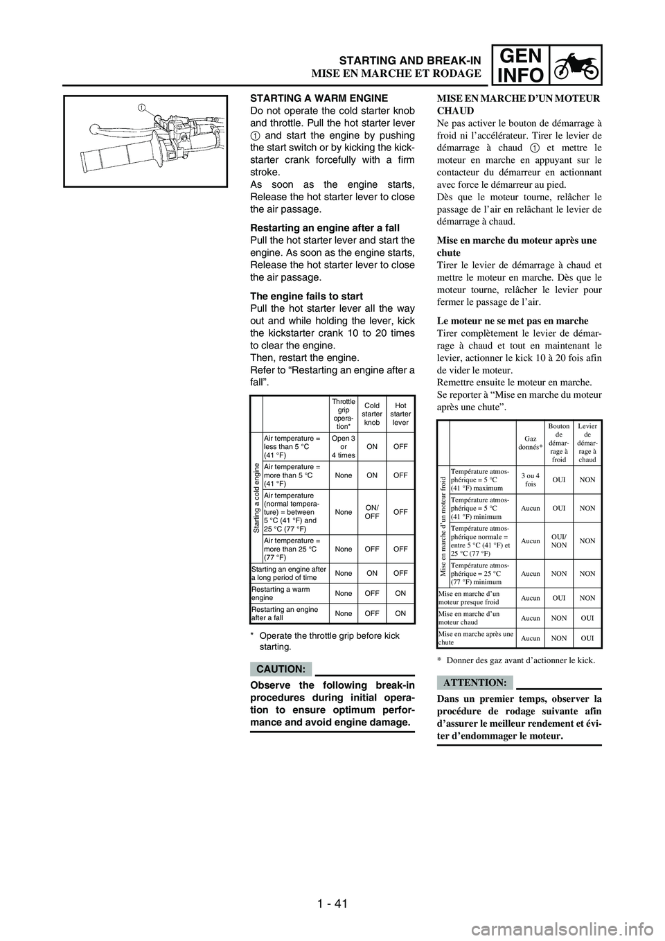
and throttle. Pull the hot starter lever
1 and start the engine by pushing
the start switch or by kicking the kick-
starter crank forcefully with a firm
stroke.
As soon as the engine starts,
Release the hot starter lever to close
the air passage.
Restarting an engine after a fall
Pull the hot starter lever and start the
engine. As soon as the engine starts,
Release the hot starter lever to close
the air passage.
The engine fails to start
Pull the hot starter lever all the way
out and while holding the lever, kick
the kickstarter crank 10 to 20 times
to clear the engine.
Then, restart the engine.
Refer to “Restarting an engine after a
fall”.
* Operate the throttle grip before kick
starting.
CAUTION:
Observe the following break-in
procedures during initial opera-
tion to ensure optimum perfor-
mance and avoid engine damage.
Throttle
grip
opera-
tion*Cold
starter
knobHot
starter
lever
Starting a cold engine
Air temperature =
less than 5 °C
(41°F)Open 3
or
4 timesON OFF
Air temperature =
more than 5 °C
(41°F)None ON OFF
Air temperature
(normal tempera-
ture) = between
5°C (41°F) and
25°C (77°F)NoneON/
OFFOFF
Air temperature =
more than 25 °C
(77 °F)None OFF OFF
Starting an engine after
a long period of timeNone ON OFF
Restarting a warm
engineNone OFF ON
Restarting an engine
after a fallNone OFF ON
MISE EN MARCHE D’UN MOTEUR
CHAUD
Ne pas activer le bouton de démarrage à
froid ni l’accélérateur. Tirer le levier de
démarrage à chaud 1 et mettre le
moteur en marche en appuyant sur le
contacteur du démarreur en actionnant
avec force le démarreur au pied.
Dès que le moteur tourne, relâcher le
passage de l’air en relâchant le levier de
démarrage à chaud.
Mise en marche du moteur après une
chute
Tirer le levier de démarrage à chaud et
mettre le moteur en marche. Dès que le
moteur tourne, relâcher le levier pour
fermer le passage de l’air.
Le moteur ne se met pas en marche
Tirer complètement le levier de démar-
rage à chaud et tout en maintenant le
levier, actionner le kick 10 à 20 fois afin
de vider le moteur.
Remettre ensuite le moteur en marche.
Se reporter à “Mise en marche du moteur
après une chute”.
* Donner des gaz avant d’actionner le kick.
ATTENTION:
Dans un premier temps, observer la
procédure de rodage suivante afin
d’assurer le meilleur rendement et évi-
ter d’endommager le moteur.
Gaz
donnés*Bouton
de
démar-
rage à
froid Levier
de
démar-
rage à
chaud
Mise en marche d’un moteur froid
Température atmos-
phérique = 5°C
(41°F) maximum3 ou 4
foisOUI NON
Température atmos-
phérique = 5°C
(41°F) minimumAucun OUI NON
Température atmos-
phérique normale =
entre 5 °C (41 °F) et
25 °C (77°F)AucunOUI/
NONNON
Température atmos-
phérique = 25°C
(77°F) minimumAucun NON NON
Mise en marche d’un
moteur presque froidAucun OUI NON
Mise en marche d’un
moteur chaudAucun NON OUI
Mise en marche après une
chuteAucun NON OUI
STARTING AND BREAK-IN
MISE EN MARCHE ET RODAGE
Page 68 of 864
1 - 43
GEN
INFO
BREAK-IN PROCEDURES
1. Before starting the engine, fill the
fuel tank with the fuel.
2. Perform the pre-operation
checks on the machine.
3. Start and warm up the engine.
Check the idle speed, and check
the operation of the controls and
the engine stop switch. Then,
restart the engine and check its
operation within no more than 5
minutes after it is restarted.
4. Operate the machine in the
lower gears at moderate throttle
openings for five to eight min-
utes.
5. Check how the engine runs
when the machine is ridden with
the throttle 1/4 to 1/2 open (low
to medium speed) for about one
hour.
6. Restart the engine and check
the operation of the machine
throughout its entire operating
range. Restart the machine and
operate it for about 10 to 15
more minutes. The machine will
now be ready to race.
CAUTION:
After the break-in or before each
race, you must check the entire
machine for loose fittings and
fasteners as per “TORQUE-
CHECK POINTS”.
Tighten all such fasteners as
required.
When any of the following parts
have been replaced, they must
be broken in.
CYLINDER AND CRANKSHAFT:
About one hour of break-in
operation is necessary.
PISTON, RING, VALVES, CAM-
SHAFTS AND GEARS:
These parts require about 30
minutes of break-in operation at
half-throttle or less. Observe the
condition of the engine carefully
during operation.PROCEDURE DE RODAGE
1. Avant de mettre le moteur en mar-
che, faire le plein d’essence.
2. Effectuer les contrôles avant utilisa-
tion de la machine.
3. Lancer le moteur et le laisser se
réchauffer. Vérifier le régime de
ralenti, le fonctionnement des com-
mandes et l’efficacité du coupe-cir-
cuit. Remettre ensuite le moteur en
marche et vérifier son fonctionne-
ment dans les 5 minutes maximum.
4. Piloter la machine sur les rapports
inférieurs et à régime modéré durant
les cinq à huit premières minutes.
5. Vérifier le fonctionnement du
moteur en roulant pendant environ 1
heure à une ouverture des gaz de 1/4
à 1/2 (petite à moyenne vitesse) .
6. Remettre le moteur en marche et
vérifier son fonctionnement à tous
les régimes. Relancer le moteur et
piloter la machine pendant 10 à 15
minutes supplémentaires. Elle sera
alors prête pour la course.
ATTENTION:
Après le rodage ou avant chaque
course, il faut vérifier toutes les fixa-
tions et serrages comme indiqué
dans “POINTS DE VERIFICA-
TION DE COUPLE DE SER-
RAGE”.
Serrer toutes ces fixations comme
requis.
Après avoir remplacé les pièces sui-
vantes, un nouveau rodage est
nécessaire.
CYLINDRE ET VILEBREQUIN:
Une heure environ de rodage est
nécessaire.
PISTONS, SEGMENTS, SOUPAPES,
ARBRES A CAMES ET PIGNONS:
Ces pièces nécessitent un rodage de
30 minutes environ à une ouverture
des gaz de maximum 1/2. Surveiller
attentivement l’état du moteur pen-
dant la marche.
STARTING AND BREAK-IN
MISE EN MARCHE ET RODAGE
Page 70 of 864
1 - 45
GEN
INFO
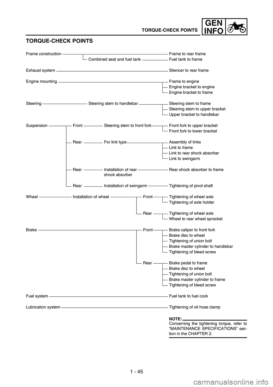
TORQUE-CHECK POINTS
Frame construction Frame to rear frame
Combined seat and fuel tank Fuel tank to frame
Exhaust system Silencer to rear frame
Engine mounting Frame to engine
Engine bracket to engine
Engine bracket to frame
Steering Steering stem to handlebar Steering stem to frame
Steering stem to upper bracket
Upper bracket to handlebar
Suspension Front Steering stem to front fork Front fork to upper bracket
Front fork to lower bracket
Rear For link type Assembly of links
Link to frame
Link to rear shock absorber
Link to swingarm
Rear Installation of rear
shock absorberRear shock absorber to frame
Rear Installation of swingarm Tightening of pivot shaft
Wheel Installation of wheel Front Tightening of wheel axle
Tightening of axle holder
Rear Tightening of wheel axle
Wheel to rear wheel sprocket
Brake Front Brake caliper to front fork
Brake disc to wheel
Tightening of union bolt
Brake master cylinder to handlebar
Tightening of bleed screw
Rear Brake pedal to frame
Brake disc to wheel
Tightening of union bolt
Brake master cylinder to frame
Tightening of bleed screw
Fuel system Fuel tank to fuel cock
Lubrication system Tightening of oil hose clamp
NOTE:Concerning the tightening torque, refer to
“MAINTENANCE SPECIFICATIONS” sec-
tion in the CHAPTER 2.
TORQUE-CHECK POINTS