engine YAMAHA WR 250F 2004 Owner's Manual
[x] Cancel search | Manufacturer: YAMAHA, Model Year: 2004, Model line: WR 250F, Model: YAMAHA WR 250F 2004Pages: 864, PDF Size: 22.07 MB
Page 76 of 864
1 - 51
GEN
INFO
EC1B0000
CLEANING AND
STORAGE
EC1B1000CLEANING
Frequent cleaning of your machine
will enhance its appearance, main-
tain good overall performance, and
extend the life of many components.
1. Before washing the machine,
block off the end of the exhaust
pipe to prevent water from enter-
ing. A plastic bag secured with a
rubber band may be used for this
purpose.
2. If the engine is excessively
greasy, apply some degreaser to
it with a paint brush. Do not
apply degreaser to the chain,
sprockets, or wheel axles.
3. Rinse the dirt and degreaser off
with a garden hose; use only
enough pressure to do the job.
CAUTION:
Excessive hose pressure may
cause water seepage and contami-
nation of wheel bearings, front
forks, brakes and transmission
seals. Many expensive repair bills
have resulted from improper high
pressure detergent applications
such as those available in coin-
operated car washers.
4. After the majority of the dirt has
been hosed off, wash all sur-
faces with warm water and a
mild detergent. Use an old tooth-
brush to clean hard-to-reach
places.
5. Rinse the machine off immedi-
ately with clean water, and dry
all surfaces with a soft towel or
cloth.
6. Immediately after washing,
remove excess water from the
chain with a paper towel and
lubricate the chain to prevent
rust.
7. Clean the seat with a vinyl uphol-
stery cleaner to keep the cover
pliable and glossy.
8. Automotive wax may be applied
to all painted or chromed sur-
faces. Avoid combination
cleaner-waxes, as they may con-
tain abrasives.
9. After completing the above, start
the engine and allow it to idle for
several minutes.
NETTOYAGE ET
RANGEMENT
NETTOYAGE
Un nettoyage fréquent de la machine
améliorera son aspect, maintiendra ses
bonnes performances et augmentera la
durée de service de bon nombre de ses
composants.
1. Avant de laver la moto, boucher la
sortie du pot d’échappement pour
éviter toute pénétration d’eau. Un
sachet en plastique retenu par un
élastique fera l’affaire.
2. Si le moteur est fortement encrassé,
appliquer un peu de dégraissant au
pinceau. Eviter tout contact avec la
chaîne, ses pignons et les axes de
roue.
3. Rincer la boue et le dégraissant au
tuyau d’arrosage, en utilisant juste
la pression suffisante.
ATTENTION:
Une pression excessive risque de pro-
voquer des infiltrations d’eau dans les
roulements des roues, la fourche
avant, des freins et les joints de la
transmission. Noter que bien des notes
de réparation onéreuses ont résulté de
l’emploi abusif des vaporisateurs de
détergent à haute pression, tels que
ceux qui équipent les laveries automa-
tiques de voitures.
4. Après avoir chassé la majeure partie
de la boue, laver toutes les surfaces
avec de l’eau chaude et un détergent
neutre. Utiliser une vieille brosse à
dents pour atteindre les endroits dif-
ficiles d’accès.
5. Rincer immédiatement l’engin avec
de l’eau propre et sécher toutes les
surfaces avec un chiffon doux.
6. Immédiatement après le lavage, éli-
miner l’excès d’eau de la chaîne
avec des mouchoirs en papier et
lubrifier la chaîne pour éviter
qu’elle ne rouille.
7. Nettoyer la selle avec un produit
pour meubles rembourrés pour que
sa housse reste souple et brillante.
8. Un encaustique pour automobile
peut être appliqué sur toutes les sur-
faces peintes et chromées. Eviter les
liquides de nettoyage à encaustique,
car ils contiennent de l’abrasif.
9. Les opérations ci-dessus terminées,
lancer le moteur et le laisser tourner
pendant quelques minutes.
CLEANING AND STORAGE
NETTOYAGE ET RANGEMENT
Page 78 of 864
1 - 53
GEN
INFO
EC1B2001STORAGE
If your machine is to be stored for 60
days or more, some preventive mea-
sures must be taken to avoid deterio-
ration. After cleaning the machine
thoroughly, prepare it for storage as
follows:
1. Drain the fuel tank, fuel lines,
and the carburetor float bowl.
2. Remove the spark plug, pour a
tablespoon of SAE 10W-30
motor oil in the spark plug hole,
and reinstall the plug. With the
engine stop switch pushed in,
kick the engine over several
times to coat the cylinder walls
with oil.
3. Remove the drive chain, clean it
thoroughly with solvent, and
lubricate it. Reinstall the chain or
store it in a plastic bag tied to the
frame.
4. Lubricate all control cables.
5. Block the frame up to raise the
wheels off the ground.
6. Tie a plastic bag over the
exhaust pipe outlet to prevent
moisture from entering.
7. If the machine is to be stored in a
humid or salt-air environment,
coat all exposed metal surfaces
with a film of light oil. Do not
apply oil to rubber parts or the
seat cover.
NOTE:Make any necessary repairs before
the machine is stored.RANGEMENT
Si l’on remise la machine pour 60 jours
ou plus, il faut prendre des mesures de
conservation pour éviter sa détérioration.
Après un nettoyage soigné, préparer la
machine de la manière suivante:
1. Vider le réservoir, les conduites
d’essence et la cuve du carburateur.
2. Déposer la bougie, verser une
cuillère à soupe d’huile moteur SAE
10W-30 dans le trou de bougie, et la
remettre en place. Coupe-circuit à la
position arrêt, donner plusieurs
coups de kick pour enduire le cylin-
dre d’huile.
3. Déposer la chaîne, la nettoyer soi-
gneusement au dissolvant et lubri-
fier. Remonter la chaîne ou la
ranger dans un sachet plastique
fermé fixé au cadre.
4. Lubrifier tous les câbles de com-
mande.
5. Mettre le cadre sur plots pour soule-
ver les roues du sol.
6. Fixer un sachet plastique sur la sor-
tie du pot d’échappement pour évi-
ter l’introduction d’humidité.
7. Si la machine est placée dans une
atmosphère humide ou marine,
enduire toutes les surfaces métalli-
ques nues d’une fine couche
d’huile. Ne pas appliquer d’huile
sur les parties en caoutchouc ou sur
la selle.
N.B.:
Avant de ranger la machine, effectuer
toutes les réparations nécessaires.
CLEANING AND STORAGE
NETTOYAGE ET RANGEMENT
Page 80 of 864
GENERAL SPECIFICATIONS
2 - 1
SPEC
EC200000
SPECIFICATIONS
EC211000
GENERAL SPECIFICATIONS
Model name: WR250FS (USA)
WR250F (EUROPE)
WR250F(S) (CDN, AUS, NZ, ZA)
Model code number: 5UM5 (USA)
5UM6 (EUROPE)
5UM7 (CDN, AUS, NZ, ZA)
Dimensions:
Overall length 2,165 mm (85.2 in)
Overall width 827 mm (32.6 in)
Overall height 1,303 mm (51.3 in)
Seat height 998 mm (39.3 in)
Wheelbase 1,475 mm (58.1 in)
Minimum ground clearance 382 mm (15.0 in)
Dry weight:
Without oil and fuel 105.5 kg (232.6 lb)
Engine:
Engine type Liquid cooled 4-stroke, DOHC
Cylinder arrangement Single cylinder, forward inclined
Displacement 249 cm
3 (8.76 Imp oz, 8.42 US oz)
Bore × stroke 77.0 × 53.6 mm (3.03 × 2.11 in)
Compression ratio 12.5 : 1
Starting system Kick and electric starter
Lubrication system: Dry sump
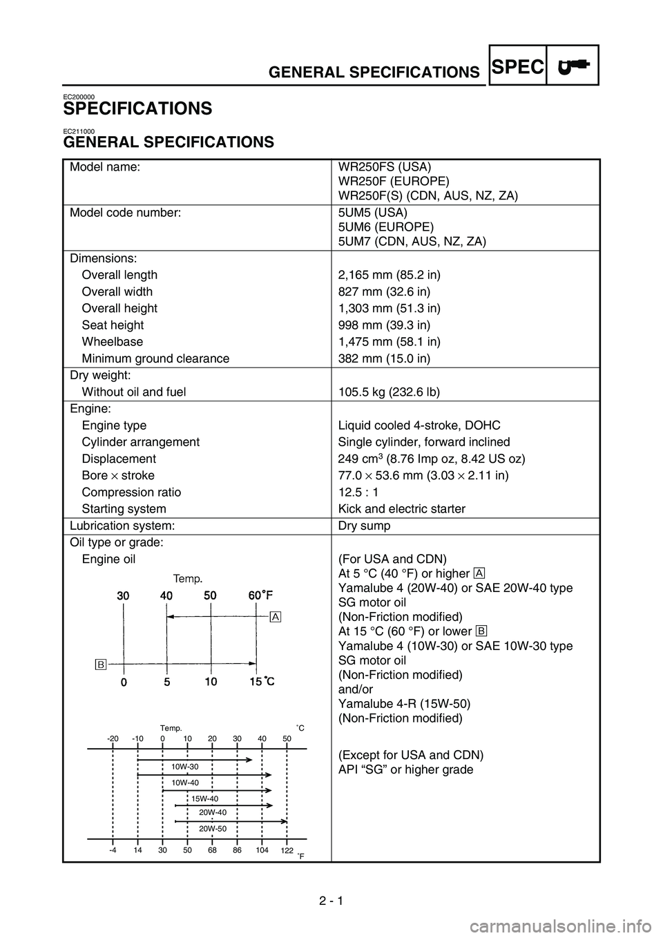
Oil type or grade:
Engine oil (For USA and CDN)
At 5 °C (40 °F) or higher È
Yamalube 4 (20W-40) or SAE 20W-40 type
SG motor oil
(Non-Friction modified)
At 15 °C (60 °F) or lower É
Yamalube 4 (10W-30) or SAE 10W-30 type
SG motor oil
(Non-Friction modified)
and/or
Yamalube 4-R (15W-50)
(Non-Friction modified)
(Except for USA and CDN)
API “SG” or higher grade
-20
-4-10
140
3010
5020
6830
8640 50
104
122˚CTemp.
˚F
10W-30
10W-40
20W-40
20W-50
15W-40
2
Page 81 of 864
GENERAL SPECIFICATIONS
2 - 2
SPEC
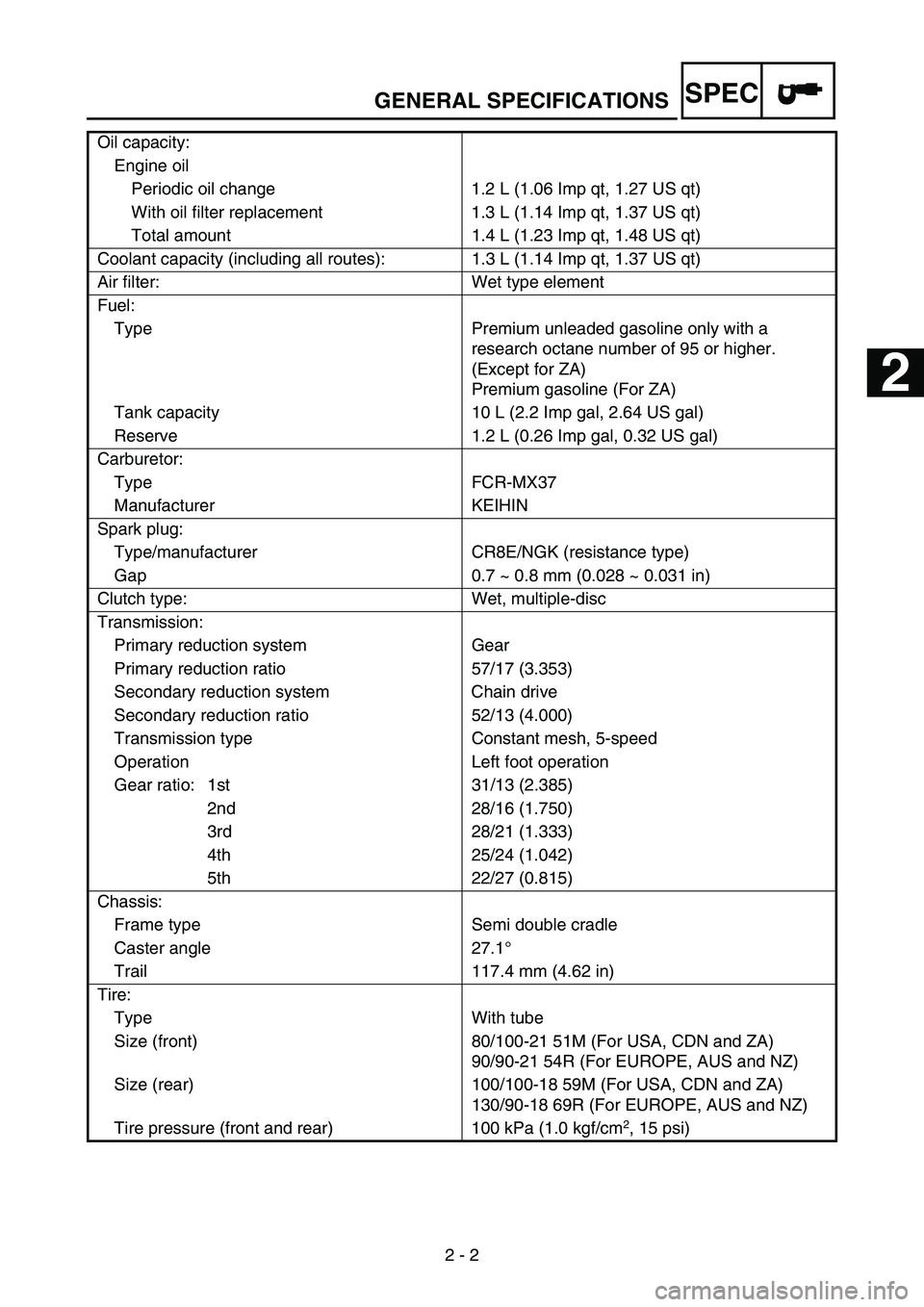
Oil capacity:
Engine oil
Periodic oil change 1.2 L (1.06 Imp qt, 1.27 US qt)
With oil filter replacement 1.3 L (1.14 Imp qt, 1.37 US qt)
Total amount 1.4 L (1.23 Imp qt, 1.48 US qt)
Coolant capacity (including all routes): 1.3 L (1.14 Imp qt, 1.37 US qt)
Air filter: Wet type element
Fuel:
Type Premium unleaded gasoline only with a
research octane number of 95 or higher.
(Except for ZA)
Premium gasoline (For ZA)
Tank capacity 10 L (2.2 Imp gal, 2.64 US gal)
Reserve 1.2 L (0.26 Imp gal, 0.32 US gal)
Carburetor:
Type FCR-MX37
Manufacturer KEIHIN
Spark plug:
Type/manufacturer CR8E/NGK (resistance type)
Gap 0.7 ~ 0.8 mm (0.028 ~ 0.031 in)
Clutch type: Wet, multiple-disc
Transmission:
Primary reduction system Gear
Primary reduction ratio 57/17 (3.353)
Secondary reduction system Chain drive
Secondary reduction ratio 52/13 (4.000)
Transmission type Constant mesh, 5-speed
Operation Left foot operation
Gear ratio: 1st 31/13 (2.385)
2nd 28/16 (1.750)
3rd 28/21 (1.333)
4th 25/24 (1.042)
5th 22/27 (0.815)
Chassis:
Frame type Semi double cradle
Caster angle 27.1°
Trail 117.4 mm (4.62 in)
Tire:
Type With tube
Size (front) 80/100-21 51M (For USA, CDN and ZA)
90/90-21 54R (For EUROPE, AUS and NZ)
Size (rear) 100/100-18 59M (For USA, CDN and ZA)
130/90-18 69R (For EUROPE, AUS and NZ)
Tire pressure (front and rear) 100 kPa (1.0 kgf/cm
2, 15 psi)
1
2
3
4
5
6
7
Page 83 of 864
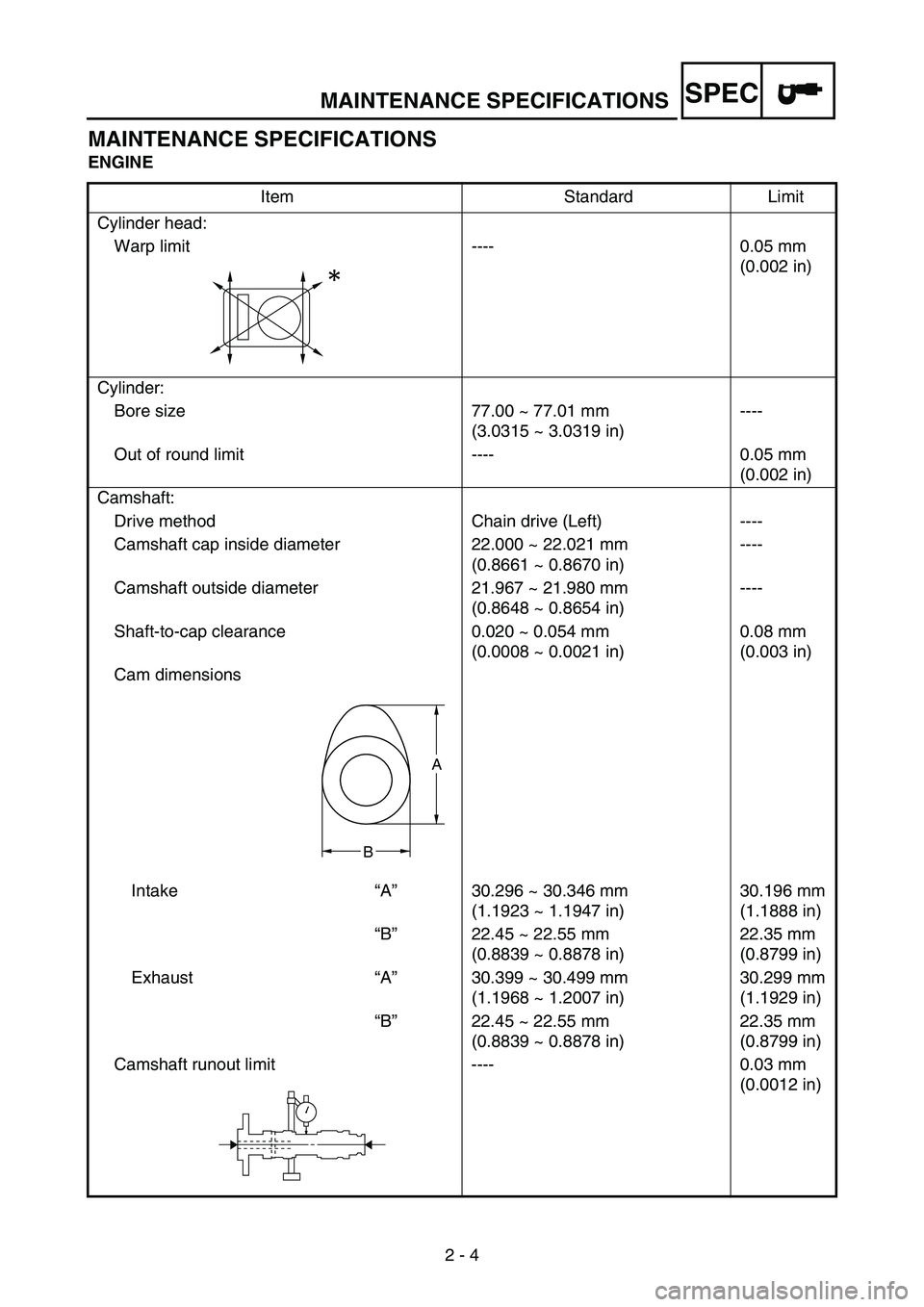
MAINTENANCE SPECIFICATIONS
2 - 4
SPEC
MAINTENANCE SPECIFICATIONS
ENGINE
Item Standard Limit
Cylinder head:
Warp limit ---- 0.05 mm
(0.002 in)
Cylinder:
Bore size 77.00 ~ 77.01 mm
(3.0315 ~ 3.0319 in)----
Out of round limit ---- 0.05 mm
(0.002 in)
Camshaft:
Drive method Chain drive (Left) ----
Camshaft cap inside diameter 22.000 ~ 22.021 mm
(0.8661 ~ 0.8670 in)----
Camshaft outside diameter 21.967 ~ 21.980 mm
(0.8648 ~ 0.8654 in)----
Shaft-to-cap clearance 0.020 ~ 0.054 mm
(0.0008 ~ 0.0021 in)0.08 mm
(0.003 in)
Cam dimensions
Intake“A”30.296 ~ 30.346 mm
(1.1923 ~ 1.1947 in)30.196 mm
(1.1888 in)
“B”22.45 ~ 22.55 mm
(0.8839 ~ 0.8878 in)22.35 mm
(0.8799 in)
Exhaust“A”30.399 ~ 30.499 mm
(1.1968 ~ 1.2007 in)30.299 mm
(1.1929 in)
“B”22.45 ~ 22.55 mm
(0.8839 ~ 0.8878 in)22.35 mm
(0.8799 in)
Camshaft runout limit ---- 0.03 mm
(0.0012 in)
A
B
Page 87 of 864
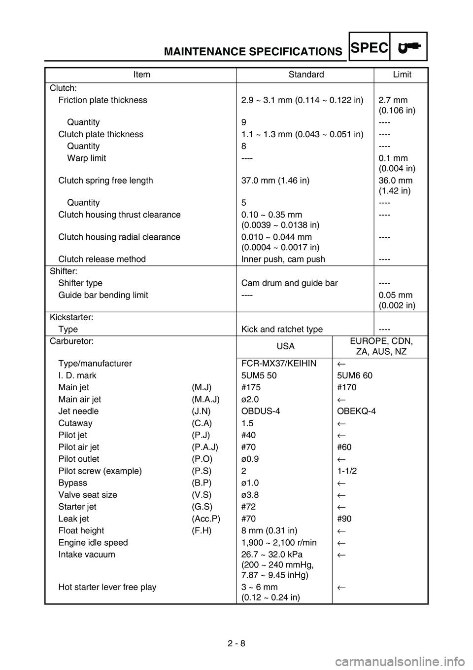
MAINTENANCE SPECIFICATIONS
2 - 8
SPEC
Clutch:
Friction plate thickness 2.9 ~ 3.1 mm (0.114 ~ 0.122 in) 2.7 mm
(0.106 in)
Quantity 9 ----
Clutch plate thickness 1.1 ~ 1.3 mm (0.043 ~ 0.051 in) ----
Quantity 8 ----
Warp limit ---- 0.1 mm
(0.004 in)
Clutch spring free length 37.0 mm (1.46 in) 36.0 mm
(1.42 in)
Quantity 5 ----
Clutch housing thrust clearance 0.10 ~ 0.35 mm
(0.0039 ~ 0.0138 in)----
Clutch housing radial clearance 0.010 ~ 0.044 mm
(0.0004 ~ 0.0017 in)----
Clutch release method Inner push, cam push ----
Shifter:
Shifter type Cam drum and guide bar ----
Guide bar bending limit ---- 0.05 mm
(0.002 in)
Kickstarter:
Type Kick and ratchet type ----
Carburetor:
USAEUROPE, CDN,
ZA, AUS, NZ
Type/manufacturer FCR-MX37/KEIHIN←
I. D. mark 5UM5 50 5UM6 60
Main jet (M.J) #175 #170
Main air jet (M.A.J)ø2.0←
Jet needle (J.N) OBDUS-4 OBEKQ-4
Cutaway (C.A) 1.5←
Pilot jet (P.J) #40←
Pilot air jet (P.A.J) #70 #60
Pilot outlet (P.O)ø0.9←
Pilot screw (example) (P.S) 2 1-1/2
Bypass (B.P)ø1.0←
Valve seat size (V.S)ø3.8←
Starter jet (G.S) #72←
Leak jet (Acc.P) #70 #90
Float height (F.H) 8 mm (0.31 in)←
Engine idle speed 1,900 ~ 2,100 r/min←
Intake vacuum 26.7 ~ 32.0 kPa
(200 ~ 240 mmHg,
7.87 ~ 9.45 inHg)←
Hot starter lever free play 3 ~ 6 mm
(0.12 ~ 0.24 in)← Item Standard Limit
Page 94 of 864
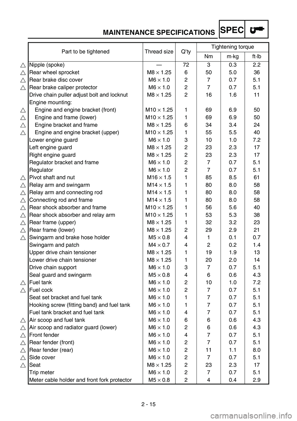
MAINTENANCE SPECIFICATIONS
2 - 15
SPEC
Part to be tightened Thread size Q’tyTightening torque
Nm m·kg ft·lb
Nipple (spoke)—72 3 0.3 2.2
Rear wheel sprocket M8 × 1.25 6 50 5.0 36
Rear brake disc cover M6 × 1.0 2 7 0.7 5.1
Rear brake caliper protector M6 × 1.0 2 7 0.7 5.1
Drive chain puller adjust bolt and locknut M8 × 1.25 2 16 1.6 11
Engine mounting:
Engine and engine bracket (front) M10 × 1.25 1 69 6.9 50
Engine and frame (lower) M10 × 1.25 1 69 6.9 50
Engine bracket and frame M8 × 1.25 6 34 3.4 24
Engine and engine bracket (upper) M10 × 1.25 1 55 5.5 40
Lower engine guard M6 × 1.0 3 10 1.0 7.2
Left engine guard M8 × 1.25 2 23 2.3 17
Right engine guard M8 × 1.25 2 23 2.3 17
Regulator bracket and frame M6 × 1.0 2 7 0.7 5.1
Regulator M6 × 1.0 2 7 0.7 5.1
Pivot shaft and nut M16 × 1.5 1 85 8.5 61
Relay arm and swingarm M14 × 1.5 1 80 8.0 58
Relay arm and connecting rod M14 × 1.5 1 80 8.0 58
Connecting rod and frame M14 × 1.5 1 80 8.0 58
Rear shock absorber and frame M10 × 1.25 1 56 5.6 40
Rear shock absorber and relay arm M10 × 1.25 1 53 5.3 38
Rear frame (upper) M8 × 1.25 1 32 3.2 23
Rear frame (lower) M8 × 1.25 2 29 2.9 21
Swingarm and brake hose holder M5 × 0.8 4 1 0.1 0.7
Swingarm and patch M4 × 0.7 4 2 0.2 1.4
Upper drive chain tensioner M8 × 1.25 1 19 1.9 13
Lower drive chain tensioner M8 × 1.25 1 20 2.0 14
Drive chain support M6 × 1.0 3 7 0.7 5.1
Seal guard and swingarm M5 × 0.8 4 6 0.6 4.3
Fuel tank M6 × 1.0 2 10 1.0 7.2
Fuel cock M6 × 1.0 2 7 0.7 5.1
Seat set bracket and fuel tank M6 × 1.0 1 7 0.7 5.1
Hooking screw (fitting band) and fuel tank M6 × 1.0 1 7 0.7 5.1
Fuel tank bracket and fuel tank M6 × 1.0 4 7 0.7 5.1
Air scoop and fuel tank M6 × 1.0 6 6 0.6 4.3
Air scoop and radiator guard (lower) M6 × 1.0 2 6 0.6 4.3
Front fender M6 × 1.0 4 7 0.7 5.1
Rear fender (front) M6 × 1.0 2 7 0.7 5.1
Rear fender (rear) M6 × 1.0 2 11 1.1 8.0
Side cover M6 × 1.0 2 7 0.7 5.1
Seat M8 × 1.25 2 23 2.3 17
Trip meter M6 × 1.0 2 7 0.7 5.1
Meter cable holder and front fork protector M5 × 0.8 2 4 0.4 2.9
Page 98 of 864
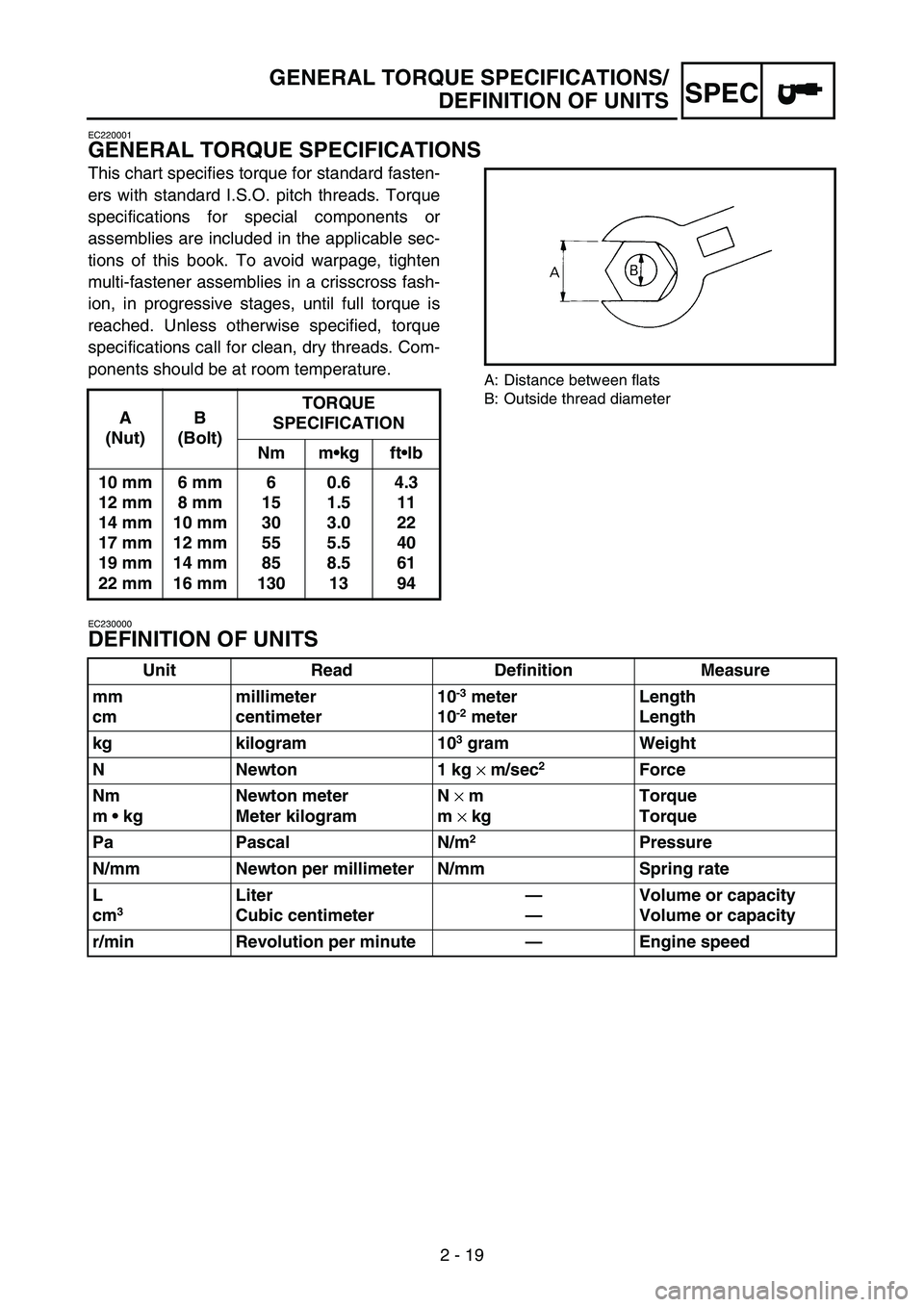
2 - 19
GENERAL TORQUE SPECIFICATIONS/
DEFINITION OF UNITS
SPEC
EC220001
GENERAL TORQUE SPECIFICATIONS
This chart specifies torque for standard fasten-
ers with standard I.S.O. pitch threads. Torque
specifications for special components or
assemblies are included in the applicable sec-
tions of this book. To avoid warpage, tighten
multi-fastener assemblies in a crisscross fash-
ion, in progressive stages, until full torque is
reached. Unless otherwise specified, torque
specifications call for clean, dry threads. Com-
ponents should be at room temperature.
A: Distance between flats
B: Outside thread diameter
EC230000
DEFINITION OF UNITS
A
(Nut)B
(Bolt)TORQUE
SPECIFICATION
Nm mkg ftlb
10 mm
12 mm
14 mm
17 mm
19 mm
22 mm6 mm
8 mm
10 mm
12 mm
14 mm
16 mm6
15
30
55
85
1300.6
1.5
3.0
5.5
8.5
134.3
11
22
40
61
94
Unit Read Definition Measure
mm
cmmillimeter
centimeter10
-3 meter
10-2 meterLength
Length
kg kilogram 10
3 gram Weight
N Newton 1 kg
× m/sec
2 Force
Nm
m kgNewton meter
Meter kilogramN
× m
m
× kgTorque
Torque
Pa Pascal N/m
2Pressure
N/mm Newton per millimeter N/mm Spring rate
L
cm
3 Liter
Cubic centimeter—
—Volume or capacity
Volume or capacity
r/min Revolution per minute—Engine speed
Page 190 of 864
SPEC
2 - 111
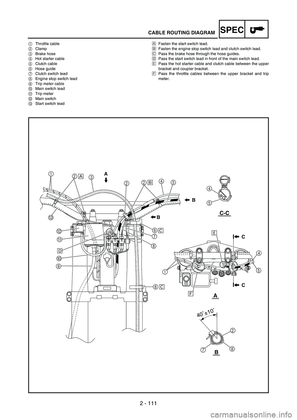
CABLE ROUTING DIAGRAM
1Throttle cable
2Clamp
3Brake hose
4Hot starter cable
5Clutch cable
6Hose guide
7Clutch switch lead
8Engine stop switch lead
9Trip meter cable
0Main switch lead
ATrip meter
BMain switch
CStart switch leadÈFasten the start switch lead.
ÉFasten the engine stop switch lead and clutch switch lead.
ÊPass the brake hose through the hose guides.
ËPass the start switch lead in front of the main switch lead.
ÌPass the hot starter cable and clutch cable between the upper
bracket and coupler bracket.
ÍPass the throttle cables between the upper bracket and trip
meter.
A
A
B
C-CB
B
C
C
1
2
3
224
5
C
B
A
0
96
7
8
64
5
4
15
2
8
7
40˚±10˚
ËÈ
É
Ê
Ê
ÍÌ
Page 192 of 864
3 - 1
INSP
ADJ
MAINTENANCE INTERVALS
EC300000
REGULAR INSPECTION AND ADJUSTMENTS
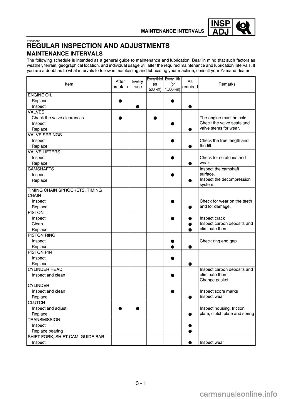
MAINTENANCE INTERVALS
The following schedule is intended as a general guide to maintenance and lubrication. Bear in mind that such factors as
weather, terrain, geographical location, and individual usage will alter the required maintenance and lubrication intervals. If
you are a doubt as to what intervals to follow in maintaining and lubricating your machine, consult your Yamaha dealer.
ItemAfter
break-inEvery
race
Every third
(or
500 km)Every fifth
(or
1,000 km)As
requiredRemarks
ENGINE OIL
Replace
Inspect
VALVES
Check the valve clearances The engine must be cold.
Check the valve seats and
valve stems for wear. Inspect
Replace
VALVE SPRINGS
InspectCheck the free length and
the tilt.
Replace
VALVE LIFTERS
InspectCheck for scratches and
wear.
Replace
CAMSHAFTSInspect the camshaft
surface.
Inspect the decompression
system. Inspect
Replace
TIMING CHAIN SPROCKETS, TIMING
CHAIN
InspectCheck for wear on the teeth
and for damage.
Replace
PISTON
InspectInspect crack
Inspect carbon deposits and
eliminate them. Clean
Replace
PISTON RING
InspectCheck ring end gap
Replace
PISTON PIN
Inspect
Replace
CYLINDER HEADInspect carbon deposits and
eliminate them.
Change gasket Inspect and clean
CYLINDER
Inspect and clean Inspect score marks
Inspect wear
Replace
CLUTCH
Inspect and adjust Inspect housing, friction
plate, clutch plate and spring
Replace
TRANSMISSION
Inspect
Replace bearing
SHIFT FORK, SHIFT CAM, GUIDE BAR
InspectInspect wear