YAMAHA WR 250F 2004 Owners Manual
Manufacturer: YAMAHA, Model Year: 2004, Model line: WR 250F, Model: YAMAHA WR 250F 2004Pages: 864, PDF Size: 22.07 MB
Page 531 of 864
![YAMAHA WR 250F 2004 Owners Manual 4 - 206
ENG
13. Montieren:
Motorschutz
1
Klammer
2
Unterlegscheibe
3
Schraube
[Motorschutz (vorne)]
4
Schraube
[Motorschutz (hinten)]
5
Zylinderkopf-Lüftungs-
schlauch
6
T R..23 N YAMAHA WR 250F 2004 Owners Manual 4 - 206
ENG
13. Montieren:
Motorschutz
1
Klammer
2
Unterlegscheibe
3
Schraube
[Motorschutz (vorne)]
4
Schraube
[Motorschutz (hinten)]
5
Zylinderkopf-Lüftungs-
schlauch
6
T R..23 N](/img/51/52336/w960_52336-530.png)
4 - 206
ENG
13. Montieren:
Motorschutz
1
Klammer
2
Unterlegscheibe
3
Schraube
[Motorschutz (vorne)]
4
Schraube
[Motorschutz (hinten)]
5
Zylinderkopf-Lüftungs-
schlauch
6
T R..23 Nm (2,3 m · kg, 17 ft · lb)
T R..23 Nm (2,3 m · kg, 17 ft · lb)
14. Anschließen:
AC-Magnetzünderleitung
Siehe unter “KABELFÜH-
RUNG” in KAPITEL 2.
15. Montieren:
Fußschalthebel
1
Schraube (Fußschalthebel)
HINWEIS:
Beim Einbau des Fußschalthebel an
der Schaltwelle sicherstellen, daß die
Mitte des Fußschalthebel etwa 1 mm
(0,04 in)
a über der Oberkante der
Fußraste ist.
T R..12 Nm (1,2 m · kg, 8,7 ft · lb)
13. Installare:
Protezione motore 1
Morsetto 2
Rondella 3
Bullone
[protezione motore (davanti)] 4
Bullone
[protezione motore (dietro)] 5
Sfiatatoio testata cilindro 6
T R..23 Nm (2,3 m · kg, 17 ft · lb)
T R..23 Nm (2,3 m · kg, 17 ft · lb)
14. Collegare:
Cavo del magnete CA
Fare riferimento al paragrafo
“SCHEMA DEL PERCORSO
DEI CAVI” nel CAPITOLO 2.
15. Installare:
Pedale del cambio 1
Bullone (pedale del cambio)
NOTA:
Quando si installa il pedale del cambio
sull’albero del cambio, assicurarsi che il
centro del pedale del cambio sia circa
1 mm (0,04 in) a al di sopra del poggia-
piedi.
T R..12 Nm (1,2 m · kg, 8,7 ft · lb)
13. Instalar:
Protector del motor
1
Abrazadera
2
Arandela
3
Perno [protector del motor
(delantero)]
4
Perno [protector del motor
(trasero)]
5
Tubo respiradero de la culata
6
T R..23 Nm (2,3 m · kg, 17 ft · lb)
T R..23 Nm (2,3 m · kg, 17 ft · lb)
14. Conectar:
Cable del magneto de CA
Consulte el apartado
“DIAGRAMA DE RUTA DE
CABLES” del CAPÍTULO 2.
15. Instalar:
Pedal de cambios
1
Perno (pedal de cambios)
NOTA:
Cuando instale el pedal de cambios
en el eje de cambios, asegúrese de
que el centro del pedal de cambios
esté aproximadamente 1 mm
(0,04 in)
a por encima de la parte
superior del estribo.
T R..12 Nm (1,2 m · kg, 8,7 ft · lb)
AC-MAGNETZÜNDER UND STARTERKUPPLUNG
MAGNETE CA E FRIZIONE DELLO STARTER
MAGNETO DE CA Y EMBRAGUE DEL ARRANCADOR
Page 532 of 864
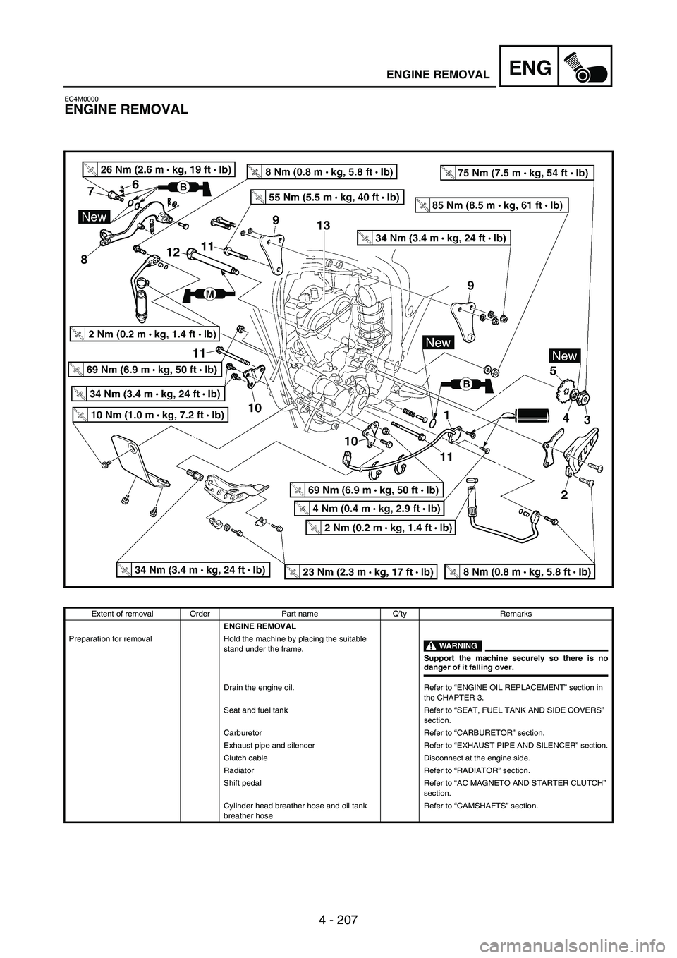
4 - 207
ENGENGINE REMOVAL
EC4M0000
ENGINE REMOVAL
Extent of removal Order Part name Q’ty Remarks
ENGINE REMOVAL
Preparation for removal Hold the machine by placing the suitable
stand under the frame.
WARNING
Support the machine securely so there is nodanger of it falling over.
Drain the engine oil. Refer to “ENGINE OIL REPLACEMENT” section in
the CHAPTER 3.
Seat and fuel tank Refer to “SEAT, FUEL TANK AND SIDE COVERS”
section.
Carburetor Refer to “CARBURETOR” section.
Exhaust pipe and silencer Refer to “EXHAUST PIPE AND SILENCER” section.
Clutch cable Disconnect at the engine side.
Radiator Refer to “RADIATOR” section.
Shift pedal Refer to “AC MAGNETO AND STARTER CLUTCH”
section.
Cylinder head breather hose and oil tank
breather hoseRefer to “CAMSHAFTS” section.
Page 533 of 864
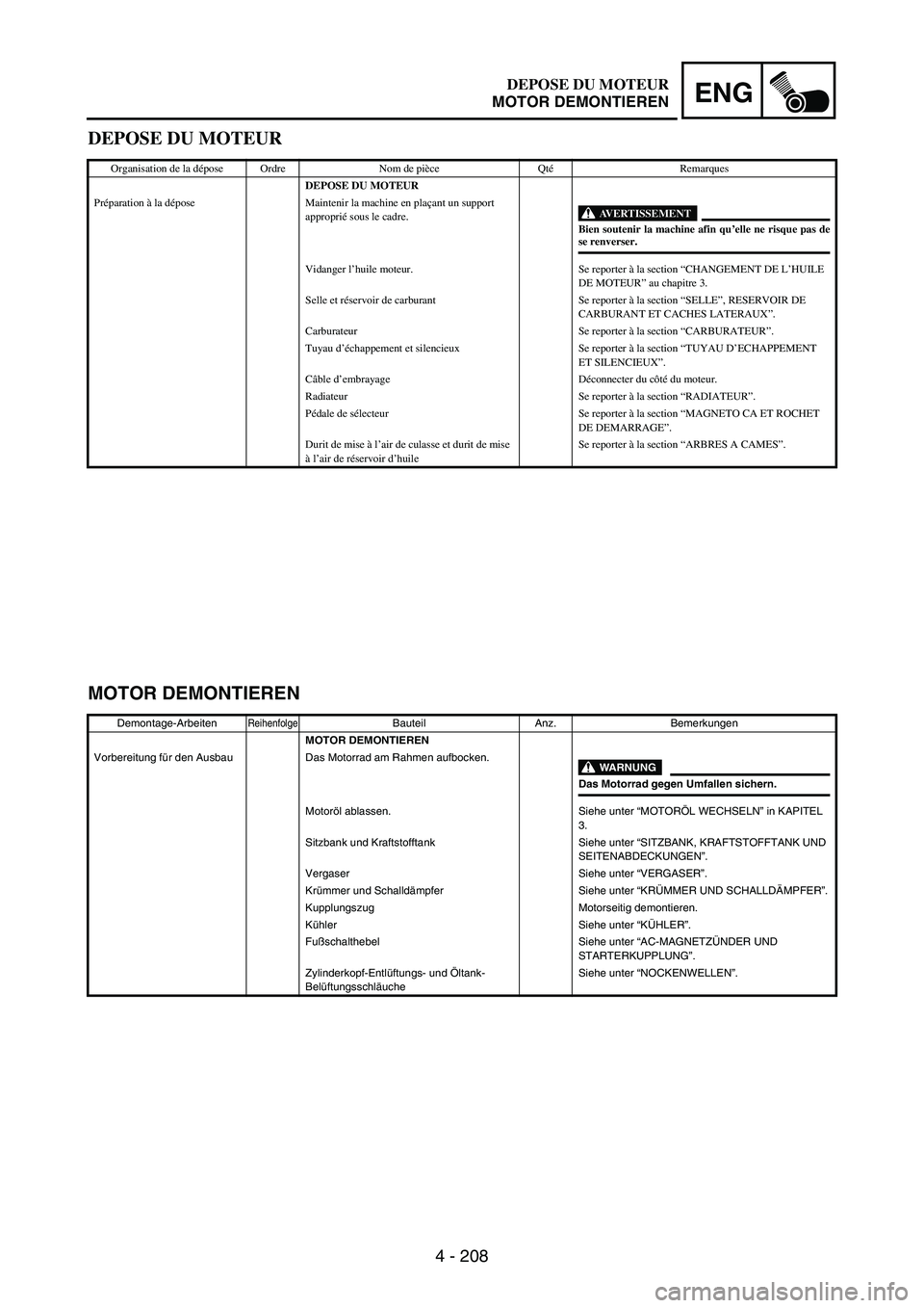
4 - 208
ENG
DEPOSE DU MOTEUR
Organisation de la dépose Ordre Nom de pièce QtéRemarques
DEPOSE DU MOTEUR
Préparation à la dépose Maintenir la machine en plaçant un support
approprié sous le cadre.
AVERTISSEMENTBien soutenir la machine afin qu’elle ne risque pas dese renverser.
Vidanger l’huile moteur. Se reporter à la section “CHANGEMENT DE L’HUILE
DE MOTEUR” au chapitre 3.
Selle et réservoir de carburant Se reporter à la section “SELLE”, RESERVOIR DE
CARBURANT ET CACHES LATERAUX”.
Carburateur Se reporter à la section “CARBURATEUR”.
Tuyau d’échappement et silencieux Se reporter à la section “TUYAU D’ECHAPPEMENT
ET SILENCIEUX”.
Câble d’embrayage Déconnecter du côté du moteur.
Radiateur Se reporter à la section “RADIATEUR”.
Pédale de sélecteur Se reporter à la section “MAGNETO CA ET ROCHET
DE DEMARRAGE”.
Durit de mise à l’air de culasse et durit de mise
à l’air de réservoir d’huileSe reporter à la section “ARBRES A CAMES”.
MOTOR DEMONTIEREN
Demontage-ArbeitenReihenfolgeBauteil Anz. Bemerkungen
MOTOR DEMONTIEREN
Vorbereitung für den Ausbau Das Motorrad am Rahmen aufbocken.
WARNUNG
Das Motorrad gegen Umfallen sichern.
Motoröl ablassen. Siehe unter “MOTORÖL WECHSELN” in KAPITEL
3.
Sitzbank und Kraftstofftank Siehe unter “SITZBANK, KRAFTSTOFFTANK UND
SEITENABDECKUNGEN”.
Vergaser Siehe unter “VERGASER”.
Krümmer und Schalldämpfer Siehe unter “KRÜMMER UND SCHALLDÄMPFER”.
Kupplungszug Motorseitig demontieren.
Kühler Siehe unter “KÜHLER”.
Fußschalthebel Siehe unter “AC-MAGNETZÜNDER UND
STARTERKUPPLUNG”.
Zylinderkopf-Entlüftungs- und Öltank-
BelüftungsschläucheSiehe unter “NOCKENWELLEN”.
DEPOSE DU MOTEUR
MOTOR DEMONTIEREN
Page 534 of 864
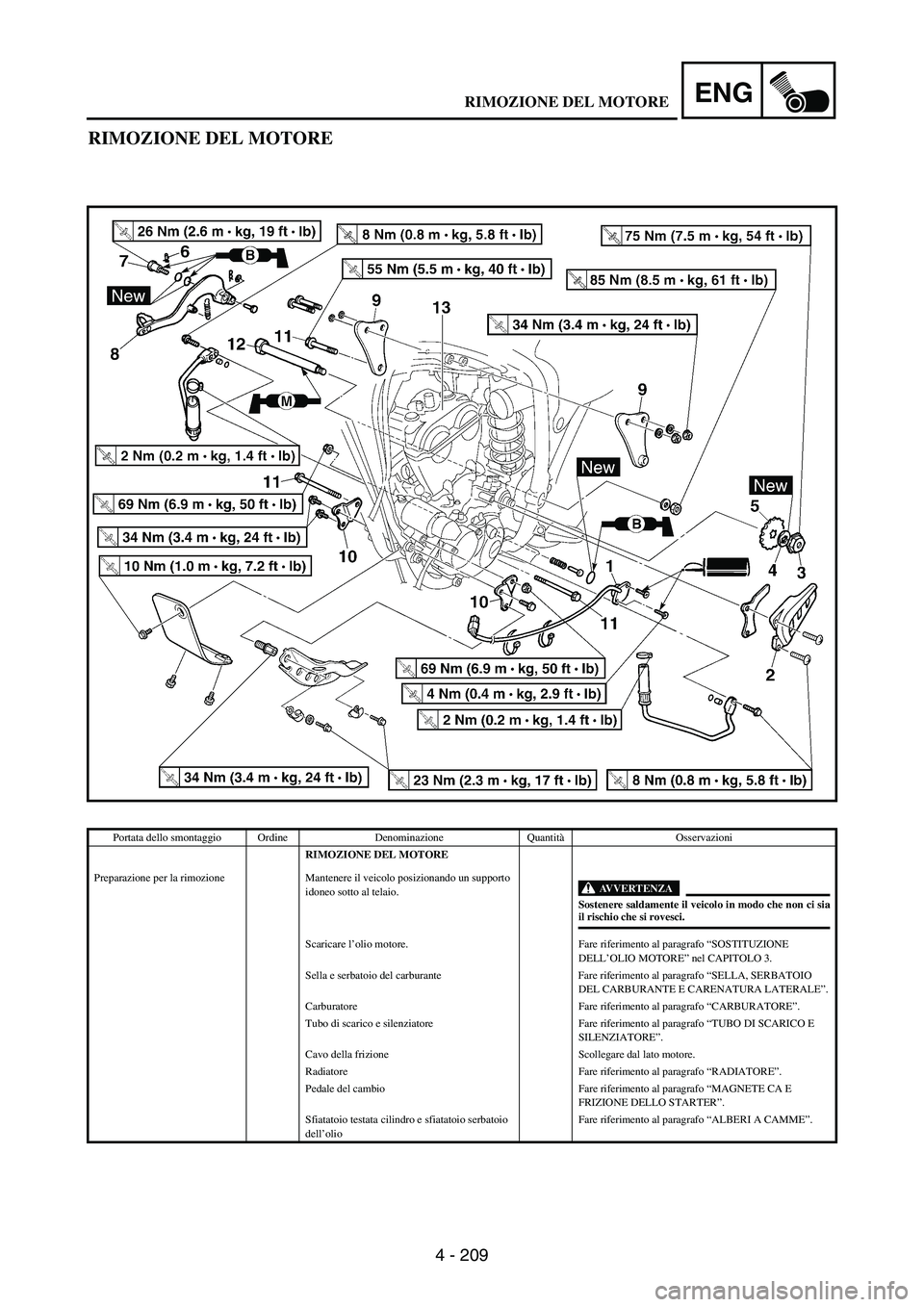
4 - 209
ENG
RIMOZIONE DEL MOTORE
Portata dello smontaggio Ordine Denominazione QuantitàOsservazioni
RIMOZIONE DEL MOTORE
Preparazione per la rimozione Mantenere il veicolo posizionando un supporto
idoneo sotto al telaio.
AVVERTENZA
Sostenere saldamente il veicolo in modo che non ci siail rischio che si rovesci.
Scaricare l’olio motore. Fare riferimento al paragrafo “SOSTITUZIONE
DELL’OLIO MOTORE” nel CAPITOLO 3.
Sella e serbatoio del carburante Fare riferimento al paragrafo “SELLA, SERBATOIO
DEL CARBURANTE E CARENATURA LATERALE”.
Carburatore Fare riferimento al paragrafo “CARBURATORE”.
Tubo di scarico e silenziatore Fare riferimento al paragrafo “TUBO DI SCARICO E
SILENZIATORE”.
Cavo della frizione Scollegare dal lato motore.
Radiatore Fare riferimento al paragrafo “RADIATORE”.
Pedale del cambio Fare riferimento al paragrafo “MAGNETE CA E
FRIZIONE DELLO STARTER”.
Sfiatatoio testata cilindro e sfiatatoio serbatoio
dell’olioFare riferimento al paragrafo “ALBERI A CAMME”.
RIMOZIONE DEL MOTORE
Page 535 of 864
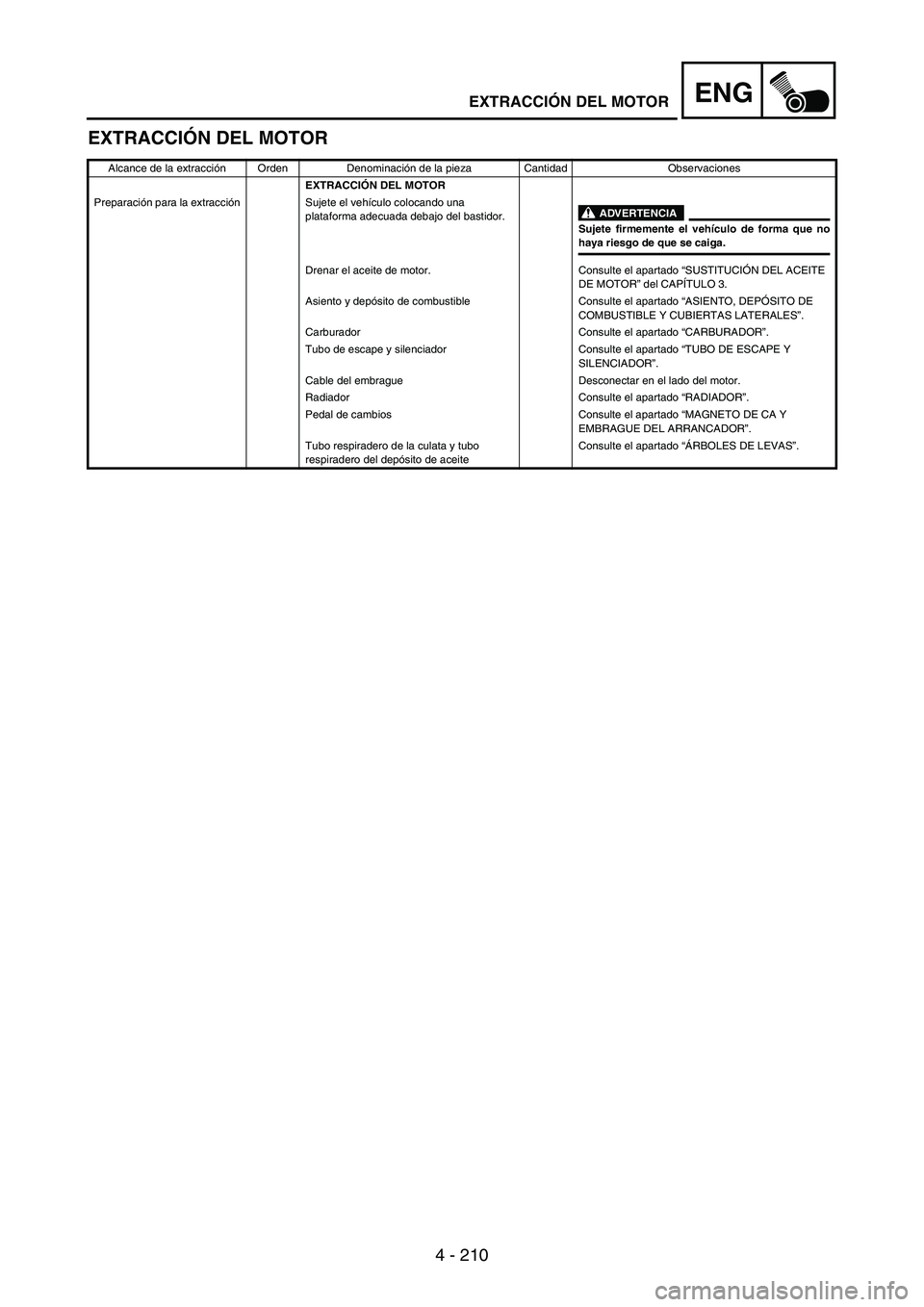
4 - 210
ENG
EXTRACCIÓN DEL MOTOR
Alcance de la extracción Orden Denominación de la pieza Cantidad Observaciones
EXTRACCIÓN DEL MOTOR
Preparación para la extracción Sujete el vehículo colocando una
plataforma adecuada debajo del bastidor.
ADVERTENCIA
Sujete firmemente el vehículo de forma que nohaya riesgo de que se caiga.
Drenar el aceite de motor. Consulte el apartado “SUSTITUCIÓN DEL ACEITE
DE MOTOR” del CAPÍTULO 3.
Asiento y depósito de combustible Consulte el apartado “ASIENTO, DEPÓSITO DE
COMBUSTIBLE Y CUBIERTAS LATERALES”.
Carburador Consulte el apartado “CARBURADOR”.
Tubo de escape y silenciador Consulte el apartado “TUBO DE ESCAPE Y
SILENCIADOR”.
Cable del embrague Desconectar en el lado del motor.
Radiador Consulte el apartado “RADIADOR”.
Pedal de cambios Consulte el apartado “MAGNETO DE CA Y
EMBRAGUE DEL ARRANCADOR”.
Tubo respiradero de la culata y tubo
respiradero del depósito de aceiteConsulte el apartado “ÁRBOLES DE LEVAS”.
EXTRACCIÓN DEL MOTOR
Page 536 of 864
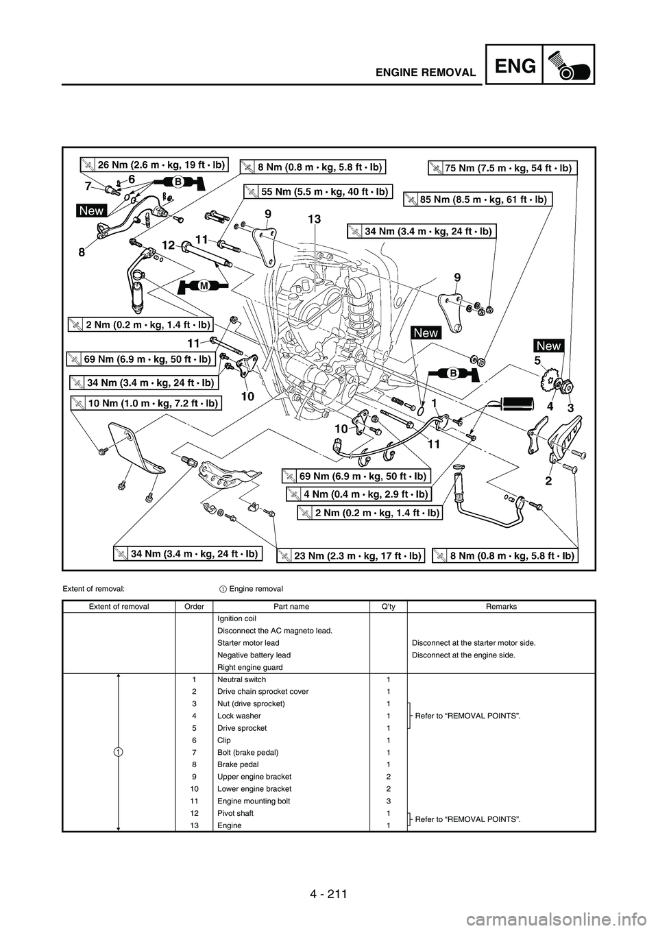
4 - 211
ENGENGINE REMOVAL
Extent of removal:
1 Engine removal
Extent of removal Order Part name Q’ty Remarks
Ignition coil
Disconnect the AC magneto lead.
Starter motor lead Disconnect at the starter motor side.
Negative battery lead Disconnect at the engine side.
Right engine guard
1 Neutral switch 1
2 Drive chain sprocket cover 1
3 Nut (drive sprocket) 1
Refer to “REMOVAL POINTS”. 4 Lock washer 1
5 Drive sprocket 1
6 Clip 1
7 Bolt (brake pedal) 1
8 Brake pedal 1
9 Upper engine bracket 2
10 Lower engine bracket 2
11 Engine mounting bolt 3
12 Pivot shaft 1
Refer to “REMOVAL POINTS”.
13 Engine 1
1
Page 537 of 864
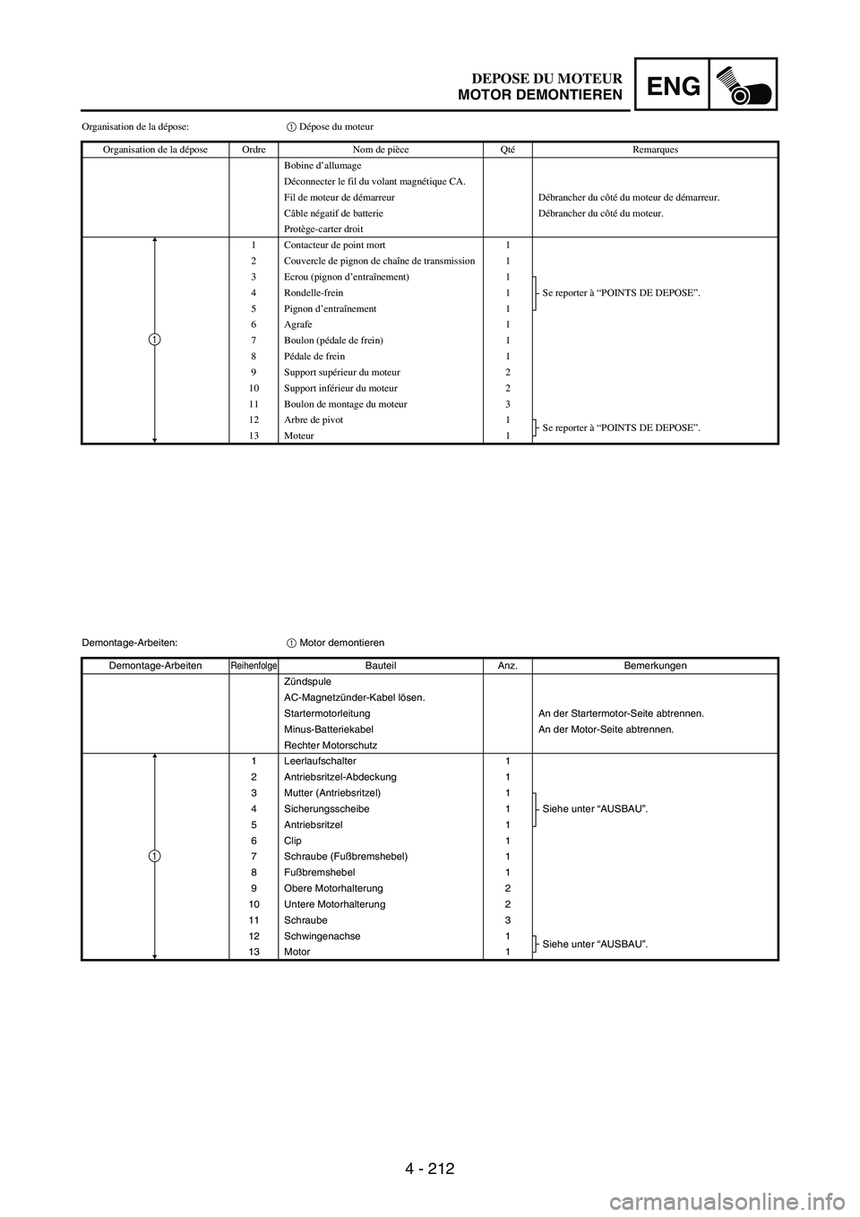
4 - 212
ENG
Organisation de la dépose:1 Dépose du moteur
Organisation de la dépose Ordre Nom de pièce QtéRemarques
Bobine d’allumage
Déconnecter le fil du volant magnétique CA.
Fil de moteur de démarreur Débrancher du côté du moteur de démarreur.
Câble négatif de batterie Débrancher du côté du moteur.
Protège-carter droit
1 Contacteur de point mort 1
2 Couvercle de pignon de chaîne de transmission 1
3 Ecrou (pignon d’entraînement) 1
Se reporter à “POINTS DE DEPOSE”. 4 Rondelle-frein 1
5 Pignon d’entraînement 1
6Agrafe 1
7 Boulon (pédale de frein) 1
8Pédale de frein 1
9 Support supérieur du moteur 2
10 Support inférieur du moteur 2
11 Boulon de montage du moteur 3
12 Arbre de pivot 1
Se reporter à “POINTS DE DEPOSE”.
13 Moteur 1
1
Demontage-Arbeiten:
1 Motor demontieren
Demontage-Arbeiten
ReihenfolgeBauteil Anz. Bemerkungen
Zündspule
AC-Magnetzünder-Kabel lösen.
Startermotorleitung An der Startermotor-Seite abtrennen.
Minus-Batteriekabel An der Motor-Seite abtrennen.
Rechter Motorschutz
1 Leerlaufschalter 1
2 Antriebsritzel-Abdeckung 1
3 Mutter (Antriebsritzel) 1
Siehe unter “AUSBAU”. 4 Sicherungsscheibe 1
5Antriebsritzel 1
6 Clip 1
7 Schraube (Fußbremshebel) 1
8Fußbremshebel 1
9 Obere Motorhalterung 2
10 Untere Motorhalterung 2
11 Schraube 3
12 Schwingenachse 1
Siehe unter “AUSBAU”.
13 Motor 1
1
DEPOSE DU MOTEUR
MOTOR DEMONTIEREN
Page 538 of 864
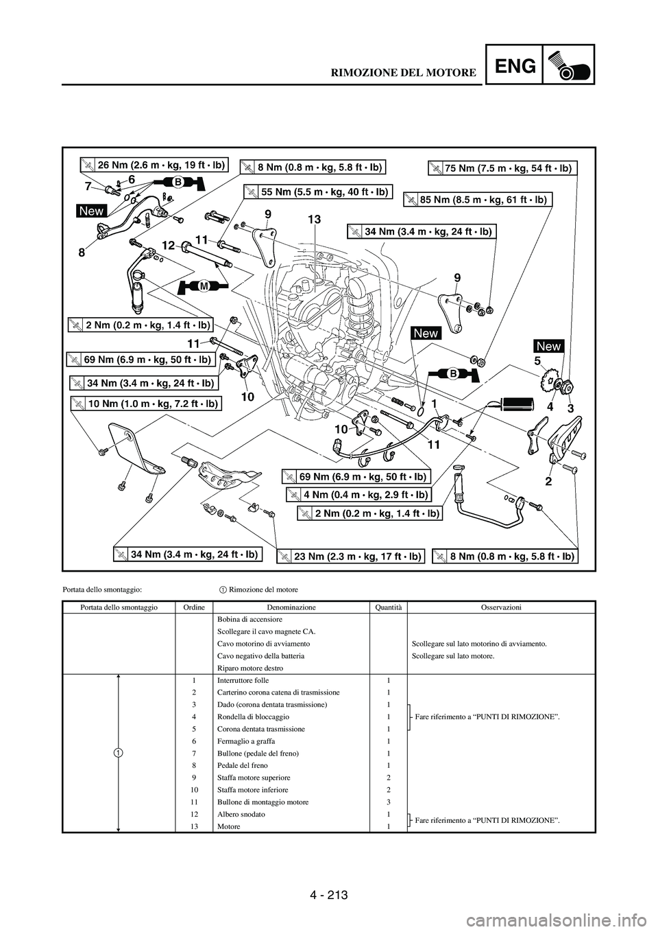
4 - 213
ENG
Portata dello smontaggio:1 Rimozione del motore
Portata dello smontaggio Ordine Denominazione QuantitàOsservazioni
Bobina di accensiore
Scollegare il cavo magnete CA.
Cavo motorino di avviamento Scollegare sul lato motorino di avviamento.
Cavo negativo della batteria Scollegare sul lato motore.
Riparo motore destro
1 Interruttore folle 1
2 Carterino corona catena di trasmissione 1
3 Dado (corona dentata trasmissione) 1
Fare riferimento a “PUNTI DI RIMOZIONE”. 4 Rondella di bloccaggio 1
5 Corona dentata trasmissione 1
6 Fermaglio a graffa 1
7 Bullone (pedale del freno) 1
8 Pedale del freno 1
9 Staffa motore superiore 2
10 Staffa motore inferiore 2
11 Bullone di montaggio motore 3
12 Albero snodato 1
Fare riferimento a “PUNTI DI RIMOZIONE”.
13 Motore 1
1
RIMOZIONE DEL MOTORE
Page 539 of 864
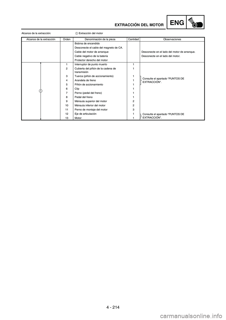
4 - 214
ENG
Alcance de la extracción:
1 Extracción del motor
Alcance de la extracción Orden Denominación de la pieza Cantidad Observaciones
Bobina de encendido
Desconecte el cable del magneto de CA.
Cable del motor de arranque Desconecte en el lado del motor de arranque.
Cable negativo de la batería Desconecte en el lado del motor.
Protector derecho del motor
1 Interruptor de punto muerto 1
2 Cubierta del piñón de la cadena de
transmisión1
3 Tuerca (piñón de accionamiento) 1
Consulte el apartado “PUNTOS DE
EXTRACCIÓN”. 4 Arandela de freno 1
5Piñón de accionamiento 1
6 Clip 1
7 Perno (pedal del freno) 1
8 Pedal del freno 1
9Ménsula superior del motor 2
10 Ménsula inferior del motor 2
11 Perno de montaje del motor 3
12 Eje de articulación1
Consulte el apartado “PUNTOS DE
EXTRACCIÓN”.
13 Motor 1
1
EXTRACCIÓN DEL MOTOR
Page 540 of 864
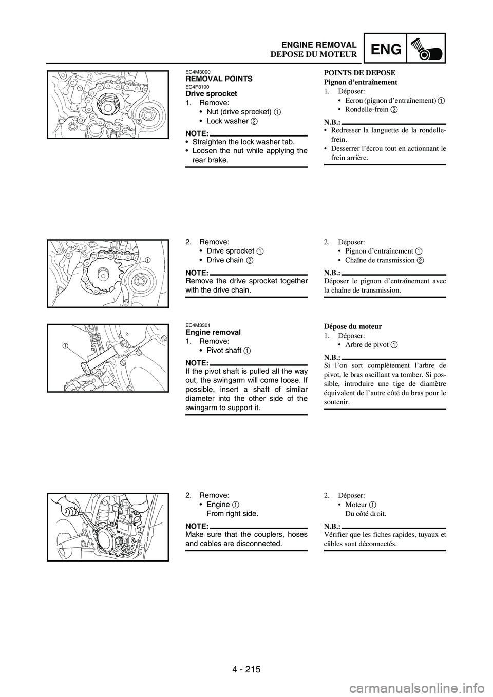
4 - 215
ENGENGINE REMOVAL
EC4M3000REMOVAL POINTSEC4F3100Drive sprocket
1. Remove:
Nut (drive sprocket)
1
Lock washer
2
NOTE:Straighten the lock washer tab.
Loosen the nut while applying the
rear brake.
2. Remove:
Drive sprocket
1
Drive chain
2
NOTE:Remove the drive sprocket together
with the drive chain.
EC4M3301Engine removal
1. Remove:
Pivot shaft
1
NOTE:If the pivot shaft is pulled all the way
out, the swingarm will come loose. If
possible, insert a shaft of similar
diameter into the other side of the
swingarm to support it.
2. Remove:
Engine
1
From right side.
NOTE:Make sure that the couplers, hoses
and cables are disconnected.
1
POINTS DE DEPOSE
Pignon d’entraînement
1. Déposer:
Ecrou (pignon d’entraînement) 1
Rondelle-frein 2
N.B.:
Redresser la languette de la rondelle-
frein.
Desserrer l’écrou tout en actionnant le
frein arrière.
2. Déposer:
Pignon d’entraînement 1
Chaîne de transmission 2
N.B.:
Déposer le pignon d’entraînement avec
la chaîne de transmission.
Dépose du moteur
1. Déposer:
Arbre de pivot 1
N.B.:
Si l’on sort complètement l’arbre de
pivot, le bras oscillant va tomber. Si pos-
sible, introduire une tige de diamètre
équivalent de l’autre côté du bras pour le
soutenir.
2. Déposer:
Moteur 1
Du côté droit.
N.B.:
Vérifier que les fiches rapides, tuyaux et
câbles sont déconnectés.
DEPOSE DU MOTEUR