Carburetor YAMAHA WR 250F 2006 Owners Manual
[x] Cancel search | Manufacturer: YAMAHA, Model Year: 2006, Model line: WR 250F, Model: YAMAHA WR 250F 2006Pages: 900, PDF Size: 23.77 MB
Page 22 of 900
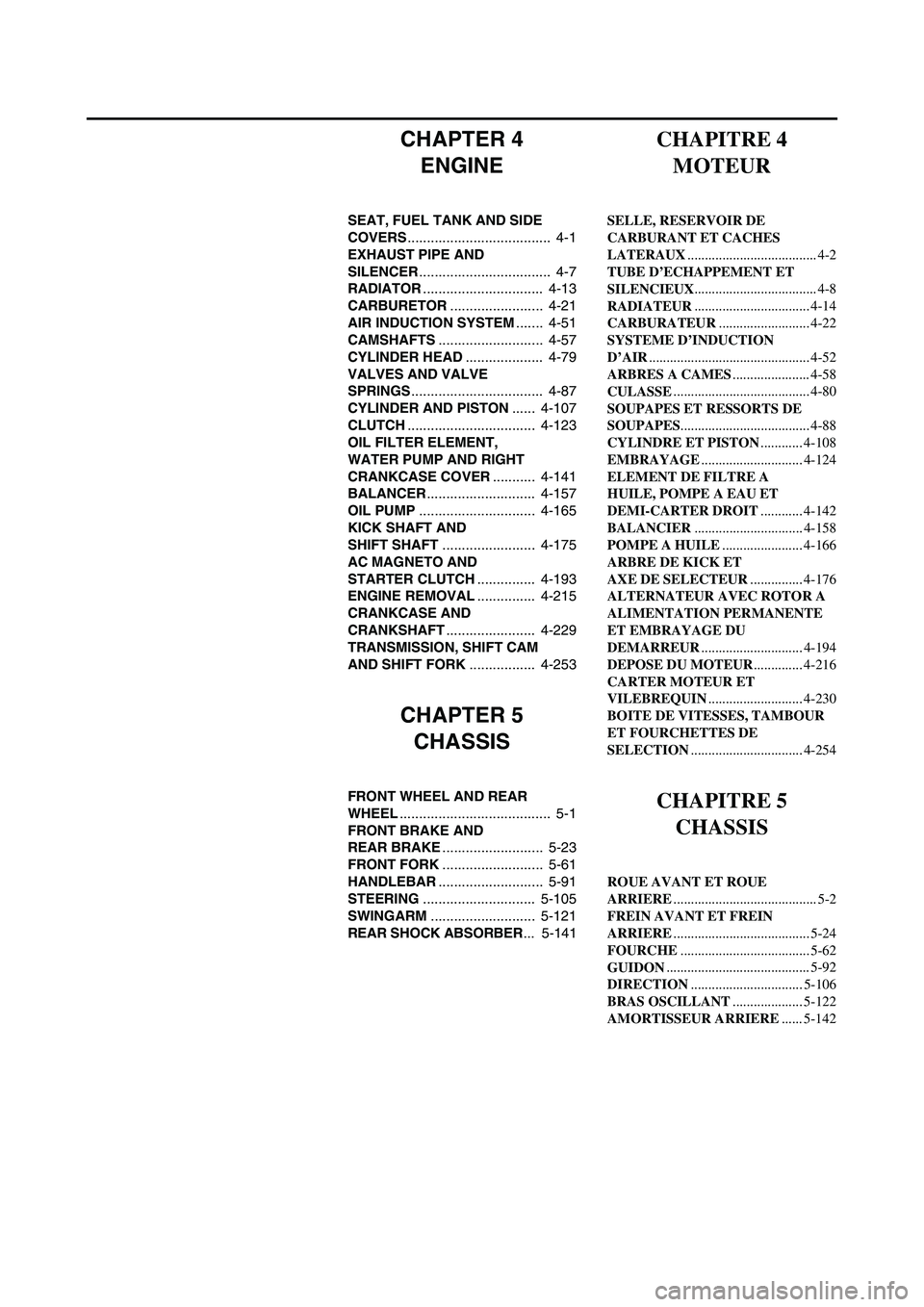
CHAPTER 4
ENGINE
SEAT, FUEL TANK AND SIDE
COVERS..................................... 4-1
EXHAUST PIPE AND
SILENCER.................................. 4-7
RADIATOR............................... 4-13
CARBURETOR........................ 4-21
AIR INDUCTION SYSTEM....... 4-51
CAMSHAFTS........................... 4-57
CYLINDER HEAD.................... 4-79
VALVES AND VALVE
SPRINGS.................................. 4-87
CYLINDER AND PISTON...... 4-107
CLUTCH................................. 4-123
OIL FILTER ELEMENT,
WATER PUMP AND RIGHT
CRANKCASE COVER........... 4-141
BALANCER............................ 4-157
OIL PUMP.............................. 4-165
KICK SHAFT AND
SHIFT SHAFT........................ 4-175
AC MAGNETO AND
STARTER CLUTCH............... 4-193
ENGINE REMOVAL............... 4-215
CRANKCASE AND
CRANKSHAFT....................... 4-229
TRANSMISSION, SHIFT CAM
AND SHIFT FORK................. 4-253
CHAPTER 5
CHASSIS
FRONT WHEEL AND REAR
WHEEL....................................... 5-1
FRONT BRAKE AND
REAR BRAKE.......................... 5-23
FRONT FORK.......................... 5-61
HANDLEBAR........................... 5-91
STEERING............................. 5-105
SWINGARM........................... 5-121
REAR SHOCK ABSORBER... 5-141
CHAPITRE 4
MOTEUR
SELLE, RESERVOIR DE
CARBURANT ET CACHES
LATERAUX..................................... 4-2
TUBE D’ECHAPPEMENT ET
SILENCIEUX................................... 4-8
RADIATEUR................................. 4-14
CARBURATEUR.......................... 4-22
SYSTEME D’INDUCTION
D’AIR.............................................. 4-52
ARBRES A CAMES...................... 4-58
CULASSE....................................... 4-80
SOUPAPES ET RESSORTS DE
SOUPAPES..................................... 4-88
CYLINDRE ET PISTON............ 4-108
EMBRAYAGE............................. 4-124
ELEMENT DE FILTRE A
HUILE, POMPE A EAU ET
DEMI-CARTER DROIT............ 4-142
BALANCIER............................... 4-158
POMPE A HUILE....................... 4-166
ARBRE DE KICK ET
AXE DE SELECTEUR............... 4-176
ALTERNATEUR AVEC ROTOR A
ALIMENTATION PERMANENTE
ET EMBRAYAGE DU
DEMARREUR............................. 4-194
DEPOSE DU MOTEUR.............. 4-216
CARTER MOTEUR ET
VILEBREQUIN........................... 4-230
BOITE DE VITESSES, TAMBOUR
ET FOURCHETTES DE
SELECTION................................ 4-254
CHAPITRE 5
CHASSIS
ROUE AVANT ET ROUE
ARRIERE......................................... 5-2
FREIN AVANT ET FREIN
ARRIERE....................................... 5-24
FOURCHE..................................... 5-62
GUIDON......................................... 5-92
DIRECTION................................ 5-106
BRAS OSCILLANT.................... 5-122
AMORTISSEUR ARRIERE...... 5-142
Page 56 of 900

1 - 31
GEN
INFO
FUEL COCK
The fuel cock supplies fuel from the
tank to carburetor and also filters the
fuel. The fuel cock has three posi-
tions:
OFF: With the lever in this position,
fuel will not flow. Always
return the lever to this posi-
tion when the engine is not
running.
ON: With the lever in this position
fuel flows to the carburetor.
Normal riding is done with the
lever in this position.
RES: With the lever in this position
fuel flows to the carburetor
from the reserve section of
the fuel tank after the main
supply of the fuel has been
depleted. Normal riding is
possible with the lever is in
this position, but it is recom-
mended to add fuel as soon
as possible.
COLD STARTER KNOB
When cold, the engine requires a
richer air-fuel mixture for starting. A
separate starter circuit, which is con-
trolled by the cold starter knob
1,
supplies this mixture. Pull the cold
starter knob out to open the circuit for
starting. When the engine has
warmed up, push it in to close the cir-
cuit.
HOT STARTER LEVER
The hot starter lever
1 is used when
starting a warm engine.
Use the hot starter lever when start-
ing the engine again immediately
after it was stopped (the engine is
still warm). Pulling the hot starter
lever injects secondary air to thin the
air-fuel mixture temporarily, allowing
the engine to be started more easily.
ROBINET DE CARBURANT
Le robinet de carburant amène le carbu-
rant du réservoir au carburateur tout en
le filtrant. Il a trois positions:
OFF: Lorsque le robinet est dans cette
position, l’arrivée de carburant
est coupée. Toujours replacer le
robinet dans cette position après
avoir coupé le moteur.
ON: Lorsque le robinet est dans cette
position, le carburant parvient au
carburateur. Pour rouler, le robi-
net doit se trouver dans cette
position.
RES: Lorsque le robinet est dans cette
position, le carburant provient de
la réserve du réservoir de carbu-
rant, après épuisement de l’ali-
mentation principale. Il est
possible de rouler normalement
avec le robinet dans cette posi-
tion, mais il est recommandé de
faire le plein le plus rapidement
possible.
COMMANDE DE DEPART A
FROID
Quand il est froid, le moteur a besoin
d’un mélange air - carburant plus riche
pour démarrer. Un circuit de démarrage
séparé, contrôlé par la commande de
départ à froid 1, fournit ce mélange.
Tirer la commande de départ à froid afin
d’ouvrir le circuit pour le démarrage.
Une fois le moteur chaud, la repousser
afin de refermer le circuit.
LEVIER DE DEMARRAGE A
CHAUD
Le levier de démarrage à chaud 1 s’uti-
lise pour démarrer un moteur chaud.
Ce levier s’utilise pour redémarrer le
moteur immédiatement après l’avoir
arrêté (le moteur est encore chaud).
Lorsqu’il est tiré, ce levier injecte une
quantité supplémentaire d’air dans le
mélange air-carburant, afin de le diluer
temporairement pour permettre un
démarrage plus aisé du moteur.
CONTROL FUNCTIONS
FONCTIONS DES COMMANDES
Page 76 of 900
1 - 51
GEN
INFO
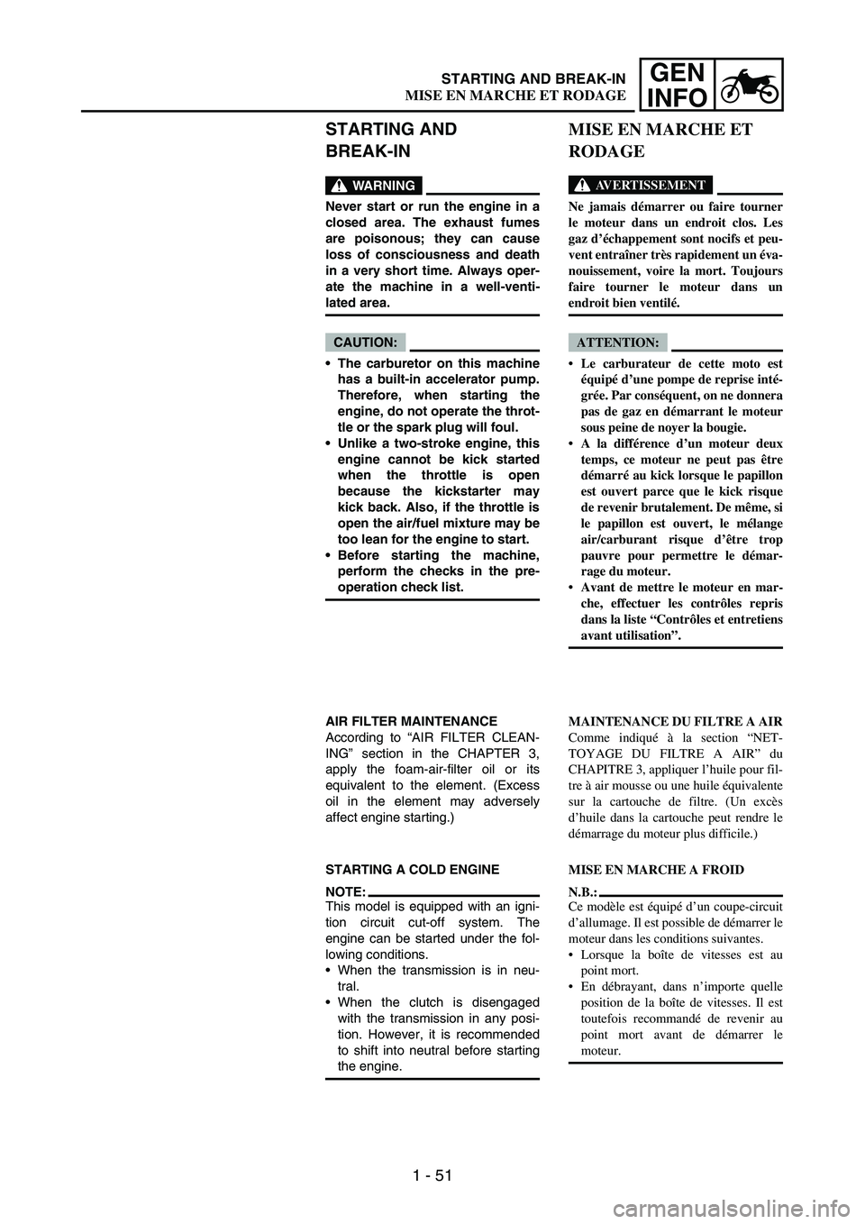
STARTING AND
BREAK-IN
WARNING
Never start or run the engine in a
closed area. The exhaust fumes
are poisonous; they can cause
loss of consciousness and death
in a very short time. Always oper-
ate the machine in a well-venti-
lated area.
CAUTION:
The carburetor on this machine
has a built-in accelerator pump.
Therefore, when starting the
engine, do not operate the throt-
tle or the spark plug will foul.
Unlike a two-stroke engine, this
engine cannot be kick started
when the throttle is open
because the kickstarter may
kick back. Also, if the throttle is
open the air/fuel mixture may be
too lean for the engine to start.
Before starting the machine,
perform the checks in the pre-
operation check list.
AIR FILTER MAINTENANCE
According to “AIR FILTER CLEAN-
ING” section in the CHAPTER 3,
apply the foam-air-filter oil or its
equivalent to the element. (Excess
oil in the element may adversely
affect engine starting.)
STARTING A COLD ENGINE
NOTE:This model is equipped with an igni-
tion circuit cut-off system. The
engine can be started under the fol-
lowing conditions.
When the transmission is in neu-
tral.
When the clutch is disengaged
with the transmission in any posi-
tion. However, it is recommended
to shift into neutral before starting
the engine.
MISE EN MARCHE ET
RODAGE
AVERTISSEMENT
Ne jamais démarrer ou faire tourner
le moteur dans un endroit clos. Les
gaz d’échappement sont nocifs et peu-
vent entraîner très rapidement un éva-
nouissement, voire la mort. Toujours
faire tourner le moteur dans un
endroit bien ventilé.
ATTENTION:
Le carburateur de cette moto est
équipé d’une pompe de reprise inté-
grée. Par conséquent, on ne donnera
pas de gaz en démarrant le moteur
sous peine de noyer la bougie.
A la différence d’un moteur deux
temps, ce moteur ne peut pas être
démarré au kick lorsque le papillon
est ouvert parce que le kick risque
de revenir brutalement. De même, si
le papillon est ouvert, le mélange
air/carburant risque d’être trop
pauvre pour permettre le démar-
rage du moteur.
Avant de mettre le moteur en mar-
che, effectuer les contrôles repris
dans la liste “Contrôles et entretiens
avant utilisation”.
MAINTENANCE DU FILTRE A AIR
Comme indiqué à la section “NET-
TOYAGE DU FILTRE A AIR” du
CHAPITRE 3, appliquer l’huile pour fil-
tre à air mousse ou une huile équivalente
sur la cartouche de filtre. (Un excès
d’huile dans la cartouche peut rendre le
démarrage du moteur plus difficile.)
MISE EN MARCHE A FROID
N.B.:
Ce modèle est équipé d’un coupe-circuit
d’allumage. Il est possible de démarrer le
moteur dans les conditions suivantes.
Lorsque la boîte de vitesses est au
point mort.
En débrayant, dans n’importe quelle
position de la boîte de vitesses. Il est
toutefois recommandé de revenir au
point mort avant de démarrer le
moteur.
STARTING AND BREAK-IN
MISE EN MARCHE ET RODAGE
Page 92 of 900
1 - 67
GEN
INFO
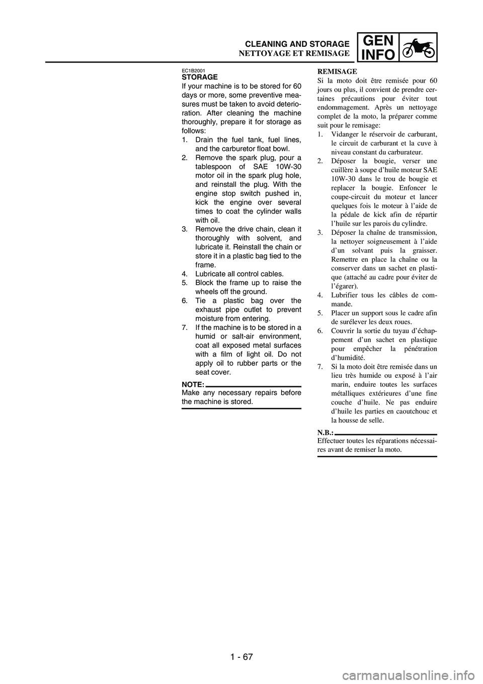
EC1B2001STORAGE
If your machine is to be stored for 60
days or more, some preventive mea-
sures must be taken to avoid deterio-
ration. After cleaning the machine
thoroughly, prepare it for storage as
follows:
1. Drain the fuel tank, fuel lines,
and the carburetor float bowl.
2. Remove the spark plug, pour a
tablespoon of SAE 10W-30
motor oil in the spark plug hole,
and reinstall the plug. With the
engine stop switch pushed in,
kick the engine over several
times to coat the cylinder walls
with oil.
3. Remove the drive chain, clean it
thoroughly with solvent, and
lubricate it. Reinstall the chain or
store it in a plastic bag tied to the
frame.
4. Lubricate all control cables.
5. Block the frame up to raise the
wheels off the ground.
6. Tie a plastic bag over the
exhaust pipe outlet to prevent
moisture from entering.
7. If the machine is to be stored in a
humid or salt-air environment,
coat all exposed metal surfaces
with a film of light oil. Do not
apply oil to rubber parts or the
seat cover.
NOTE:Make any necessary repairs before
the machine is stored.REMISAGE
Si la moto doit être remisée pour 60
jours ou plus, il convient de prendre cer-
taines précautions pour éviter tout
endommagement. Après un nettoyage
complet de la moto, la préparer comme
suit pour le remisage:
1. Vidanger le réservoir de carburant,
le circuit de carburant et la cuve à
niveau constant du carburateur.
2. Déposer la bougie, verser une
cuillère à soupe d’huile moteur SAE
10W-30 dans le trou de bougie et
replacer la bougie. Enfoncer le
coupe-circuit du moteur et lancer
quelques fois le moteur à l’aide de
la pédale de kick afin de répartir
l’huile sur les parois du cylindre.
3. Déposer la chaîne de transmission,
la nettoyer soigneusement à l’aide
d’un solvant puis la graisser.
Remettre en place la chaîne ou la
conserver dans un sachet en plasti-
que (attaché au cadre pour éviter de
l’égarer).
4. Lubrifier tous les câbles de com-
mande.
5. Placer un support sous le cadre afin
de surélever les deux roues.
6. Couvrir la sortie du tuyau d’échap-
pement d’un sachet en plastique
pour empêcher la pénétration
d’humidité.
7. Si la moto doit être remisée dans un
lieu très humide ou exposé à l’air
marin, enduire toutes les surfaces
métalliques extérieures d’une fine
couche d’huile. Ne pas enduire
d’huile les parties en caoutchouc et
la housse de selle.
N.B.:
Effectuer toutes les réparations nécessai-
res avant de remiser la moto.
CLEANING AND STORAGE
NETTOYAGE ET REMISAGE
Page 95 of 900
GENERAL SPECIFICATIONS
2 - 2
SPEC
Oil capacity:
Engine oil
Periodic oil change 1.2 L (1.06 Imp qt, 1.27 US qt)
With oil filter replacement 1.3 L (1.14 Imp qt, 1.37 US qt)
Total amount 1.4 L (1.23 Imp qt, 1.48 US qt)
Coolant capacity (including all routes): 1.26 L (1.11 Imp qt, 1.33 US qt)
Air filter: Wet type element
Fuel:
Type Premium unleaded gasoline only with a
research octane number of 95 or higher.
Tank capacity 8.0 L (1.76 Imp gal, 2.11 US gal)
Reserve 1.1 L (0.24 Imp gal, 0.29 US gal)
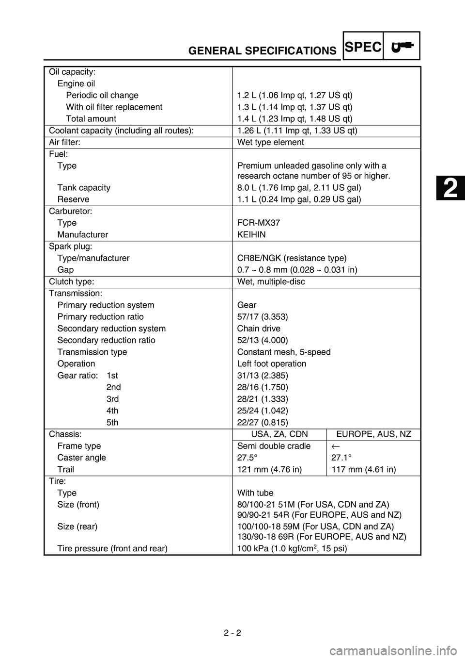
Carburetor:
Type FCR-MX37
Manufacturer KEIHIN
Spark plug:
Type/manufacturer CR8E/NGK (resistance type)
Gap 0.7 ~ 0.8 mm (0.028 ~ 0.031 in)
Clutch type: Wet, multiple-disc
Transmission:
Primary reduction system Gear
Primary reduction ratio 57/17 (3.353)
Secondary reduction system Chain drive
Secondary reduction ratio 52/13 (4.000)
Transmission type Constant mesh, 5-speed
Operation Left foot operation
Gear ratio: 1st 31/13 (2.385)
2nd 28/16 (1.750)
3rd 28/21 (1.333)
4th 25/24 (1.042)
5th 22/27 (0.815)
Chassis: USA, ZA, CDN EUROPE, AUS, NZ
Frame type Semi double cradle←
Caster angle 27.5°27.1°
Trail 121 mm (4.76 in) 117 mm (4.61 in)
Tire:
Type With tube
Size (front) 80/100-21 51M (For USA, CDN and ZA)
90/90-21 54R (For EUROPE, AUS and NZ)
Size (rear) 100/100-18 59M (For USA, CDN and ZA)
130/90-18 69R (For EUROPE, AUS and NZ)
Tire pressure (front and rear) 100 kPa (1.0 kgf/cm
2, 15 psi)
1
2
3
4
5
6
7
Page 101 of 900

MAINTENANCE SPECIFICATIONS
2 - 8
SPEC
Clutch:
Friction plate thickness 2.9 ~ 3.1 mm (0.114 ~ 0.122 in) 2.7 mm
(0.106 in)
Quantity 9 ----
Clutch plate thickness 1.1 ~ 1.3 mm (0.043 ~ 0.051 in) ----
Quantity 8 ----
Warp limit ---- 0.1 mm
(0.004 in)
Clutch spring free length 37.0 mm (1.46 in) 36.0 mm
(1.42 in)
Quantity 5 ----
Clutch housing thrust clearance 0.10 ~ 0.35 mm
(0.0039 ~ 0.0138 in)----
Clutch housing radial clearance 0.010 ~ 0.044 mm
(0.0004 ~ 0.0017 in)----
Clutch release method Inner push, cam push ----
Shifter:
Shifter type Cam drum and guide bar ----
Guide bar bending limit ---- 0.05 mm
(0.002 in)
Kickstarter:
Type Kick and ratchet type ----
Carburetor:
Type/manufacturer FCR-MX37/KEIHIN
I. D. mark 5UMB B0
Main jet (M.J) #168
Main air jet (M.A.J) #115
Jet needle (J.N) NGSU
Cutaway (C.A) 1.5
Pilot jet (P.J) #42
Pilot air jet (P.A.J) #70
Pilot outlet (P.O)ø0.9
Bypass (B.P)ø1.0
Valve seat size (V.S)ø3.8
Starter jet (G.S) #68
Leak jet (Acc.P) #70
Float height (F.H) 8 mm (0.31 in)
Engine idle speed 1,750 ~ 1,950 r/min
Intake vacuum 31.3 ~ 36.7 kPa
(235 ~ 275 mmHg,
9.25 ~ 10.83 inHg)
Hot starter lever free play 3 ~ 6 mm
(0.12 ~ 0.24 in) Item Standard Limit
Page 103 of 900

MAINTENANCE SPECIFICATIONS
2 - 10
SPEC
Part to be tightened Thread size Q’tyTightening torque
Nm m·kg ft·lb
Spark plug M10S × 1.0 1 13 1.3 9.4
Camshaft cap M6 × 1.0 10 10 1.0 7.2
Cylinder head blind plug screw M12 × 1.0 1 28 2.8 20
Cylinder head (stud bolt) M6 × 1.0 2 7 0.7 5.1
(stud bolt) M8 × 1.25 1 15 1.5 11
(bolt) M9 × 1.25 4 38 3.8 27
(nut) M6 × 1.0 2 10 1.0 7.2
Cylinder head cover M6 × 1.0 2 10 1.0 7.2
Cylinder M6 × 1.0 1 10 1.0 7.2
Balancer weight M6 × 1.0 2 10 1.0 7.2
Balancer shaft driven gear M14 × 1.0 1 50 5.0 36
Timing chain guide (intake side) M6 × 1.0 2 10 1.0 7.2
Timing chain tensioner M6 × 1.0 2 10 1.0 7.2
Timing chain tensioner cap bolt M6 × 1.0 1 7 0.7 5.1
Impeller M8 × 1.25 1 14 1.4 10
Radiator hose clamp M6 × 1.0 8 2 0.2 1.4
Coolant drain bolt M6 × 1.0 1 10 1.0 7.2
Water pump housing M6 × 1.0 4 10 1.0 7.2
Radiator M6 × 1.0 6 10 1.0 7.2
Radiator guard M6 × 1.0 2 10 1.0 7.2
Radiator pipe M6 × 1.0 1 10 1.0 7.2
Oil pump cover M4 × 0.7 1 2 0.2 1.4
Oil pump M6 × 1.0 3 10 1.0 7.2
Oil filter element drain bolt M6 × 1.0 1 10 1.0 7.2
Oil filter element cover M6 × 1.0 2 10 1.0 7.2
Oil strainer M6 × 1.0 2 10 1.0 7.2
Oil delivery pipe 1 (M10) M10 × 1.25 1 20 2.0 14
(M8) M8 × 1.25 2 18 1.8 13
Oil hose M6 × 1.0 2 8 0.8 5.8
Oil hose clamp—220.21.4
Oil strainer and frame M14 × 1.5 1 70 7.0 50
Carburetor joint clamp M4 × 0.7 2 3 0.3 2.2
Air filter joint clamp M6 × 1.0 1 3 0.3 2.2
Throttle cable (pull) M6 × 1.0 1 4 0.4 2.9
Throttle cable (return) M12 × 1.0 1 11 1.1 8.0
Throttle cable cover M5 × 0.8 2 4 0.4 2.9
Hot starter plunger M12 × 1.0 1 2 0.2 1.4
Air filter case M6 × 1.0 2 8 0.8 5.8
Air filter joint and air filter case M5 × 0.8 1 4 0.4 2.9
Exhaust pipe (nut) M8 × 1.25 1 13 1.3 9.4
(bolt) M8 × 1.25 1 24 2.4 17
Exhaust pipe protector M6 × 1.0 3 10 1.0 7.2
Page 190 of 900
SPEC
2 - 97
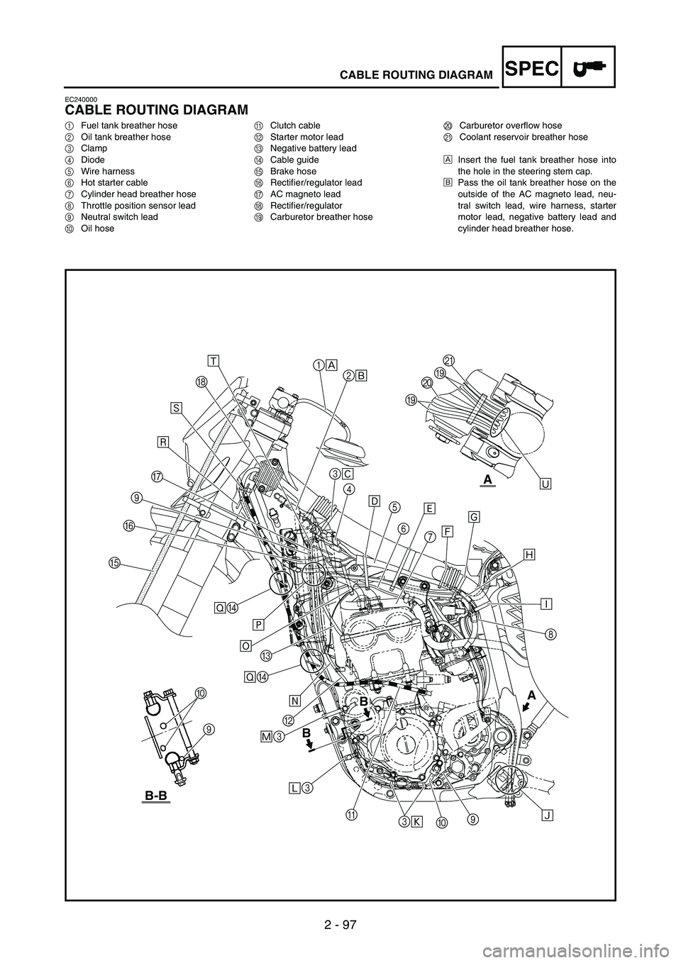
CABLE ROUTING DIAGRAM
EC240000
CABLE ROUTING DIAGRAM
1Fuel tank breather hose
2Oil tank breather hose
3Clamp
4Diode
5Wire harness
6Hot starter cable
7Cylinder head breather hose
8Throttle position sensor lead
9Neutral switch lead
0Oil hoseAClutch cable
BStarter motor lead
CNegative battery lead
DCable guide
EBrake hose
FRectifier/regulator lead
GAC magneto lead
HRectifier/regulator
ICarburetor breather hoseJCarburetor overflow hose
KCoolant reservoir breather hose
ÈInsert the fuel tank breather hose into
the hole in the steering stem cap.
ÉPass the oil tank breather hose on the
outside of the AC magneto lead, neu-
tral switch lead, wire harness, starter
motor lead, negative battery lead and
cylinder head breather hose.
B
B
B-B
A
Ô3B
Ó3 Ö
C
× EF
9
GÙ
H
Ú
Û
1
È
3
Ê
4
Ë
5
6
7 Ì
ÍÎ
Ï
Ñ Ð
8
0 3
ÒÜ II
JK
9 A 2
É
0
9A
ØD ØD
Õ
Page 192 of 900

SPEC
2 - 99
CABLE ROUTING DIAGRAM
ÊFasten the diode (at the white tape), rectifier/regulator lead,
CDI unit lead (at the protecting tube) and AC magneto coupler
(connected to the CDI unit).
ËFasten the wire harness, coolant reservoir hose, hot starter
cable, negative battery lead and starter motor lead.
ÌFasten the wire harness, negative battery lead, starter motor
lead and coolant reservoir hose at the white tape for the nega-
tive battery lead.
ÍFasten the wire harness at its white tape.
ÎFasten the wire harness, starter motor lead and negative bat-
tery lead.
ÏMake sure that the throttle position sensor coupler does not go
outside the chassis.ÐFasten the throttle position sensor lead.
ÑPass the carburetor breather hoses, carburetor overflow hose
and coolant reservoir breather hose between the connecting
rod and cross tube (frame).
ÒFasten the neutral switch lead and oil hose together with the
plastic locking ties and cut off the tie ends.
ÓFasten the neutral switch lead.
ÔFasten the neutral Aswitch lead and AC magneto lead.
ÕPass the starter motor lead in front of the radiator hose 4.
ÖFasten the wire harness, starter motor lead and negative bat-
tery lead so that the plastic locking tie ends do not contact the
ignition coil lead.
B
B
B-B
A
Ô3B
Ó3 Ö
C
× EF
9
GÙ
H
Ú
Û
1
È
3
Ê
4
Ë
5
6
7 Ì
ÍÎ
Ï
Ñ Ð
8
0 3
ÒÜ II
JK
9 A 2
É
0
9A
ØD ØD
Õ
Page 194 of 900

SPEC
2 - 101
CABLE ROUTING DIAGRAM
×Pass the wire harness on the outside of the neutral switch lead
and AC magneto lead.
ØPass the clutch cable through the cable guides.
ÙPass the wire harness and clutch cable through the cable
guide.
ÚFasten the rectifier/regulator lead to the cable guide.
ÛFasten the AC magneto lead and neutral switch lead to the
cable guide at their protecting tube.
ÜPass the carburetor breather hoses, carburetor overflow hose
and coolant reservoir breather hose so that the hoses do not
contact the rear shock absorber.
B
B
B-B
A
Ô3B
Ó3 Ö
C
× EF
9
GÙ
H
Ú
Û
1
È
3
Ê
4
Ë
5
6
7 Ì
ÍÎ
Ï
Ñ Ð
8
0 3
ÒÜ II
JK
9 A 2
É
0
9A
ØD ØD
Õ