radiator YAMAHA WR 250F 2006 Owners Manual
[x] Cancel search | Manufacturer: YAMAHA, Model Year: 2006, Model line: WR 250F, Model: YAMAHA WR 250F 2006Pages: 900, PDF Size: 23.77 MB
Page 22 of 900
CHAPTER 4
ENGINE
SEAT, FUEL TANK AND SIDE
COVERS..................................... 4-1
EXHAUST PIPE AND
SILENCER.................................. 4-7
RADIATOR............................... 4-13
CARBURETOR........................ 4-21
AIR INDUCTION SYSTEM....... 4-51
CAMSHAFTS........................... 4-57
CYLINDER HEAD.................... 4-79
VALVES AND VALVE
SPRINGS.................................. 4-87
CYLINDER AND PISTON...... 4-107
CLUTCH................................. 4-123
OIL FILTER ELEMENT,
WATER PUMP AND RIGHT
CRANKCASE COVER........... 4-141
BALANCER............................ 4-157
OIL PUMP.............................. 4-165
KICK SHAFT AND
SHIFT SHAFT........................ 4-175
AC MAGNETO AND
STARTER CLUTCH............... 4-193
ENGINE REMOVAL............... 4-215
CRANKCASE AND
CRANKSHAFT....................... 4-229
TRANSMISSION, SHIFT CAM
AND SHIFT FORK................. 4-253
CHAPTER 5
CHASSIS
FRONT WHEEL AND REAR
WHEEL....................................... 5-1
FRONT BRAKE AND
REAR BRAKE.......................... 5-23
FRONT FORK.......................... 5-61
HANDLEBAR........................... 5-91
STEERING............................. 5-105
SWINGARM........................... 5-121
REAR SHOCK ABSORBER... 5-141
CHAPITRE 4
MOTEUR
SELLE, RESERVOIR DE
CARBURANT ET CACHES
LATERAUX..................................... 4-2
TUBE D’ECHAPPEMENT ET
SILENCIEUX................................... 4-8
RADIATEUR................................. 4-14
CARBURATEUR.......................... 4-22
SYSTEME D’INDUCTION
D’AIR.............................................. 4-52
ARBRES A CAMES...................... 4-58
CULASSE....................................... 4-80
SOUPAPES ET RESSORTS DE
SOUPAPES..................................... 4-88
CYLINDRE ET PISTON............ 4-108
EMBRAYAGE............................. 4-124
ELEMENT DE FILTRE A
HUILE, POMPE A EAU ET
DEMI-CARTER DROIT............ 4-142
BALANCIER............................... 4-158
POMPE A HUILE....................... 4-166
ARBRE DE KICK ET
AXE DE SELECTEUR............... 4-176
ALTERNATEUR AVEC ROTOR A
ALIMENTATION PERMANENTE
ET EMBRAYAGE DU
DEMARREUR............................. 4-194
DEPOSE DU MOTEUR.............. 4-216
CARTER MOTEUR ET
VILEBREQUIN........................... 4-230
BOITE DE VITESSES, TAMBOUR
ET FOURCHETTES DE
SELECTION................................ 4-254
CHAPITRE 5
CHASSIS
ROUE AVANT ET ROUE
ARRIERE......................................... 5-2
FREIN AVANT ET FREIN
ARRIERE....................................... 5-24
FOURCHE..................................... 5-62
GUIDON......................................... 5-92
DIRECTION................................ 5-106
BRAS OSCILLANT.................... 5-122
AMORTISSEUR ARRIERE...... 5-142
Page 23 of 900
KAPITEL 4
MOTOR
SITZBANK, KRAFTSTOFFTANK
UND SEITENABDECKUNGEN... 4-2
AUSPUFFKRÜMMER UND
SCHALLDÄMPFER.................... 4-8
KÜHLER.................................... 4-14
VERGASER............................... 4-22
SEKUNDÄRLUFTSYSTEM...... 4-52
NOCKENWELLEN.................... 4-58
ZYLINDERKOPF....................... 4-80
VENTILE UND
VENTILFEDERN....................... 4-88
ZYLINDER UND KOLBEN...... 4-108
KUPPLUNG............................. 4-124
ÖLFILTER, WASSERPUMPE UND
KURBELGEHÄUSEDECKEL
RECHTS.................................. 4-142
AUSGLEICHSWELLE............. 4-158
ÖLPUMPE............................... 4-166
KICKHEBELWELLE UND
SCHALTWELLE...................... 4-176
LICHTMASCHINE UND
STARTERKUPPLUNG............ 4-194
MOTOR DEMONTIEREN........ 4-216
KURBELGEHÄUSE UND
KURBELWELLE..................... 4-230
GETRIEBE, SCHALTWALZE
UND SCHALTGABELN.......... 4-254
KAPITEL 5
FAHRWERK
VORDER- UND HINTERRAD..... 5-2
VORDER- UND
HINTERRADBREMSEN............ 5-24
TELESKOPGABEL................... 5-62
LENKER.................................... 5-92
LENKUNG............................... 5-106
SCHWINGE............................. 5-122
FEDERBEIN............................ 5-142
CAPITOLO 4
MOTORE
SELLA, SERBATOIO
CARBURANTE E FIANCHETTI....4-3
TUBO DI SCARICO E
SILENZIATORE............................ 4-9
RADIATORE................................ 4-15
CARBURATORE.......................... 4-23
SISTEMA DI INIEZIONE
ARIA............................................... 4-53
ALBERI A CAMME..................... 4-59
TESTATA...................................... 4-81
VALVOLE E MOLLE
VALVOLE..................................... 4-89
CILINDRO E PISTONE............ 4-109
FRIZIONE................................... 4-125
ELEMENTO FILTRO OLIO,
POMPA DELL’ACQUA E
COPERCHIO
CARTER DESTRO.................... 4-143
EQUILIBRATORE..................... 4-159
POMPA DELL’OLIO................ 4-167
ALBERO PEDALE E ALBERO
DEL CAMBIO............................. 4-177
MAGNETE AC E GIUNTO
STARTER.................................... 4-195
RIMOZIONE DEL MOTORE.... 4-217
CARTER E ALBERO
MOTORE..................................... 4-231
TRASMISSIONE, CAMMA
DEL CAMBIO E FORCELLA
DEL CAMBIO............................. 4-255
CAPITOLO 5
PARTE CICLISTICA
RUOTA ANTERIORE E
POSTERIORE................................. 5-3
FRENO ANTERIORE E
POSTERIORE............................... 5-25
FORCELLA ANTERIORE......... 5-63
MANUBRIO.................................. 5-93
STERZO....................................... 5-107
FORCELLONE
OSCILLANTE............................. 5-123
AMMORTIZZATORE
POSTERIORE............................. 5-143
CAPÍTULO 4
MOTOR
SILLÍN, DEPÓSITO DE
COMBUSTIBLE Y CUBIERTAS
LATERALES............................... 4-4
TUBO DE ESCAPE Y
SILENCIADOR.......................... 4-10
RADIADOR................................ 4-16
CARBURADOR......................... 4-24
SISTEMA DE INDUCCIÓN
DE AIRE.................................... 4-54
EJES DE LEVAS....................... 4-60
CULATA.................................... 4-82
VÁLVULAS Y MUELLES DE
VÁLVULAS................................ 4-90
CILINDRO Y PISTÓN.............. 4-110
EMBRAGUE............................ 4-126
ELEMENTO DEL FILTRO DE
ACEITE, BOMBA DE AGUA Y
TAPA DEL CÁRTER
DERECHA............................... 4-144
COMPENSADOR.................... 4-160
BOMBA DE ACEITE............... 4-168
EJE DEL PEDAL DE ARRANQUE
Y EJE DEL CAMBIO............... 4-178
MAGNETO CA Y EMBRAGUE
DE ARRANQUE...................... 4-196
DESMONTAJE DEL
MOTOR.................................... 4-218
CÁRTER Y CIGÜEÑAL........... 4-232
CAJA DE CAMBIOS,
LEVA DE CAMBIO Y
HORQUILLA DE CAMBIO...... 4-256
CAPÍTULO 5
CHASIS
RUEDA DELANTERA Y
RUEDA TRASERA...................... 5-4
FRENO DELANTERO Y
FRENO TRASERO.................... 5-26
HORQUILLA DELANTERA...... 5-64
MANILLAR................................ 5-94
DIRECCIÓN............................. 5-108
BASCULANTE........................ 5-124
AMORTIGUADOR
TRASERO............................... 5-144
Page 26 of 900
1 - 1
GEN
INFODESCRIPTION
EC100000
GENERAL INFORMATION
EC110000
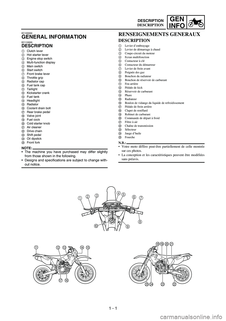
DESCRIPTION
1Clutch lever
2Hot starter lever
3Engine stop switch
4Multi-function display
5Main switch
6Start switch
7Front brake lever
8Throttle grip
9Radiator cap
0Fuel tank cap
ATaillight
BKickstarter crank
CFuel tank
DHeadlight
ERadiator
FCoolant drain bolt
GRear brake pedal
HValve joint
IFuel cock
JCold starter knob
KAir cleaner
LDrive chain
MShift pedal
NOil dipstick
OFront fork
NOTE:The machine you have purchased may differ slightly
from those shown in the following.
Designs and specifications are subject to change with-
out notice.
A
BCD
E
F G
1234
5
6
7
8
9 0
HI
J
K
L M
N O
RENSEIGNEMENTS GENERAUX
DESCRIPTION
1Levier d’embrayage
2Levier de démarrage à chaud
3Coupe-circuit du moteur
4Ecran multifonction
5Contacteur à clé
6Contacteur du démarreur
7Levier de frein avant
8Poignée des gaz
9Bouchon du radiateur
0Bouchon de réservoir de carburant
AFeu arrière
BPédale de kick
CRéservoir de carburant
DPhare
ERadiateur
FBoulon de vidange du liquide de refroidissement
GPédale de frein arrière
HClapet de reniflard
IRobinet de carburant
JCommande de départ à froid
KFiltre à air
LChaîne de transmission
MSélecteur
NJauge d’huile
OFourche
N.B.:
Votre moto diffère peut-être partiellement de celle montrée
sur ces photos.
La conception et les caractéristiques peuvent être modifiées
sans préavis.
DESCRIPTION
Page 27 of 900
1 - 2
GEN
INFO
ALLGEMEINE
ANGABEN
FAHRZEUGBESCHREI-
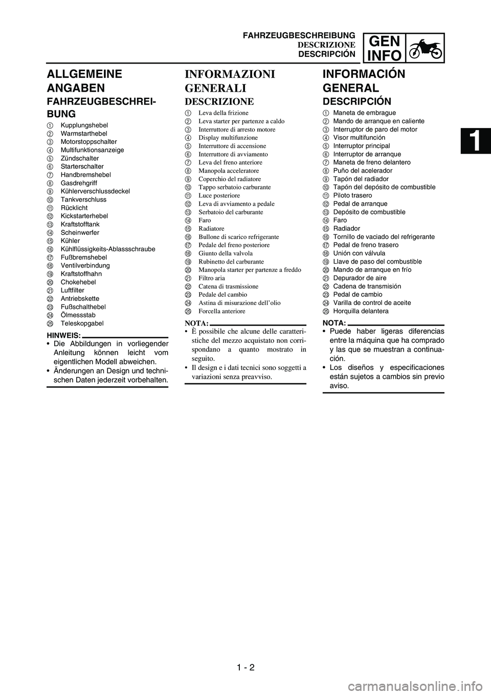
BUNG
1Kupplungshebel
2Warmstarthebel
3Motorstoppschalter
4Multifunktionsanzeige
5Zündschalter
6Starterschalter
7Handbremshebel
8Gasdrehgriff
9Kühlerverschlussdeckel
0Tankverschluss
ARücklicht
BKickstarterhebel
CKraftstofftank
DScheinwerfer
EKühler
FKühlflüssigkeits-Ablassschraube
GFußbremshebel
HVentilverbindung
IKraftstoffhahn
JChokehebel
KLuftfilter
LAntriebskette
MFußschalthebel
NÖlmessstab
OTeleskopgabel
HINWEIS:
Die Abbildungen in vorliegender
Anleitung können leicht vom
eigentlichen Modell abweichen.
Änderungen an Design und techni-
schen Daten jederzeit vorbehalten.
INFORMAZIONI
GENERALI
DESCRIZIONE
1Leva della frizione
2Leva starter per partenze a caldo
3Interruttore di arresto motore
4Display multifunzione
5Interruttore di accensione
6Interruttore di avviamento
7Leva del freno anteriore
8Manopola acceleratore
9Coperchio del radiatore
0Tappo serbatoio carburante
ALuce posteriore
BLeva di avviamento a pedale
CSerbatoio del carburante
DFaro
ERadiatore
FBullone di scarico refrigerante
GPedale del freno posteriore
HGiunto della valvola
IRubinetto del carburante
JManopola starter per partenze a freddo
KFiltro aria
LCatena di trasmissione
MPedale del cambio
NAstina di misurazione dell’olio
OForcella anteriore
NOTA:
È possibile che alcune delle caratteri-
stiche del mezzo acquistato non corri-
spondano a quanto mostrato in
seguito.
Il design e i dati tecnici sono soggetti a
variazioni senza preavviso.
INFORMACIÓN
GENERAL
DESCRIPCIÓN
1Maneta de embrague
2Mando de arranque en caliente
3Interruptor de paro del motor
4Visor multifunción
5Interruptor principal
6Interruptor de arranque
7Maneta de freno delantero
8Puño del acelerador
9Tapón del radiador
0Tapón del depósito de combustible
APiloto trasero
BPedal de arranque
CDepósito de combustible
DFaro
ERadiador
FTornillo de vaciado del refrigerante
GPedal de freno trasero
HUnión con válvula
ILlave de paso del combustible
JMando de arranque en frío
KDepurador de aire
LCadena de transmisión
MPedal de cambio
NVarilla de control de aceite
OHorquilla delantera
NOTA:
Puede haber ligeras diferencias
entre la máquina que ha comprado
y las que se muestran a continua-
ción.
Los diseños y especificaciones
están sujetos a cambios sin previo
aviso.
FAHRZEUGBESCHREIBUNG
DESCRIZIONE
DESCRIPCIÓN
1
2
3
4
5
6
7
Page 36 of 900
1 - 11
GEN
INFO
SPECIAL TOOLS
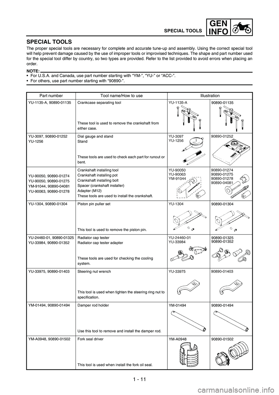
SPECIAL TOOLS
The proper special tools are necessary for complete and accurate tune-up and assembly. Using the correct special tool
will help prevent damage caused by the use of improper tools or improvised techniques. The shape and part number used
for the special tool differ by country, so two types are provided. Refer to the list provided to avoid errors when placing an
order.
NOTE:For U.S.A. and Canada, use part number starting with “YM-”, “YU-” or “ACC-”.
For others, use part number starting with “90890-”.
Part number Tool name/How to use Illustration
YU-1135-A, 90890-01135 Crankcase separating tool
These tool is used to remove the crankshaft from
either case.
YU-3097, 90890-01252
YU-1256Dial gauge and stand
Stand
These tools are used to check each part for runout or
bent.
YU-90050, 90890-01274
YU-90050, 90890-01275
YM-91044, 90890-04081
YU-90063, 90890-01278Crankshaft installing tool
Crankshaft installing pot
Crankshaft installing bolt
Spacer (crankshaft installer)
Adapter (M12)
These tools are used to install the crankshaft.
YU-1304, 90890-01304 Piston pin puller set
This tool is used to remove the piston pin.
YU-24460-01, 90890-01325
YU-33984, 90890-01352Radiator cap tester
Radiator cap tester adapter
These tools are used for checking the cooling
system.
YU-33975, 90890-01403 Steering nut wrench
This tool is used when tighten the steering ring nut to
specification.
YM-01494, 90890-01494 Damper rod holder
Use this tool to remove and install the damper rod.
YM-A0948, 90890-01502 Fork seal driver
This tool is used when install the fork oil seal.90890-01135
90890-01304
90890-01325
90890-01352
YM-0149490890-01494
YM-A094890890-01502
Page 45 of 900
1 - 20
GEN
INFO
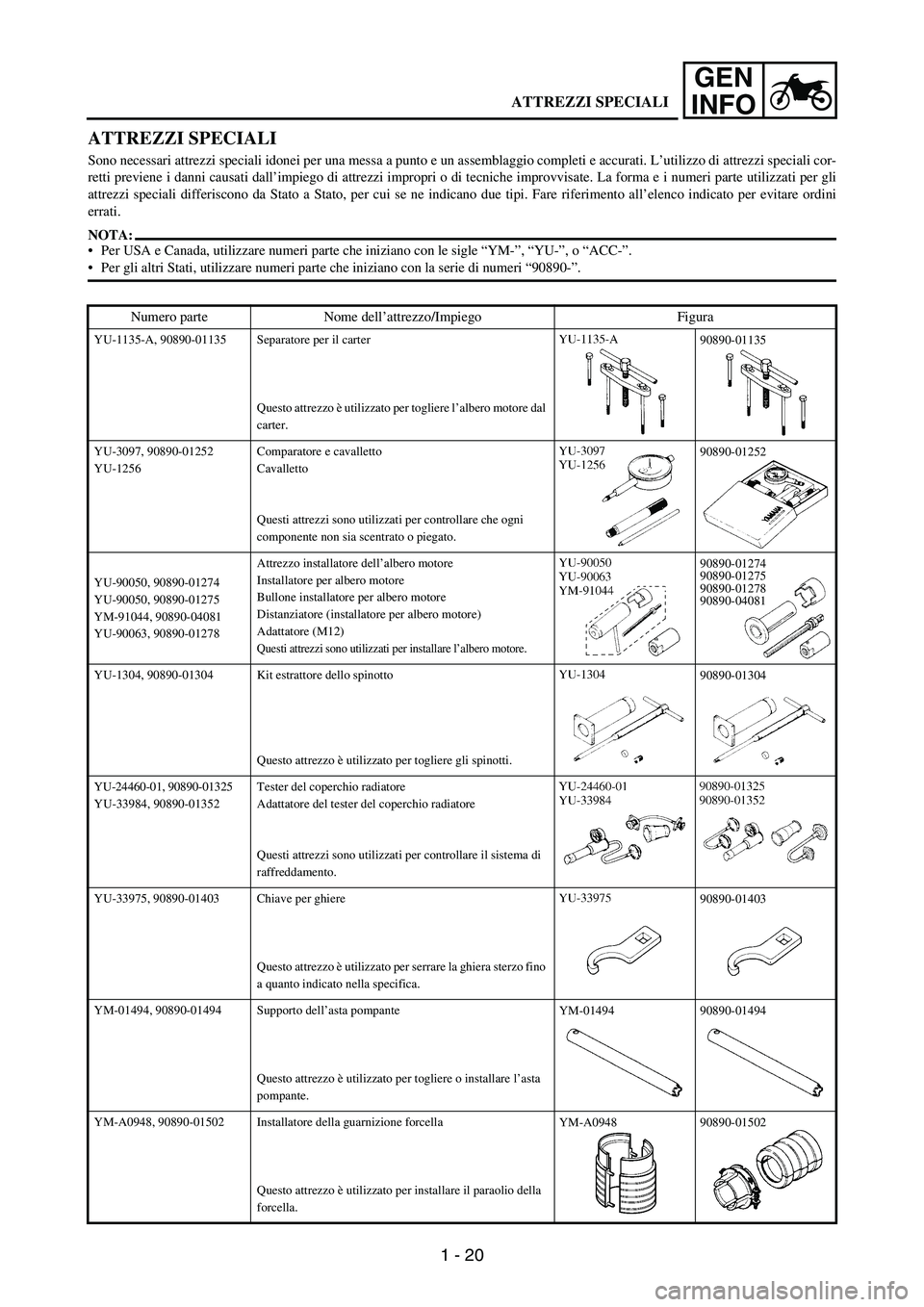
ATTREZZI SPECIALI
Sono necessari attrezzi speciali idonei per una messa a punto e un assemblaggio completi e accurati. L’utilizzo di attrezzi speciali cor-
retti previene i danni causati dall’impiego di attrezzi impropri o di tecniche improvvisate. La forma e i numeri parte utilizzati per gli
attrezzi speciali differiscono da Stato a Stato, per cui se ne indicano due tipi. Fare riferimento all’elenco indicato per evitare ordini
errati.
NOTA:
Per USA e Canada, utilizzare numeri parte che iniziano con le sigle “YM-”, “YU-”, o “ACC-”.
Per gli altri Stati, utilizzare numeri parte che iniziano con la serie di numeri “90890-”.
Numero parte Nome dell’attrezzo/Impiego Figura
YU-1135-A, 90890-01135 Separatore per il carter
Questo attrezzo è utilizzato per togliere l’albero motore dal
carter.
YU-3097, 90890-01252
YU-1256Comparatore e cavalletto
Cavalletto
Questi attrezzi sono utilizzati per controllare che ogni
componente non sia scentrato o piegato.
YU-90050, 90890-01274
YU-90050, 90890-01275
YM-91044, 90890-04081
YU-90063, 90890-01278Attrezzo installatore dell’albero motore
Installatore per albero motore
Bullone installatore per albero motore
Distanziatore (installatore per albero motore)
Adattatore (M12)
Questi attrezzi sono utilizzati per installare l’albero motore.
YU-1304, 90890-01304 Kit estrattore dello spinotto
Questo attrezzo è utilizzato per togliere gli spinotti.
YU-24460-01, 90890-01325
YU-33984, 90890-01352Tester del coperchio radiatore
Adattatore del tester del coperchio radiatore
Questi attrezzi sono utilizzati per controllare il sistema di
raffreddamento.
YU-33975, 90890-01403 Chiave per ghiere
Questo attrezzo è utilizzato per serrare la ghiera sterzo fino
a quanto indicato nella specifica.
YM-01494, 90890-01494 Supporto dell’asta pompante
Questo attrezzo è utilizzato per togliere o installare l’asta
pompante.
YM-A0948, 90890-01502 Installatore della guarnizione forcella
Questo attrezzo è utilizzato per installare il paraolio della
forcella.
90890-01135
90890-01252
90890-01274
90890-01275
90890-01278
90890-04081
90890-01304
90890-01403
YM-0149490890-01494
YM-A094890890-01502
ATTREZZI SPECIALI
Page 102 of 900
MAINTENANCE SPECIFICATIONS
2 - 9
SPEC
Lubrication system:
Oil filter type Paper type ----
Oil pump type Trochoid type ----
Tip clearance 0.12 mm or less
(0.0047 in or less)0.20 mm
(0.008 in)
Side clearance 0.09 ~ 0.17 mm
(0.0035 ~ 0.0067 in)0.24 mm
(0.009 in)
Housing and rotor clearance 0.03 ~ 0.10 mm
(0.0012 ~ 0.0039 in)0.17 mm
(0.0067 in)
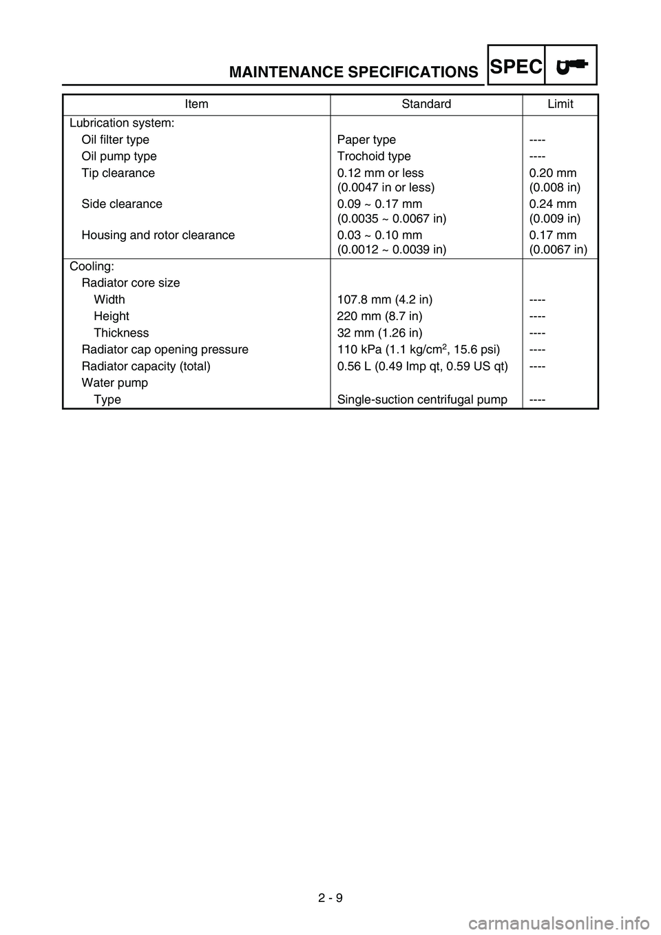
Cooling:
Radiator core size
Width 107.8 mm (4.2 in) ----
Height 220 mm (8.7 in) ----
Thickness 32 mm (1.26 in) ----
Radiator cap opening pressure 110 kPa (1.1 kg/cm
2, 15.6 psi) ----
Radiator capacity (total) 0.56 L (0.49 Imp qt, 0.59 US qt) ----
Water pump
Type Single-suction centrifugal pump ----Item Standard Limit
Page 103 of 900

MAINTENANCE SPECIFICATIONS
2 - 10
SPEC
Part to be tightened Thread size Q’tyTightening torque
Nm m·kg ft·lb
Spark plug M10S × 1.0 1 13 1.3 9.4
Camshaft cap M6 × 1.0 10 10 1.0 7.2
Cylinder head blind plug screw M12 × 1.0 1 28 2.8 20
Cylinder head (stud bolt) M6 × 1.0 2 7 0.7 5.1
(stud bolt) M8 × 1.25 1 15 1.5 11
(bolt) M9 × 1.25 4 38 3.8 27
(nut) M6 × 1.0 2 10 1.0 7.2
Cylinder head cover M6 × 1.0 2 10 1.0 7.2
Cylinder M6 × 1.0 1 10 1.0 7.2
Balancer weight M6 × 1.0 2 10 1.0 7.2
Balancer shaft driven gear M14 × 1.0 1 50 5.0 36
Timing chain guide (intake side) M6 × 1.0 2 10 1.0 7.2
Timing chain tensioner M6 × 1.0 2 10 1.0 7.2
Timing chain tensioner cap bolt M6 × 1.0 1 7 0.7 5.1
Impeller M8 × 1.25 1 14 1.4 10
Radiator hose clamp M6 × 1.0 8 2 0.2 1.4
Coolant drain bolt M6 × 1.0 1 10 1.0 7.2
Water pump housing M6 × 1.0 4 10 1.0 7.2
Radiator M6 × 1.0 6 10 1.0 7.2
Radiator guard M6 × 1.0 2 10 1.0 7.2
Radiator pipe M6 × 1.0 1 10 1.0 7.2
Oil pump cover M4 × 0.7 1 2 0.2 1.4
Oil pump M6 × 1.0 3 10 1.0 7.2
Oil filter element drain bolt M6 × 1.0 1 10 1.0 7.2
Oil filter element cover M6 × 1.0 2 10 1.0 7.2
Oil strainer M6 × 1.0 2 10 1.0 7.2
Oil delivery pipe 1 (M10) M10 × 1.25 1 20 2.0 14
(M8) M8 × 1.25 2 18 1.8 13
Oil hose M6 × 1.0 2 8 0.8 5.8
Oil hose clamp—220.21.4
Oil strainer and frame M14 × 1.5 1 70 7.0 50
Carburetor joint clamp M4 × 0.7 2 3 0.3 2.2
Air filter joint clamp M6 × 1.0 1 3 0.3 2.2
Throttle cable (pull) M6 × 1.0 1 4 0.4 2.9
Throttle cable (return) M12 × 1.0 1 11 1.1 8.0
Throttle cable cover M5 × 0.8 2 4 0.4 2.9
Hot starter plunger M12 × 1.0 1 2 0.2 1.4
Air filter case M6 × 1.0 2 8 0.8 5.8
Air filter joint and air filter case M5 × 0.8 1 4 0.4 2.9
Exhaust pipe (nut) M8 × 1.25 1 13 1.3 9.4
(bolt) M8 × 1.25 1 24 2.4 17
Exhaust pipe protector M6 × 1.0 3 10 1.0 7.2
Page 108 of 900
MAINTENANCE SPECIFICATIONS
2 - 15
SPEC
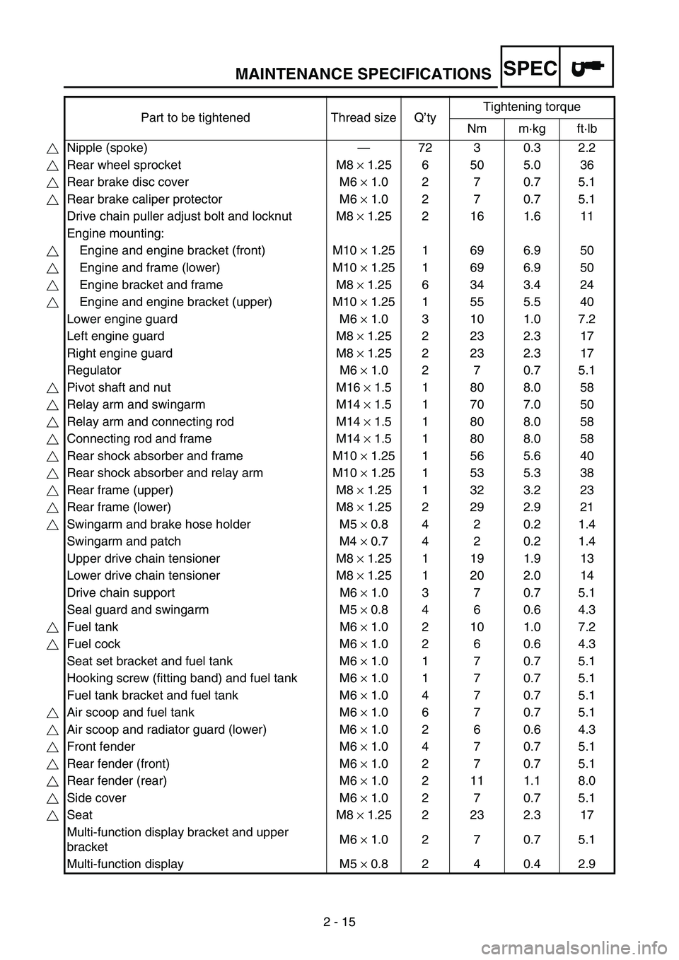
Part to be tightened Thread size Q’tyTightening torque
Nm m·kg ft·lb
Nipple (spoke)—72 3 0.3 2.2
Rear wheel sprocket M8 × 1.25 6 50 5.0 36
Rear brake disc cover M6 × 1.0 2 7 0.7 5.1
Rear brake caliper protector M6 × 1.0 2 7 0.7 5.1
Drive chain puller adjust bolt and locknut M8 × 1.25 2 16 1.6 11
Engine mounting:
Engine and engine bracket (front) M10 × 1.25 1 69 6.9 50
Engine and frame (lower) M10 × 1.25 1 69 6.9 50
Engine bracket and frame M8 × 1.25 6 34 3.4 24
Engine and engine bracket (upper) M10 × 1.25 1 55 5.5 40
Lower engine guard M6 × 1.0 3 10 1.0 7.2
Left engine guard M8 × 1.25 2 23 2.3 17
Right engine guard M8 × 1.25 2 23 2.3 17
Regulator M6 × 1.0 2 7 0.7 5.1
Pivot shaft and nut M16 × 1.5 1 80 8.0 58
Relay arm and swingarm M14 × 1.5 1 70 7.0 50
Relay arm and connecting rod M14 × 1.5 1 80 8.0 58
Connecting rod and frame M14 × 1.5 1 80 8.0 58
Rear shock absorber and frame M10 × 1.25 1 56 5.6 40
Rear shock absorber and relay arm M10 × 1.25 1 53 5.3 38
Rear frame (upper) M8 × 1.25 1 32 3.2 23
Rear frame (lower) M8 × 1.25 2 29 2.9 21
Swingarm and brake hose holder M5 × 0.8 4 2 0.2 1.4
Swingarm and patch M4 × 0.7 4 2 0.2 1.4
Upper drive chain tensioner M8 × 1.25 1 19 1.9 13
Lower drive chain tensioner M8 × 1.25 1 20 2.0 14
Drive chain support M6 × 1.0 3 7 0.7 5.1
Seal guard and swingarm M5 × 0.8 4 6 0.6 4.3
Fuel tank M6 × 1.0 2 10 1.0 7.2
Fuel cock M6 × 1.0 2 6 0.6 4.3
Seat set bracket and fuel tank M6 × 1.0 1 7 0.7 5.1
Hooking screw (fitting band) and fuel tank M6 × 1.0 1 7 0.7 5.1
Fuel tank bracket and fuel tank M6 × 1.0 4 7 0.7 5.1
Air scoop and fuel tank M6 × 1.0 6 7 0.7 5.1
Air scoop and radiator guard (lower) M6 × 1.0 2 6 0.6 4.3
Front fender M6 × 1.0 4 7 0.7 5.1
Rear fender (front) M6 × 1.0 2 7 0.7 5.1
Rear fender (rear) M6 × 1.0 2 11 1.1 8.0
Side cover M6 × 1.0 2 7 0.7 5.1
Seat M8 × 1.25 2 23 2.3 17
Multi-function display bracket and upper
bracketM6 × 1.0 2 7 0.7 5.1
Multi-function display M5 × 0.8 2 4 0.4 2.9
Page 159 of 900
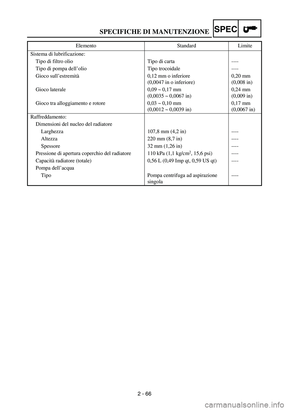
SPECIFICHE DI MANUTENZIONE
2 - 66
SPEC
Sistema di lubrificazione:
Tipo di filtro olio Tipo di carta ----
Tipo di pompa dell’olio Tipo trocoidale ----
Gioco sull’estremità0,12 mm o inferiore
(0,0047 in o inferiore)0,20 mm
(0,008 in)
Gioco laterale 0,09 ~ 0,17 mm
(0,0035 ~ 0,0067 in)0,24 mm
(0,009 in)
Gioco tra alloggiamento e rotore 0,03 ~ 0,10 mm
(0,0012 ~ 0,0039 in)0,17 mm
(0,0067 in)
Raffreddamento:
Dimensioni del nucleo del radiatore
Larghezza 107,8 mm (4,2 in) ----
Altezza 220 mm (8,7 in) ----
Spessore 32 mm (1,26 in) ----
Pressione di apertura coperchio del radiatore 110 kPa (1,1 kg/cm
2, 15,6 psi) ----
Capacità radiatore (totale) 0,56 L (0,49 Imp qt, 0,59 US qt) ----
Pompa dell’acqua
Tipo Pompa centrifuga ad aspirazione
singola---- Elemento Standard Limite