light YAMAHA WR 250F 2007 User Guide
[x] Cancel search | Manufacturer: YAMAHA, Model Year: 2007, Model line: WR 250F, Model: YAMAHA WR 250F 2007Pages: 912, PDF Size: 23.95 MB
Page 109 of 912

MAINTENANCE SPECIFICATIONS
2 - 16
SPEC
NOTE:
- marked portion shall be checked for torque tightening after break-in. Speed sensor lead holder and lower bracket M6 × 1.0 1 13 1.3 9.4
Headlight body and headlight unit—210.10.7
Headlight (left and right) M6 × 1.0 2 7 0.7 5.1
Taillight—310.10.7
Taillight lead clamp and rear fender—3 0.5 0.05 0.36
Catch tank (upper) M6 × 1.0 1 16 1.6 11
Catch tank (lower) M6 × 1.0 1 7 0.7 5.1
Footrest bracket and frame M10 × 1.25 4 55 5.5 40
Sidestand M10 × 1.25 1 25 2.5 18 Part to be tightened Thread size Q’tyTightening torque
Nm m·kg ft·lb
Page 110 of 912
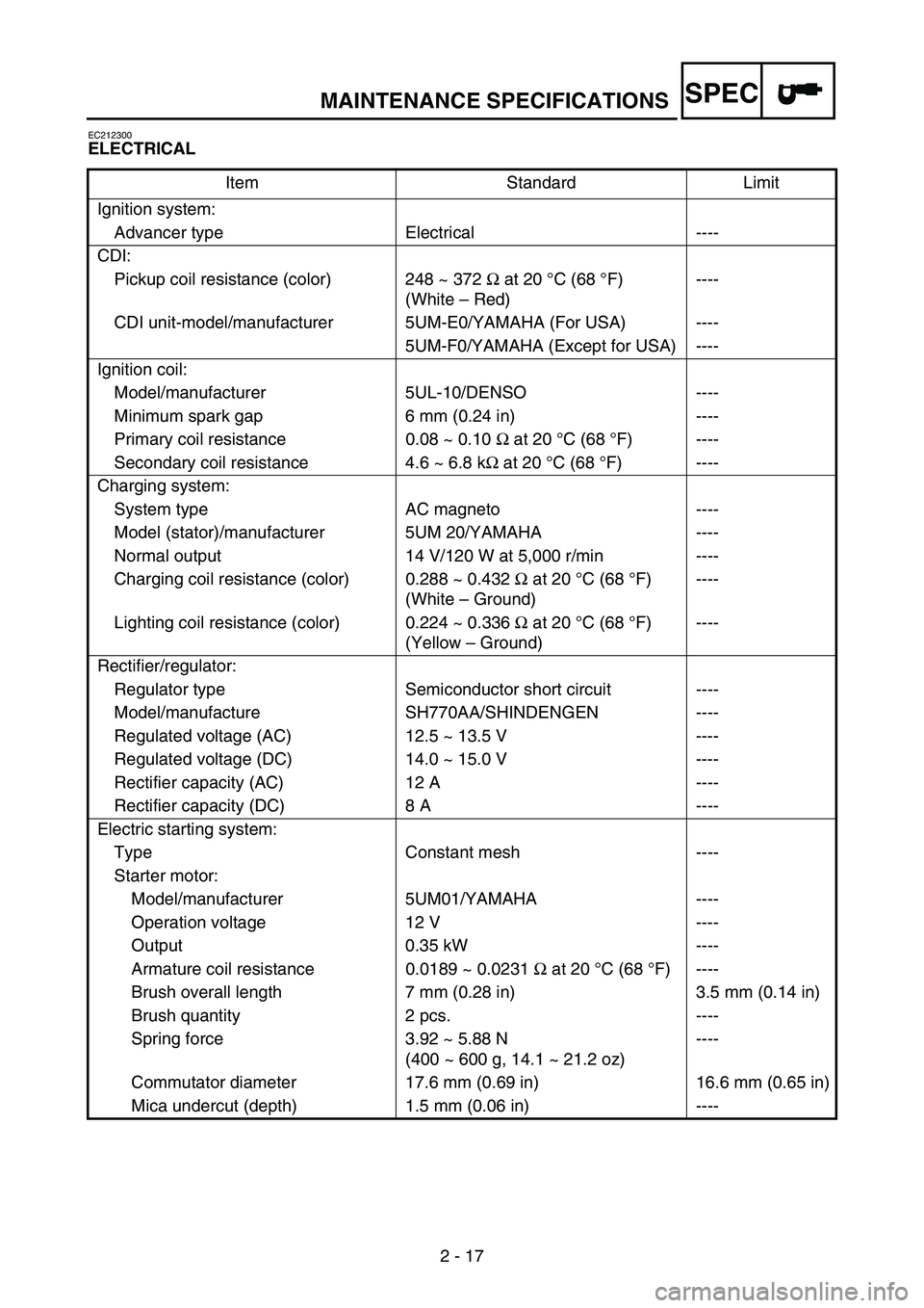
MAINTENANCE SPECIFICATIONS
2 - 17
SPEC
EC212300
ELECTRICAL
Item Standard Limit
Ignition system:
Advancer type Electrical ----
CDI:
Pickup coil resistance (color) 248 ~ 372 Ω at 20°C (68 °F)
(White – Red)----
CDI unit-model/manufacturer 5UM-E0/YAMAHA (For USA) ----
5UM-F0/YAMAHA (Except for USA) ----
Ignition coil:
Model/manufacturer 5UL-10/DENSO ----
Minimum spark gap 6 mm (0.24 in) ----
Primary coil resistance 0.08 ~ 0.10 Ω at 20 °C (68 °F) ----
Secondary coil resistance 4.6 ~ 6.8 kΩ at 20 °C (68 °F) ----
Charging system:
System type AC magneto ----
Model (stator)/manufacturer 5UM 20/YAMAHA ----
Normal output 14 V/120 W at 5,000 r/min ----
Charging coil resistance (color) 0.288 ~ 0.432 Ω at 20 °C (68 °F)
(White – Ground)----
Lighting coil resistance (color) 0.224 ~ 0.336 Ω at 20 °C (68 °F)
(Yellow – Ground)----
Rectifier/regulator:
Regulator type Semiconductor short circuit ----
Model/manufacture SH770AA/SHINDENGEN ----
Regulated voltage (AC) 12.5 ~ 13.5 V ----
Regulated voltage (DC) 14.0 ~ 15.0 V ----
Rectifier capacity (AC) 12 A ----
Rectifier capacity (DC) 8 A ----
Electric starting system:
Type Constant mesh ----
Starter motor:
Model/manufacturer 5UM01/YAMAHA ----
Operation voltage 12 V ----
Output 0.35 kW ----
Armature coil resistance 0.0189 ~ 0.0231 Ω at 20 °C (68 °F) ----
Brush overall length 7 mm (0.28 in) 3.5 mm (0.14 in)
Brush quantity 2 pcs. ----
Spring force 3.92 ~ 5.88 N
(400 ~ 600 g, 14.1 ~ 21.2 oz)----
Commutator diameter 17.6 mm (0.69 in) 16.6 mm (0.65 in)
Mica undercut (depth) 1.5 mm (0.06 in) ----
Page 198 of 912
2 - 105
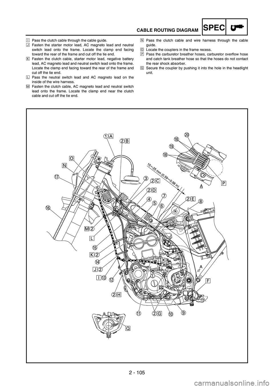
SPECCABLE ROUTING DIAGRAM
ÐPass the clutch cable through the cable guide.
ÑFasten the starter motor lead, AC magneto lead and neutral
switch lead onto the frame. Locate the clamp end facing
toward the rear of the frame and cut off the tie end.
ÒFasten the clutch cable, starter motor lead, negative battery
lead, AC magneto lead and neutral switch lead onto the frame.
Locate the clamp end facing toward the rear of the frame and
cut off the tie end.
ÓPass the neutral switch lead and AC magneto lead on the
inside of the wire harness.
ÔFasten the clutch cable, AC magneto lead and neutral switch
lead onto the frame. Locate the clamp end near the clutch
cable and cut off the tie end.ÕPass the clutch cable and wire harness through the cable
guide.
ÖLocate the couplers in the frame recess.
×Pass the carburetor breather hoses, carburetor overflow hose
and catch tank breather hose so that the hoses do not contact
the rear shock absorber.
ØSecure the coupler by pushing it into the hole in the headlight
unit.
Page 202 of 912
SPEC
2 - 109
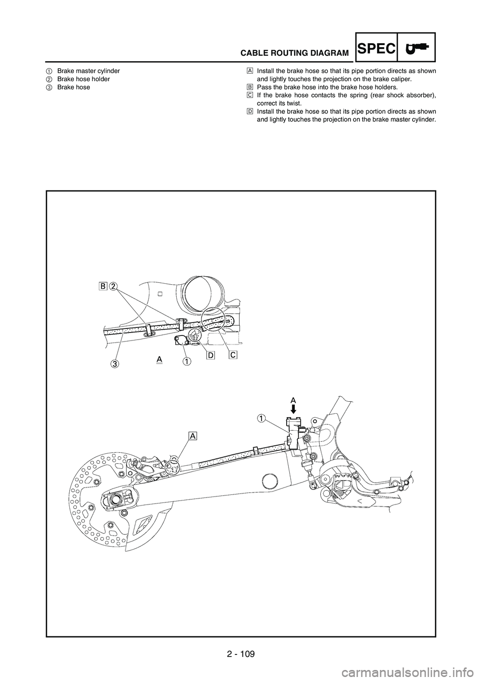
CABLE ROUTING DIAGRAM
1Brake master cylinder
2Brake hose holder
3Brake hoseÈInstall the brake hose so that its pipe portion directs as shown
and lightly touches the projection on the brake caliper.
ÉPass the brake hose into the brake hose holders.
ÊIf the brake hose contacts the spring (rear shock absorber),
correct its twist.
ËInstall the brake hose so that its pipe portion directs as shown
and lightly touches the projection on the brake master cylinder.
Page 204 of 912

SPEC
2 - 111
CABLE ROUTING DIAGRAM
1Clamp
2Positive battery lead
3Battery
4Negative battery lead
5Taillight coupler
6CDI unit coupler (6-pin)
7CDI unit coupler (3-pin)
8CDI unit coupler (6-pin)ÈFasten the wire harness, negative battery lead and starter
motor lead to the upper engine bracket (left side). Locate the
clamp end facing toward the upper side of the frame with the
tie end cut off on the inside of the frame.
ÉFasten the wire harness, negative battery lead and starter
motor lead to the upper engine bracket (left side). Locate the
clamp end facing toward the upper side of the frame with the
tie end cut off on the inside of the frame. Clamp the wire har-
ness and negative lead at the marking.
ÊPass the starter motor lead through the hole in the relay
holder.
ËFit the cover securely.
ÌConnect the wire harness to the starter relay.
Page 206 of 912

SPEC
2 - 113
CABLE ROUTING DIAGRAM
ÍFasten the catch tank breather hose
and catch tank hose to the rear frame.
Clamp them close to where they are
joined to the frame. Fasten the pipe
tightly enough not to crush it. Locate the
clamp end facing toward the rear of the
frame with the tie end facing downward.
ÎFasten the (three) CDI unit leads and
taillight lead to the rear frame. Locate
the clamp end facing toward the upper
side of the frame and cut off the tie end.
ÏConnect the negative battery lead to
the battery negative terminal.
ÐConnect the negative battery lead to
the wire harness.ÑFasten the wire harness to the rear
frame. Locate the clamp end facing
toward the upper side of the frame and
the tie end toward the inside of the
frame. Clamp the wire harness at the
marking.
ÒPass the wire harness, starter relay
lead, starting circuit cut-off relay lead
and negative battery lead through the
hole in the relay holder.
ÓFasten the (three) CDI unit leads and
taillight lead to the rear frame. Locate
the clamp end facing toward the lower
side of the frame and cut off the tie end.ÔFasten the taillight lead to the rear
frame. Locate the clamp end facing
toward the upper side of the frame and
cut off the time end.
ÕDo not allow the taillight lead to
slacken.
ÖLocate the CDI unit lead between the
CDI unit and rear fender.
×Locate the CDI unit coupler in the clear-
ance between the upper side of the CDI
unit and lower side of the catch tank
stay.
ØLocate the CDI unit lead between the
CDI unit and rear frame.
Page 208 of 912
2 - 115
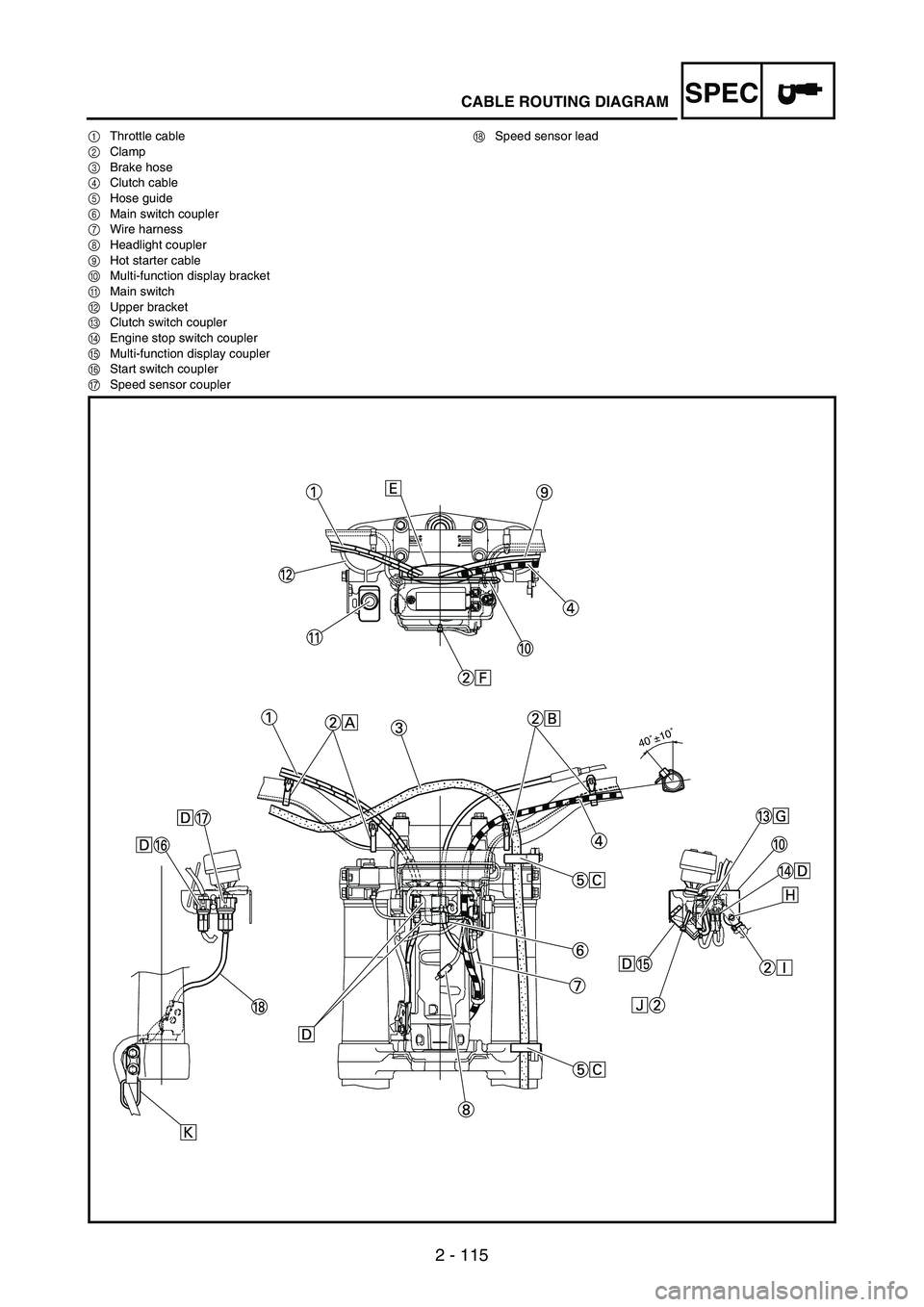
SPECCABLE ROUTING DIAGRAM
1Throttle cable
2Clamp
3Brake hose
4Clutch cable
5Hose guide
6Main switch coupler
7Wire harness
8Headlight coupler
9Hot starter cable
0Multi-function display bracket
AMain switch
BUpper bracket
CClutch switch coupler
DEngine stop switch coupler
EMulti-function display coupler
FStart switch coupler
GSpeed sensor couplerHSpeed sensor lead
40˚±10˚
Page 232 of 912
INSP
ADJ
3 - 21
EC350000
ENGINE
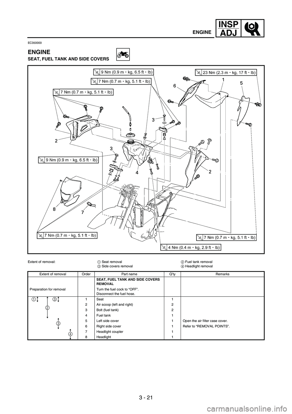
SEAT, FUEL TANK AND SIDE COVERS
Extent of removal:
1 Seat removal
2 Fuel tank removal
3 Side covers removal
4 Headlight removal
Extent of removal Order Part name Q’ty Remarks
SEAT, FUEL TANK AND SIDE COVERS
REMOVAL
Preparation for removal Turn the fuel cock to “OFF”.
Disconnect the fuel hose.
1Seat 1
2 Air scoop (left and right) 2
3 Bolt (fuel tank) 2
4 Fuel tank 1
5 Left side cover 1 Open the air filter case cover.
6 Right side cover 1 Refer to “REMOVAL POINTS”.
7 Headlight coupler 1
8 Headlight 1
2
13
4
3
ENGINE
Page 270 of 912
3 - 59
INSP
ADJ
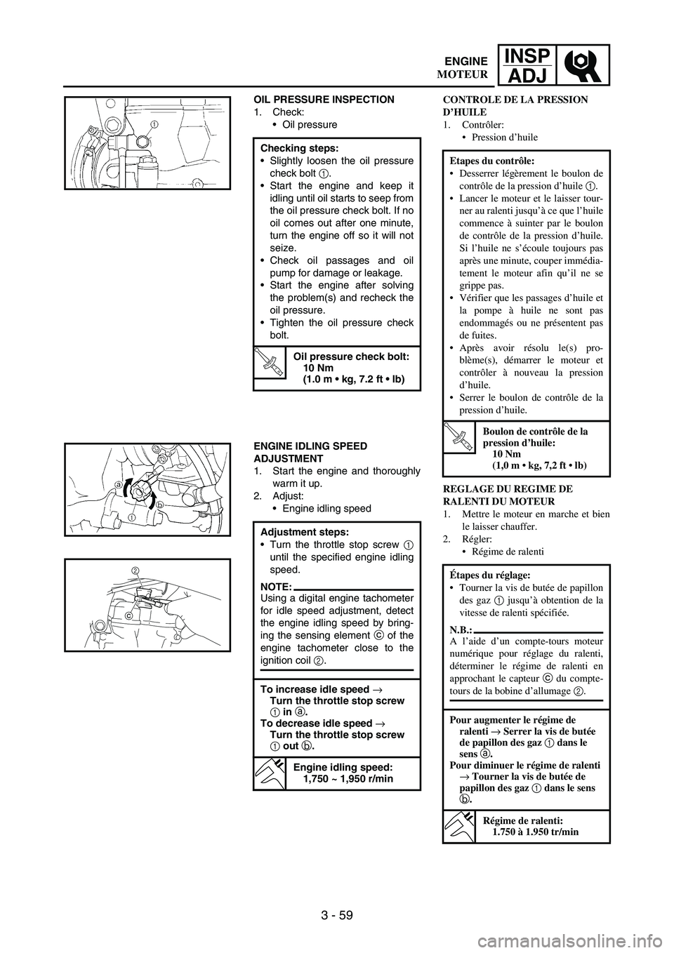
OIL PRESSURE INSPECTION
1. Check:
Oil pressure
Checking steps:
Slightly loosen the oil pressure
check bolt
1.
Start the engine and keep it
idling until oil starts to seep from
the oil pressure check bolt. If no
oil comes out after one minute,
turn the engine off so it will not
seize.
Check oil passages and oil
pump for damage or leakage.
Start the engine after solving
the problem(s) and recheck the
oil pressure.
Tighten the oil pressure check
bolt.
T R..
Oil pressure check bolt:
10 Nm
(1.0 m kg, 7.2 ft lb)
ENGINE IDLING SPEED
ADJUSTMENT
1. Start the engine and thoroughly
warm it up.
2. Adjust:
Engine idling speed
Adjustment steps:
Turn the throttle stop screw
1
until the specified engine idling
speed.
NOTE:Using a digital engine tachometer
for idle speed adjustment, detect
the engine idling speed by bring-
ing the sensing element
c of the
engine tachometer close to the
ignition coil
2.
To increase idle speed →
Turn the throttle stop screw
1 in a.
To decrease idle speed →
Turn the throttle stop screw
1 out b.
Engine idling speed:
1,750 ~ 1,950 r/min
c2
CONTROLE DE LA PRESSION
D’HUILE
1. Contrôler:
Pression d’huile
REGLAGE DU REGIME DE
RALENTI DU MOTEUR
1. Mettre le moteur en marche et bien
le laisser chauffer.
2. Régler:
Régime de ralenti Etapes du contrôle:
Desserrer légèrement le boulon de
contrôle de la pression d’huile 1.
Lancer le moteur et le laisser tour-
ner au ralenti jusqu’à ce que l’huile
commence à suinter par le boulon
de contrôle de la pression d’huile.
Si l’huile ne s’écoule toujours pas
après une minute, couper immédia-
tement le moteur afin qu’il ne se
grippe pas.
Vérifier que les passages d’huile et
la pompe à huile ne sont pas
endommagés ou ne présentent pas
de fuites.
Après avoir résolu le(s) pro-
blème(s), démarrer le moteur et
contrôler à nouveau la pression
d’huile.
Serrer le boulon de contrôle de la
pression d’huile.
T R..
Boulon de contrôle de la
pression d’huile:
10 Nm
(1,0 m kg, 7,2 ft lb)
Étapes du réglage:
Tourner la vis de butée de papillon
des gaz 1 jusqu’à obtention de la
vitesse de ralenti spécifiée.
N.B.:
A l’aide d’un compte-tours moteur
numérique pour réglage du ralenti,
déterminer le régime de ralenti en
approchant le capteur c du compte-
tours de la bobine d’allumage 2.
Pour augmenter le régime de
ralenti → Serrer la vis de butée
de papillon des gaz 1 dans le
sens a.
Pour diminuer le régime de ralenti
→ Tourner la vis de butée de
papillon des gaz 1 dans le sens
b.
Régime de ralenti:
1.750 à 1.950 tr/min
ENGINE
MOTEUR
Page 286 of 912
3 - 75
INSP
ADJ
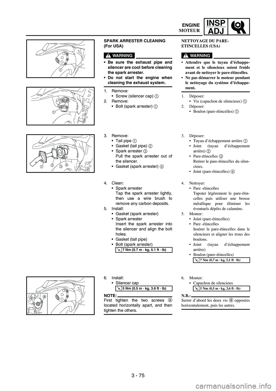
SPARK ARRESTER CLEANING
(For USA)
WARNING
Be sure the exhaust pipe and
silencer are cool before cleaning
the spark arrester.
Do not start the engine when
cleaning the exhaust system.
1. Remove:
Screw (silencer cap)
1
2. Remove:
Bolt (spark arrester)
1
1
1
3. Remove:
Tail pipe
1
Gasket (tail pipe)
2
Spark arrester 3
Pull the spark arrester out of
the silencer.
Gasket (spark arrester) 4
12
34
4. Clean:
Spark arrester
Tap the spark arrester lightly,
then use a wire brush to
remove any carbon deposits.
5. Install:
Gasket (spark arrester)
Spark arrester
Insert the spark arrester into
the silencer and align the bolt
holes.
Gasket (tail pipe)
Bolt (spark arrester)
T R..7 Nm (0.7 m · kg, 5.1 ft · lb)
6. Install:
Silencer cap
NOTE:First tighten the two screws a
located horizontally apart, and then
tighten the others.
T R..5 Nm (0.5 m · kg, 3.6 ft · lb)
aa
NETTOYAGE DU PARE-
ETINCELLES (USA)
WARNING
Attendre que le tuyau d’échappe-
ment et le silencieux soient froids
avant de nettoyer le pare-étincelles.
Ne pas démarrer le moteur pendant
le nettoyage du système d’échappe-
ment.
1. Déposer:
Vis (capuchon de silencieux) 1
2. Déposer:
Boulon (pare-étincelles) 1
3. Déposer:
Tuyau d’échappement arrière 1
Joint (tuyau d’échappement
arrière) 2
Pare-étincelles 3
Retirer le pare-étincelles du silen-
cieux.
Joint (pare-étincelles) 4
4. Nettoyer:
Pare -étincelles
Tapoter légèrement le pare-étin-
celles puis utiliser une brosse
métallique pour éliminer les
éventuels dépôts de calamine.
5. Monter:
Joint (pare-étincelles)
Pare -étincelles
Insérer le pare-étincelles dans le
silencieux et aligner les trous des
boulons.
Joint (tuyau d’échappement
arrière)
Boulon (pare-étincelles)
T R..7 Nm (0,7 m · kg, 5,1 ft · lb)
6. Monter:
Capuchon de silencieux
N.B.:
Serrer d’abord les deux vis a opposées
horizontalement, puis les autres.
T R..5 Nm (0,5 m · kg, 3,6 ft · lb)
ENGINE
MOTEUR