Oil YAMAHA WR 250F 2007 Owner's Manual
[x] Cancel search | Manufacturer: YAMAHA, Model Year: 2007, Model line: WR 250F, Model: YAMAHA WR 250F 2007Pages: 912, PDF Size: 23.95 MB
Page 111 of 912

MAINTENANCE SPECIFICATIONS
2 - 18
SPEC
NOTE:
Tighten the rotor nut to 65 Nm (6.5 m kg, 47 ft lb), loosen and retighten the rotor nut to 65 Nm
(6.5 m kg, 47 ft lb). Starter relay:
Model/manufacturer 2768090-A/JIDECO ----
Amperage rating 180 A ----
Coil winding resistance 4.2 ~ 4.6 Ω at 20 °C (68 °F) ----
Starting circuit cut-off relay:
Model/manufacturer ACM33221 M06/MATSUSHITA ----
Coil winding resistance 75.69 ~ 92.51 Ω at 20 °C (68 °F) ----
Fuse (amperage × quantity):
Main fuse 10 A × 1 ----
Reserve fuse 10 A × 1 ----
Part to be tightened Thread size Q’tyTightening torque
Nm m·kg ft·lb
Stator M5 × 0.8 2 7 0.7 5.1
Holder (AC magneto lead) M5 × 0.8 2 7 0.7 5.1
Rotor M12 × 1.25 1 Refer to NOTE.
Neutral switch M5 × 0.8 2 4 0.4 2.9
Starter motor M6 × 1.0 2 10 1.0 7.2
Starter relay terminal M6 × 1.0 2 4 0.4 2.9
Negative lead and cylinder head M6 × 1.0 1 10 1.0 7.2
Pickup coil M6 × 1.0 2 10 1.0 7.2 Item Standard Limit
Page 125 of 912
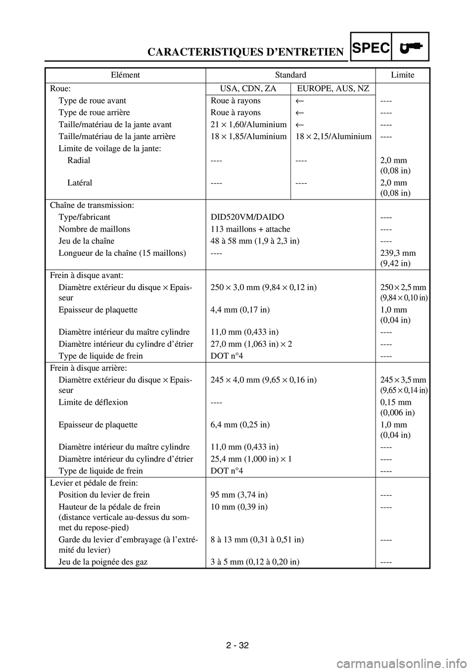
CARACTERISTIQUES D’ENTRETIEN
2 - 32
SPEC
Roue: USA, CDN, ZA EUROPE, AUS, NZ
Type de roue avant Roue à rayons← ----
Type de roue arrière Roue à rayons← ----
Taille/matériau de la jante avant 21 × 1,60/Aluminium← ----
Taille/matériau de la jante arrière 18 × 1,85/Aluminium 18 × 2,15/Aluminium ----
Limite de voilage de la jante:
Radial ---- ---- 2,0 mm
(0,08 in)
Latéral ---- ---- 2,0 mm
(0,08 in)
Chaîne de transmission:
Type/fabricant DID520VM/DAIDO ----
Nombre de maillons 113 maillons + attache ----
Jeu de la chaîne 48 à 58 mm (1,9 à 2,3 in) ----
Longueur de la chaîne (15 maillons) ---- 239,3 mm
(9,42 in)
Frein à disque avant:
Diamètre extérieur du disque × Epais-
seur250 × 3,0 mm (9,84 × 0,12 in) 250 × 2,5 mm
(9,84 × 0,10 in)
Epaisseur de plaquette 4,4 mm (0,17 in) 1,0 mm
(0,04 in)
Diamètre intérieur du maître cylindre 11,0 mm (0,433 in) ----
Diamètre intérieur du cylindre d’étrier 27,0 mm (1,063 in) × 2 ----
Type de liquide de frein DOT n°4 ----
Frein à disque arrière:
Diamètre extérieur du disque × Epais-
seur245 × 4,0 mm (9,65 × 0,16 in) 245 × 3,5 mm
(9,65 × 0,14 in)
Limite de déflexion ---- 0,15 mm
(0,006 in)
Epaisseur de plaquette 6,4 mm (0,25 in) 1,0 mm
(0,04 in)
Diamètre intérieur du maître cylindre 11,0 mm (0,433 in) ----
Diamètre intérieur du cylindre d’étrier 25,4 mm (1,000 in) × 1 ----
Type de liquide de frein DOT n°4 ----
Levier et pédale de frein:
Position du levier de frein 95 mm (3,74 in) ----
Hauteur de la pédale de frein
(distance verticale au-dessus du som-
met du repose-pied)10 mm (0,39 in) ----
Garde du levier d’embrayage (à l’extré-
mité du levier)8 à 13 mm (0,31 à 0,51 in) ----
Jeu de la poignée des gaz 3 à 5 mm (0,12 à 0,20 in) ---- Elément Standard Limite
Page 190 of 912
SPEC
2 - 97
LUBRICATION DIAGRAMS
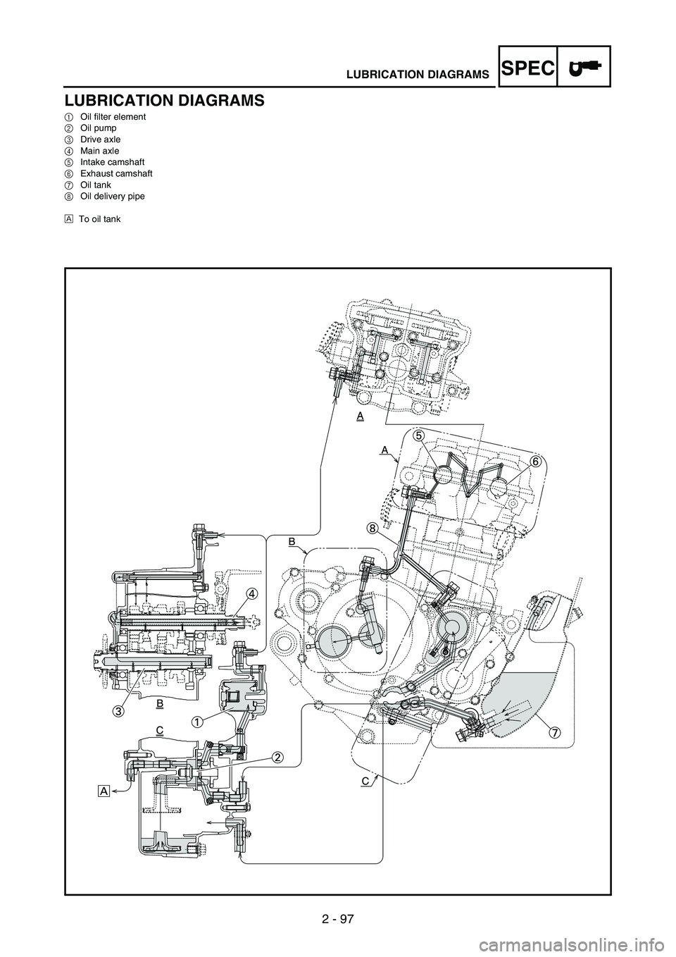
LUBRICATION DIAGRAMS
1Oil filter element
2Oil pump
3Drive axle
4Main axle
5Intake camshaft
6Exhaust camshaft
7Oil tank
8Oil delivery pipe
ÈTo oil tank
Page 192 of 912
SPEC
2 - 99
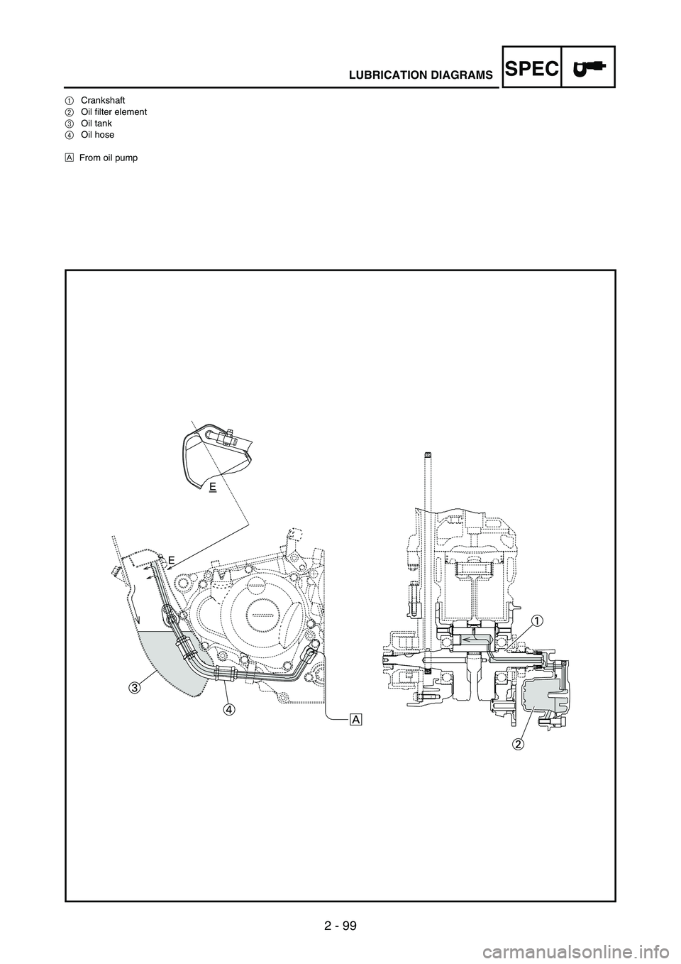
LUBRICATION DIAGRAMS
1Crankshaft
2Oil filter element
3Oil tank
4Oil hose
ÈFrom oil pump
Page 194 of 912
2 - 101
SPECCABLE ROUTING DIAGRAM
EC240000
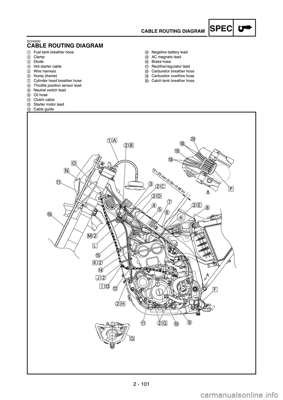
CABLE ROUTING DIAGRAM
1Fuel tank breather hose
2Clamp
3Diode
4Hot starter cable
5Wire harness
6Hump (frame)
7Cylinder head breather hose
8Throttle position sensor lead
9Neutral switch lead
0Oil hose
AClutch cable
BStarter motor lead
CCable guideDNegative battery lead
EAC magneto lead
FBrake hose
GRectifier/regulator lead
HCarburetor breather hose
ICarburetor overflow hose
JCatch tank breather hose
Page 196 of 912

2 - 103
SPECCABLE ROUTING DIAGRAM
ÈInsert the end of the fuel tank breather hose into the hole in the
steering stem.
ÉFasten the throttle cable, hot starter cable and rectifier/regula-
tor lead onto the frame. Locate the clamp end facing the lower
side of the hot starter cable and cut off the tie end.
ÊFasten the diode (at the marking), throttle cable and hot starter
cable onto the frame. Locate the clamp end facing toward the
lower right of the frame and with the tie end facing downward.
ËFasten the wire harness, throttle position sensor lead, starter
motor lead and negative battery lead onto the frame. Pass the
clamp through the hole in the stay (air cut-off valve). Locate the
clamp end facing toward the lower side of the frame and cut off
the tie end.ÌFasten the throttle position sensor lead onto the frame. Locate
the clamp end facing toward the lower side of the frame and
cut off the tie end.
ÍPass the carburetor breather hoses, carburetor overflow hose
and catch tank breather hose between the connecting rod and
cross tube (frame).
ÎFasten the neutral switch lead and oil hose together with the
plastic locking ties and cut off the tie ends.
ÏFasten the neutral switch lead and AC magneto lead onto the
frame. Locate the clamp end facing toward the outside of the
frame and tie end facing toward the rear of the frame.
Page 200 of 912
2 - 107
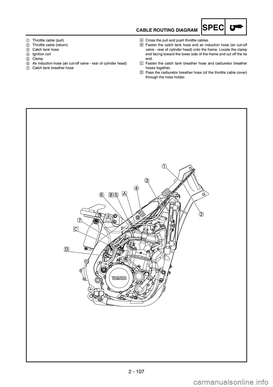
SPECCABLE ROUTING DIAGRAM
1Throttle cable (pull)
2Throttle cable (return)
3Catch tank hose
4Ignition coil
5Clamp
6Air induction hose (air cut-off valve - rear of cylinder head)
7Catch tank breather hoseÈCross the pull and push throttle cables.
ÉFasten the catch tank hose and air induction hose (air cut-off
valve - rear of cylinder head) onto the frame. Locate the clamp
end facing toward the lower side of the frame and cut off the tie
end.
ÊFasten the catch tank breather hose and carburetor breather
hoses together.
ËPass the carburetor breather hose (of the throttle cable cover)
through the hose holder.
Page 212 of 912
3 - 1
INSP
ADJ
MAINTENANCE INTERVALS
EC300000
REGULAR INSPECTION AND ADJUSTMENTS
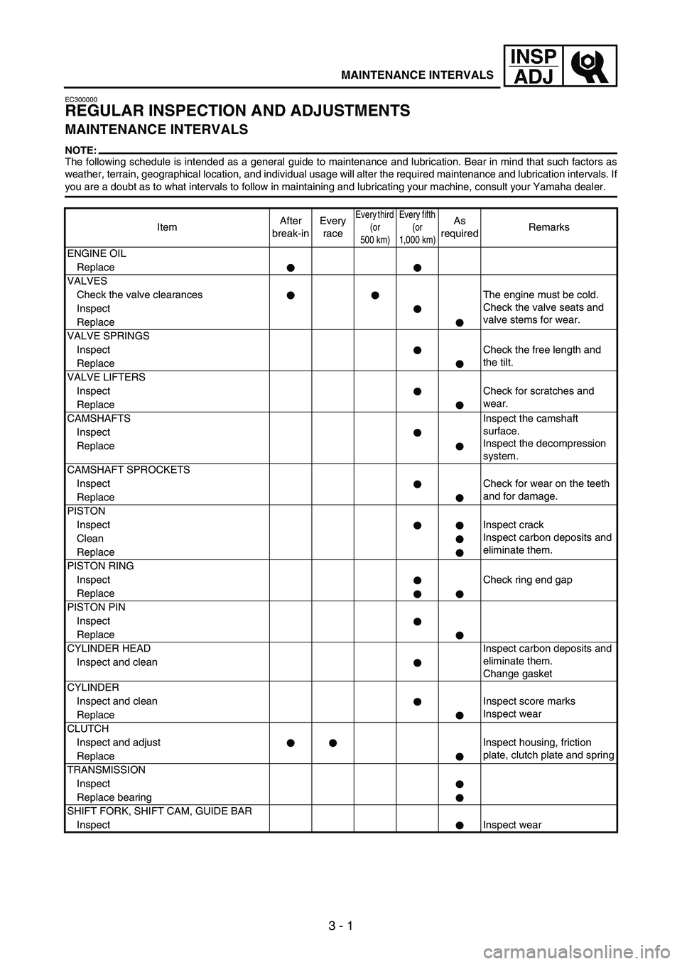
MAINTENANCE INTERVALS
NOTE:The following schedule is intended as a general guide to maintenance and lubrication. Bear in mind that such factors as
weather, terrain, geographical location, and individual usage will alter the required maintenance and lubrication intervals. If
you are a doubt as to what intervals to follow in maintaining and lubricating your machine, consult your Yamaha dealer.
ItemAfter
break-inEvery
race
Every third
(or
500 km)Every fifth
(or
1,000 km)As
requiredRemarks
ENGINE OIL
Replace
VALVES
Check the valve clearances The engine must be cold.
Check the valve seats and
valve stems for wear. Inspect
Replace
VALVE SPRINGS
InspectCheck the free length and
the tilt.
Replace
VALVE LIFTERS
InspectCheck for scratches and
wear.
Replace
CAMSHAFTSInspect the camshaft
surface.
Inspect the decompression
system. Inspect
Replace
CAMSHAFT SPROCKETS
InspectCheck for wear on the teeth
and for damage.
Replace
PISTON
InspectInspect crack
Inspect carbon deposits and
eliminate them. Clean
Replace
PISTON RING
InspectCheck ring end gap
Replace
PISTON PIN
Inspect
Replace
CYLINDER HEADInspect carbon deposits and
eliminate them.
Change gasket Inspect and clean
CYLINDER
Inspect and clean Inspect score marks
Inspect wear
Replace
CLUTCH
Inspect and adjust Inspect housing, friction
plate, clutch plate and spring
Replace
TRANSMISSION
Inspect
Replace bearing
SHIFT FORK, SHIFT CAM, GUIDE BAR
InspectInspect wear
Page 213 of 912
3 - 2
INSP
ADJ
MAINTENANCE INTERVALS
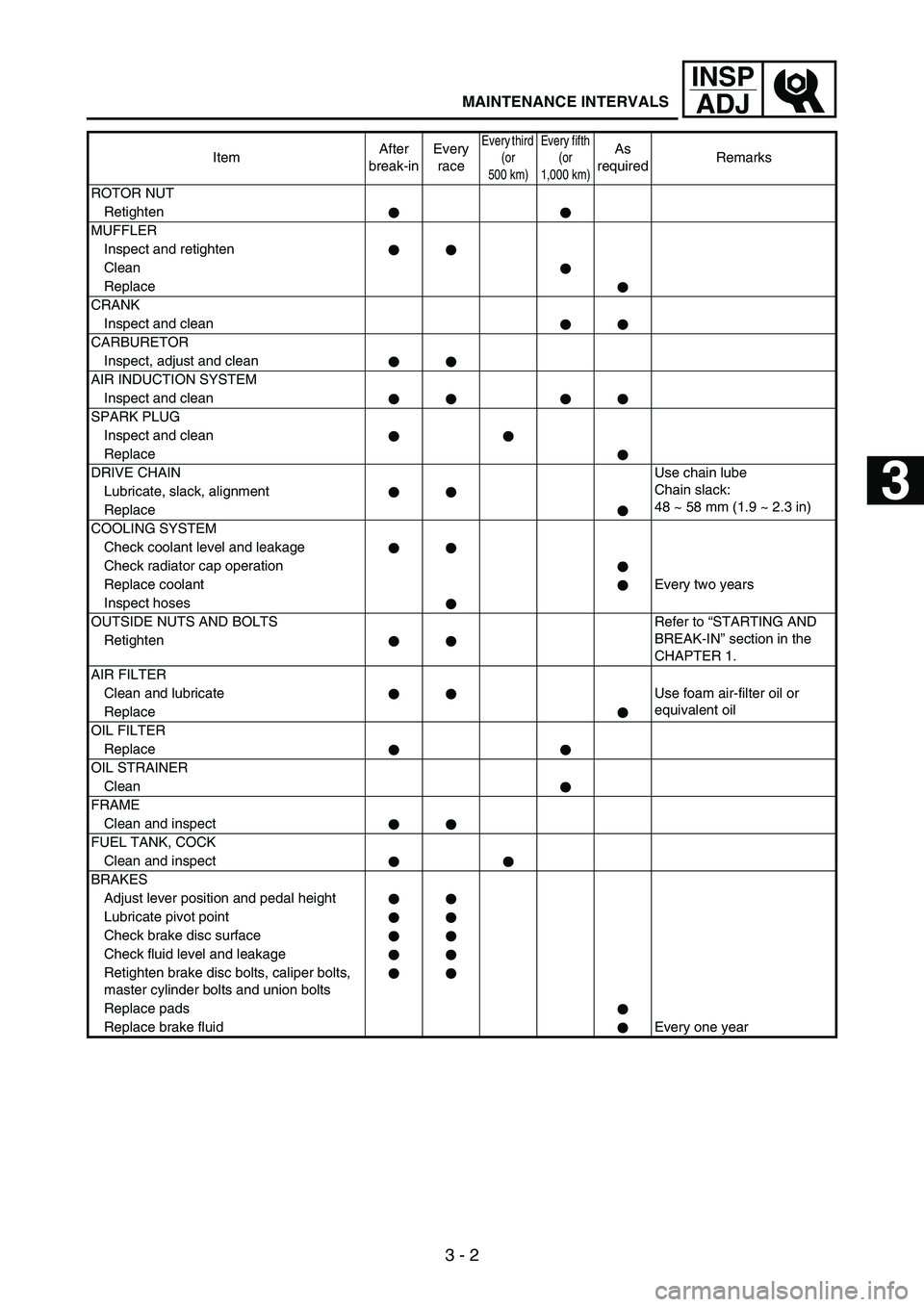
ROTOR NUT
Retighten
MUFFLER
Inspect and retighten
Clean
Replace
CRANK
Inspect and clean
CARBURETOR
Inspect, adjust and clean
AIR INDUCTION SYSTEM
Inspect and clean
SPARK PLUG
Inspect and clean
Replace
DRIVE CHAINUse chain lube
Chain slack:
48 ~ 58 mm (1.9 ~ 2.3 in) Lubricate, slack, alignment
Replace
COOLING SYSTEM
Check coolant level and leakage
Check radiator cap operation
Replace coolantEvery two years
Inspect hoses
OUTSIDE NUTS AND BOLTS Refer to “STARTING AND
BREAK-IN” section in the
CHAPTER 1. Retighten
AIR FILTER
Clean and lubricate Use foam air-filter oil or
equivalent oil
Replace
OIL FILTER
Replace
OIL STRAINER
Clean
FRAME
Clean and inspect
FUEL TANK, COCK
Clean and inspect
BRAKES
Adjust lever position and pedal height
Lubricate pivot point
Check brake disc surface
Check fluid level and leakage
Retighten brake disc bolts, caliper bolts,
master cylinder bolts and union bolts
Replace pads
Replace brake fluid Every one yearItemAfter
break-inEvery
race
Every third
(or
500 km)Every fifth
(or
1,000 km)As
requiredRemarks
1
2
3
4
5
6
7
Page 214 of 912
3 - 3
INSP
ADJ
MAINTENANCE INTERVALS
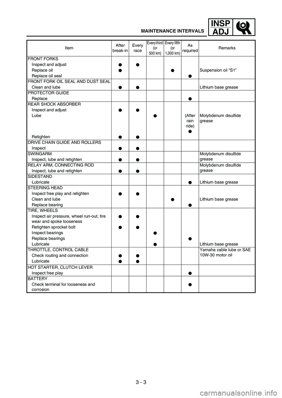
FRONT FORKS
Inspect and adjust
Replace oilSuspension oil “S1”
Replace oil seal
FRONT FORK OIL SEAL AND DUST SEAL
Clean and lubeLithium base grease
PROTECTOR GUIDE
Replace
REAR SHOCK ABSORBER
Inspect and adjust
Lube(After
rain
ride)Molybdenum disulfide
grease
Retighten
DRIVE CHAIN GUIDE AND ROLLERS
Inspect
SWINGARMMolybdenum disulfide
grease
Inspect, lube and retighten
RELAY ARM, CONNECTING ROD Molybdenum disulfide
grease
Inspect, lube and retighten
SIDESTAND
LubricateLithium base grease
STEERING HEAD
Inspect free play and retighten
Clean and lubeLithium base grease
Replace bearing
TIRE, WHEELS
Inspect air pressure, wheel run-out, tire
wear and spoke looseness
Retighten sprocket bolt
Inspect bearings
Replace bearings
LubricateLithium base grease
THROTTLE, CONTROL CABLE Yamaha cable lube or SAE
10W-30 motor oil
Check routing and connection
Lubricate
HOT STARTER, CLUTCH LEVER
Inspect free play
BATTERY
Check terminal for looseness and
corrosionItemAfter
break-inEvery
race
Every third
(or
500 km)Every fifth
(or
1,000 km)As
requiredRemarks