display YAMAHA WR 250F 2007 Owner's Manual
[x] Cancel search | Manufacturer: YAMAHA, Model Year: 2007, Model line: WR 250F, Model: YAMAHA WR 250F 2007Pages: 912, PDF Size: 23.95 MB
Page 208 of 912
2 - 115
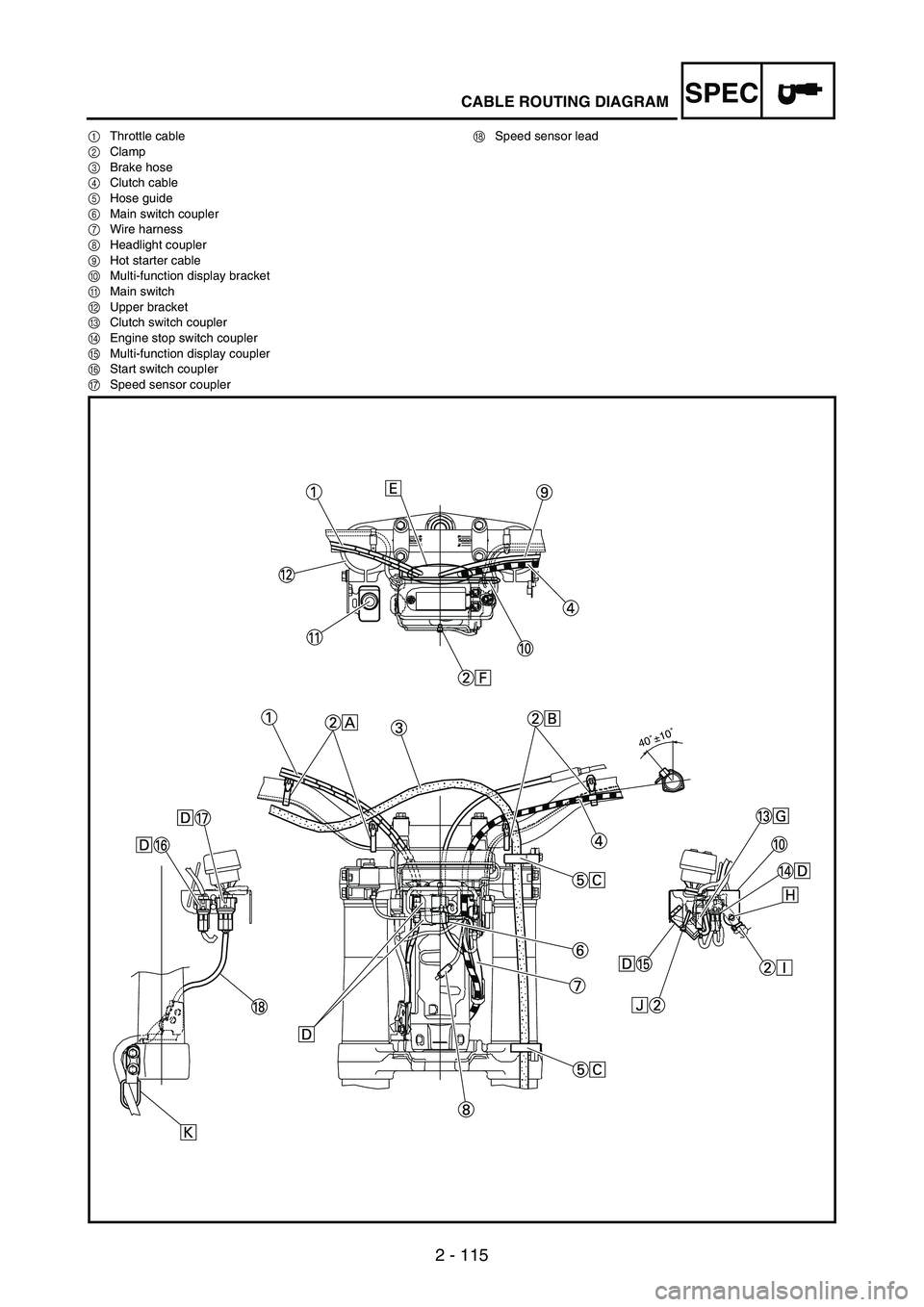
SPECCABLE ROUTING DIAGRAM
1Throttle cable
2Clamp
3Brake hose
4Clutch cable
5Hose guide
6Main switch coupler
7Wire harness
8Headlight coupler
9Hot starter cable
0Multi-function display bracket
AMain switch
BUpper bracket
CClutch switch coupler
DEngine stop switch coupler
EMulti-function display coupler
FStart switch coupler
GSpeed sensor couplerHSpeed sensor lead
40˚±10˚
Page 209 of 912

2 - 116
SPEC
1Câble des gaz
2Collier à pince
3Durit de frein
4Câble d’embrayage
5Guide de durit
6Fiche rapide du contacteur à clé
7Faisceau de fils
8Fiche rapide du phare
9Câble de starter à chaud
0Support de l’écran multifonction
AContacteur à clé
BTé supérieur
CFiche rapide du contacteur d’embrayage
DFiche rapide du coupe-circuit du moteur
EFiche rapide de l’écran multifonction
FFiche rapide du contacteur de démarrageGFiche rapide du capteur de vitesse
HFil du capteur de vitesse
1Gaszug
2Klemme
3Bremsschlauch
4Kupplungszug
5Schlauchführung
6Zündschloss-Steckverbinder
7Kabelbaum
8Scheinwerfer-Steckverbinder
9Warmstartzug
0Multifunktionsanzeigen-Halterung
AZündschloss
BObere Gabelbrücke
CKupplungsschalter-Steckverbinder
DMotorstoppschalter-Steckverbinder
EMultifunktionsanzeigen-Steckverbinder
FStarterschalter-SteckverbinderGGeschwindigkeitssensor-Steckverbinder
HGeschwindigkeitssensor-Kabel
1Cavo acceleratore
2Morsetto
3Tubo del freno
4Cavo frizione
5Guida flessibile
6Accoppiatore interruttore di accensione
7Cablaggio elettrico
8Accoppiatore del faro
9Cavo starter per partenze a caldo
0Staffa display multifunzione
AInterruttore di accensione
BStaffa superiore
CAccoppiatore interruttore della frizione
DAccoppiatore interruttore di arresto motore
EAccoppiatore display multifunzione
FAccoppiatore interruttore dell’avviamentoGAccoppiatore sensore velocità
HCavo sensore velocità
1Cable del acelerador
2Brida
3Tubo de freno
4Cable de embrague
5Guía de tubo
6Acoplador del interruptor principal
7Mazo de cables
8Acoplador del faro
9Cable de arranque en caliente
0Soporte del visor multifunción
AInterruptor principal
BSoporte superior
CAcoplador del interruptor del embrague
DAcoplador del interruptor de paro del motor
EAcoplador del visor multifunción
FAcoplador del interruptor de arranqueGAcoplador del sensor de velocidad
HCable del sensor de velocidad
DIAGRAMME DE CHEMINEMENT DES CABLES
KABELFÜHRUNGS-SCHAUBILD
SCHEMA PERCORSO DEI CAVI
DIAGRAMA DE CABLEADO
Page 210 of 912
2 - 117
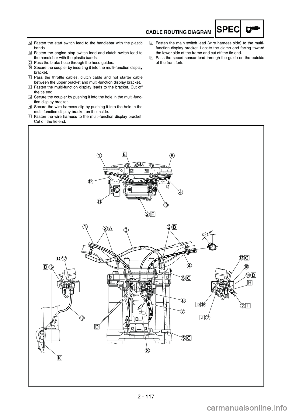
SPECCABLE ROUTING DIAGRAM
ÈFasten the start switch lead to the handlebar with the plastic
bands.
ÉFasten the engine stop switch lead and clutch switch lead to
the handlebar with the plastic bands.
ÊPass the brake hose through the hose guides.
ËSecure the coupler by inserting it into the multi-function display
bracket.
ÌPass the throttle cables, clutch cable and hot starter cable
between the upper bracket and multi-function display bracket.
ÍFasten the multi-function display leads to the bracket. Cut off
the tie end.
ÎSecure the coupler by pushing it into the hole in the multi-func-
tion display bracket.
ÏSecure the wire harness clip by pushing it into the hole in the
multi-function display bracket on the inside.
ÐFasten the wire harness to the multi-function display bracket.
Cut off the tie end.ÑFasten the main switch lead (wire harness side) to the multi-
function display bracket. Locate the clamp end facing toward
the lower side of the frame and cut off the tie end.
ÒPass the speed sensor lead through the guide on the outside
of the front fork.
40˚±10˚
Page 211 of 912

2 - 118
SPEC
ÈFixer le fil du contacteur du démarreur au guidon à l’aide des bandes
en plastique.
ÉFixer le fil du coupe-circuit du moteur et le fil du contacteur
d’embrayage au guidon à l’aide des bandes en plastique.
ÊAcheminer la durit de frein dans les guides de durit.
ËFixer la fiche rapide en l’insérant dans le support de l’écran multi-
fonction.
ÌAcheminer les câbles des gaz, le câble d’embrayage et le câble de
starter à chaud entre le té supérieur et le support de l’écran multi-
fonction.
ÍFixer les fils de l’écran multifonction au support. Couper l’extrémité
du collier.
ÎFixer la fiche rapide en l’enfonçant dans l’orifice du support de
l’écran multifonction.
ÏFixer le clip du faisceau de fils en l’enfonçant dans l’orifice du sup-
port de l’écran multifonction à l’intérieur.ÐFixer le faisceau de fils au support de l’écran multifonction. Couper
l’extrémité du collier.
ÑFixer le fil du contacteur à clé (côté faisceau de fils) au support de
l’écran multifonction. Rechercher l’extrémité du collier à pince
orienté vers le côté inférieur du cadre et couper l’extrémité du col-
lier.
ÒAcheminer le fil du capteur de vitesse par le guide à l’extérieur de la
fourche.
ÈDas Starter-Kabel mit Kunststoffbindern am Lenker befesti-
gen.
ÉDie Motorstoppschalter- und Kupplungsschalter-Kabel mit
Kunststoffbindern am Lenker befestigen.
ÊDen Bremsschlauch durch die Schlauchführungen leiten.
ËDen Steckverbinder in die Multifunktionsanzeigen-Halterung
einsetzen.
ÌDie Gas-, Kupplungs- und Warmstartzüge zwischen der obe-
ren Gabelbrücke und der Multifunktionsanzeigen-Halterung
verlegen.
ÍDie Multifunktionsanzeigen-Kabel an der Halterung befesti-
gen. Kabelbinderende abschneiden.
ÎDen Steckverbinder in die Öffnung in der Multifunktionsanzei-
gen-Halterung einsetzen.
ÏDen Kabelbaum-Clip von innen in die entsprechende Öffnung
in der Multifunktionsanzeigen-Halterung einsetzen.ÐKabelbaum an der Multifunktionsanzeigen-Halterung befesti-
gen. Kabelbinderende abschneiden.
ÑZündschloss-Kabel (kabelbaumseitig) an der Multifunktions-
anzeigen-Halterung befestigen. Klemmenende so positionie-
ren, dass es in Richtung unterer Rahmen zeigt und
überstehendes Kabelbinderende abschneiden.
ÒDas Geschwindigkeitssensor-Kabel durch die Führung an der
Außenseite des Gabelrohrs verlegen.
ÈFissare il cavo dell’interruttore di avviamento al manubrio con le
fascette in plastica.
ÉFissare il cavo interruttore di arresto motore e il cavo interruttore
della frizione al manubrio con le fascette in plastica.
ÊFar passare il tubo del freno attraverso le relative guide.
ËFissare l’accoppiatore inserendolo nel supporto del display multifun-
zione.
ÌFar passare il cavo acceleratore, il cavo della frizione e il cavo starter
per partenze a caldo tra la staffa superiore e il supporto del display
multifunzione.
ÍFissare i cavi del display multifunzione al supporto. Tagliare l’estre-
mità dei serrafili.
ÎFissare l’accoppiatore spingendolo nel foro del supporto del display
multifunzione.
ÏFissare il fermo del cablaggio elettrico spingendolo nel foro del sup-
porto del display multifunzione sulla parte interna.ÐFissare il cablaggio elettrico al supporto del display multifunzione.
Tagliare l’estremità dei serrafili.
ÑFissare il cavo dell’interruttore di accensione (lato cablaggio elet-
trico) al supporto del display multifunzione. Posizionare l’estremità
del morsetto rivolgendola verso la parte inferiore del telaio e tagliare
l’estremità dei serrafili.
ÒFar passare il cavo sensore velocità attraverso la guida sulla parte
esterna della forcella anteriore.
ÈSujete el cable del interruptor de arranque al manillar con las
bandas de plástico.
ÉSujete el cable del interruptor de paro del motor y el cable del
interruptor del embrague al manillar con las bandas de
plástico.
ÊPase el tubo de freno por las guías de tubo.
ËSujete el acoplador introduciéndolo en el soporte del visor
multifunción.
ÌPase los cables del acelerador, el cable de embrague y el
cable de arranque en caliente entre el soporte superior y el
soporte del visor multifunción.
ÍSujete los cables del visor multifunción al soporte. Corte el
extremo.
ÎSujete el acoplador empujándolo al interior del orificio del
soporte del visor multifunción.ÏSujete el clip del mazo de cables empujándolo al interior del
orificio del soporte del visor multifunción por el lado interior.
ÐSujete el mazo de cables al soporte del visor multifunción.
Corte el extremo.
ÑSujete el cable del interruptor principal (por el lado del mazo
de cables) al soporte del visor multifunción. Localice el
extremo de la brida encarada hacia la parte inferior del
bastidor y corte el extremo.
ÒPase el cable del sensor de velocidad por la guía en el lado
exterior de la horquilla delantera.
DIAGRAMME DE CHEMINEMENT DES CABLES
KABELFÜHRUNGS-SCHAUBILD
SCHEMA PERCORSO DEI CAVI
DIAGRAMA DE CABLEADO
Page 768 of 912
6 - 105
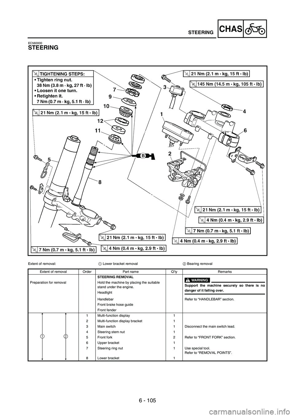
CHASSTEERING
EC560000
STEERING
Extent of removal:
1 Lower bracket removal
2 Bearing removal
Extent of removal Order Part name Q’ty Remarks
STEERING REMOVAL
WARNING
Support the machine securely so there is nodanger of it falling over. Preparation for removal Hold the machine by placing the suitable
stand under the engine.
Headlight
Handlebar Refer to “HANDLEBAR” section.
Front brake hose guide
Front fender
1 Multi-function display 1
2 Multi-function display bracket 1
3 Main switch 1 Disconnect the main switch lead.
4 Steering stem nut 1
5 Front fork 2 Refer to “FRONT FORK” section.
6 Upper bracket 1
7 Steering ring nut 1 Use special tool.
Refer to “REMOVAL POINTS”.
8 Lower bracket 1
12
Page 770 of 912
6 - 107
CHAS
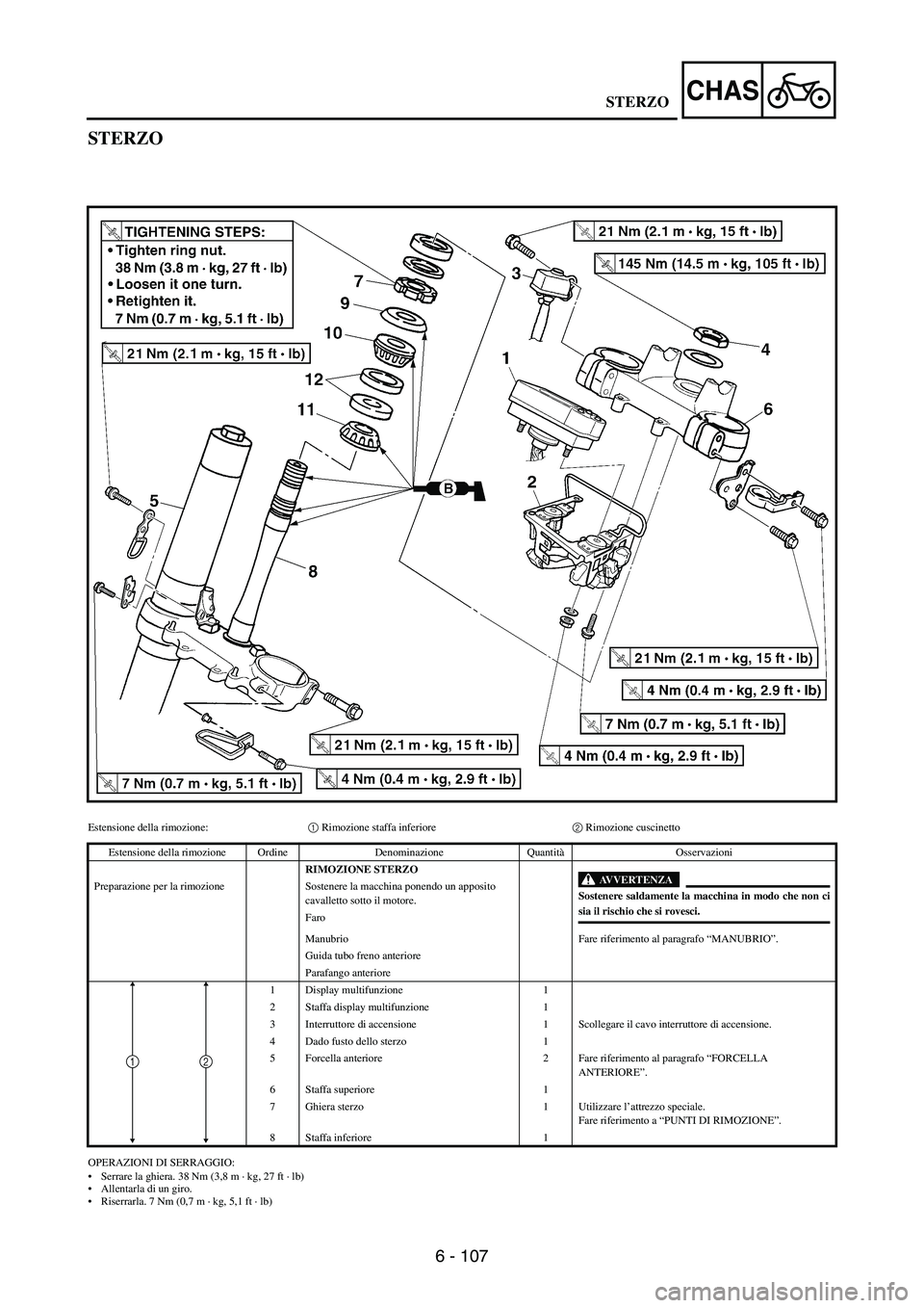
STERZO
Estensione della rimozione:1 Rimozione staffa inferiore2 Rimozione cuscinetto
OPERAZIONI DI SERRAGGIO:
Serrare la ghiera. 38 Nm (3,8 m · kg, 27 ft · lb)
Allentarla di un giro.
Riserrarla. 7 Nm (0,7 m · kg, 5,1 ft · lb) Estensione della rimozione Ordine Denominazione QuantitàOsservazioni
RIMOZIONE STERZO
AVVERTENZA
Sostenere saldamente la macchina in modo che non cisia il rischio che si rovesci. Preparazione per la rimozione Sostenere la macchina ponendo un apposito
cavalletto sotto il motore.
Faro
Manubrio Fare riferimento al paragrafo “MANUBRIO”.
Guida tubo freno anteriore
Parafango anteriore
1 Display multifunzione 1
2 Staffa display multifunzione 1
3 Interruttore di accensione 1 Scollegare il cavo interruttore di accensione.
4 Dado fusto dello sterzo 1
5 Forcella anteriore 2 Fare riferimento al paragrafo “FORCELLA
ANTERIORE”.
6 Staffa superiore 1
7 Ghiera sterzo 1 Utilizzare l’attrezzo speciale.
Fare riferimento a “PUNTI DI RIMOZIONE”.
8 Staffa inferiore 1
12
STERZO
Page 782 of 912
6 - 119
CHASSTEERING
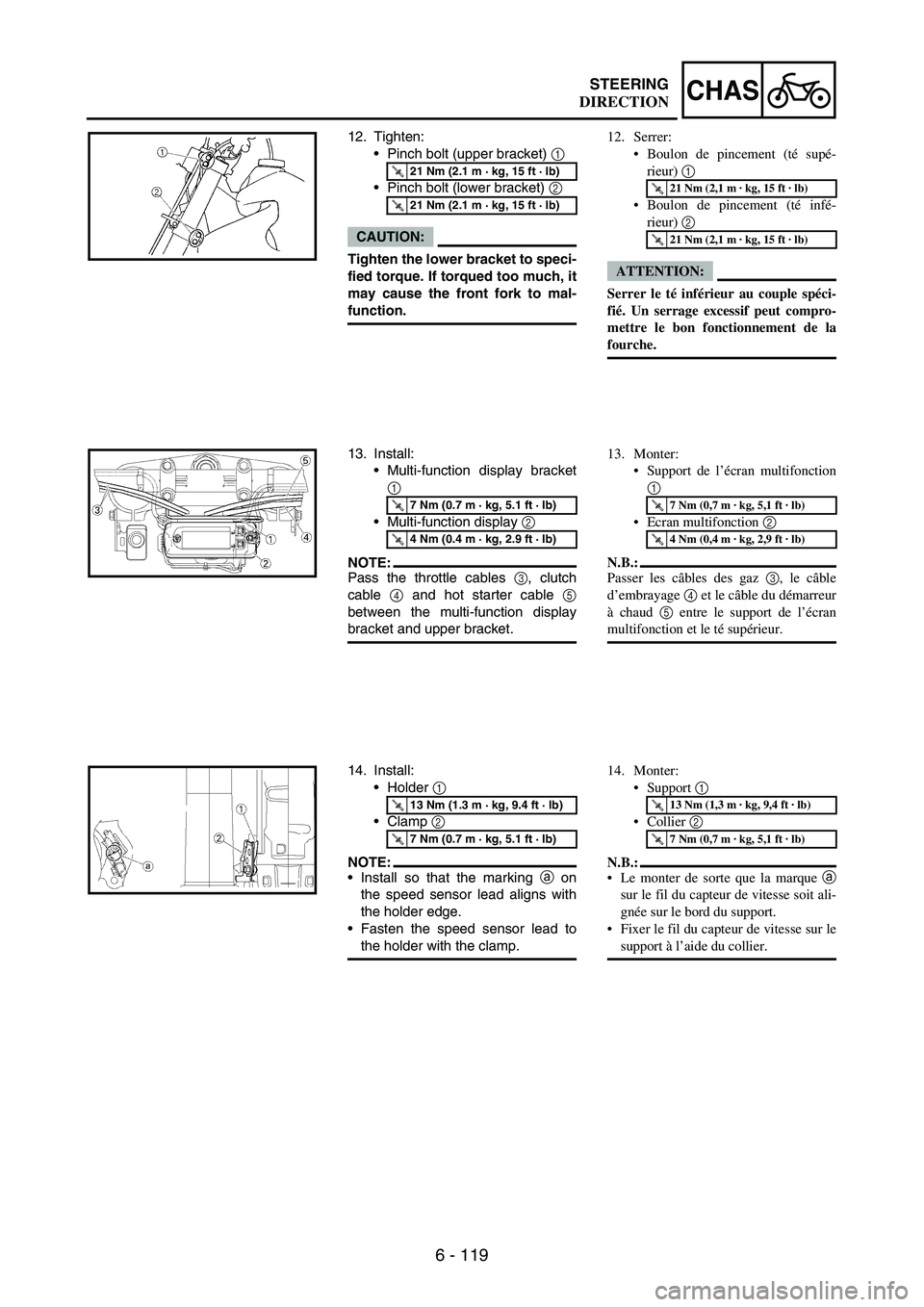
12. Tighten:
•Pinch bolt (upper bracket)
1
•Pinch bolt (lower bracket)
2
CAUTION:
Tighten the lower bracket to speci-
fied torque. If torqued too much, it
may cause the front fork to mal-
function.
T R..21 Nm (2.1 m · kg, 15 ft · lb)
T R..21 Nm (2.1 m · kg, 15 ft · lb)
13. Install:
•Multi-function display bracket
1
•Multi-function display
2
NOTE:Pass the throttle cables
3, clutch
cable
4 and hot starter cable
5
between the multi-function display
bracket and upper bracket.
T R..7 Nm (0.7 m · kg, 5.1 ft · lb)
T R..4 Nm (0.4 m · kg, 2.9 ft · lb)
14. Install:
•Holder
1
•Clamp
2
NOTE:•Install so that the marking
a on
the speed sensor lead aligns with
the holder edge.
•Fasten the speed sensor lead to
the holder with the clamp.
T R..13 Nm (1.3 m · kg, 9.4 ft · lb)
T R..7 Nm (0.7 m · kg, 5.1 ft · lb)
12. Serrer:
Boulon de pincement (té supé-
rieur) 1
Boulon de pincement (té infé-
rieur) 2
ATTENTION:
Serrer le té inférieur au couple spéci-
fié. Un serrage excessif peut compro-
mettre le bon fonctionnement de la
fourche.
T R..21 Nm (2,1 m · kg, 15 ft · lb)
T R..21 Nm (2,1 m · kg, 15 ft · lb)
13. Monter:
Support de l’écran multifonction
1
Ecran multifonction 2
N.B.:
Passer les câbles des gaz 3, le câble
d’embrayage 4 et le câble du démarreur
à chaud 5 entre le support de l’écran
multifonction et le té supérieur.
T R..7 Nm (0,7 m · kg, 5,1 ft · lb)
T R..4 Nm (0,4 m · kg, 2,9 ft · lb)
14. Monter:
Support 1
Collier 2
N.B.:
Le monter de sorte que la marque a
sur le fil du capteur de vitesse soit ali-
gnée sur le bord du support.
Fixer le fil du capteur de vitesse sur le
support à l’aide du collier.
T R..13 Nm (1,3 m · kg, 9,4 ft · lb)
T R..7 Nm (0,7 m · kg, 5,1 ft · lb)
DIRECTION
Page 783 of 912

6 - 120
CHAS
12. Festziehen:
•Klemmschraube
(obere Gabelbrücke)
1
•Klemmschraube
(untere Gabelbrücke)
2
ACHTUNG:
Die untere Gabelbrücke vor-
schriftsmäßig festziehen. Ein
Überziehen kann die Funktion der
Teleskopgabel beeinträchtigen.
T R..21 Nm (2,1 m · kg, 15 ft · lb)
T R..21 Nm (2,1 m · kg, 15 ft · lb)
13. Montieren:
•Multifunktionsanzeigen-Halte-
rung
1
•Multifunktionsanzeige
2
HINWEIS:
Die Gaszüge
3, den Kupplungszug
4 und den Warmstartzug
5 zwi-
schen der Multifunktionsanzeigen-
Halterung und der oberen Gabelbrü-
cke leiten.
T R..7 Nm (0,7 m · kg; 5,1 ft · lb)
T R..4 Nm (0,4 m · kg; 2,9 ft · lb)
14. Montieren:
•Halterung
1
•Klemme
2
HINWEIS:
•So montieren, dass die Markierung
a auf dem Geschwindigkeitssen-
sor-Kabel auf die Kante der Halte-
rung ausgerichtet ist.
•Das Geschwindigkeitssensor-
Kabel mit der Klemme an der Hal-
terung befestigen.
T R..13 Nm (1,3 m · kg; 9,4 ft · lb)
T R..7 Nm (0,7 m · kg; 5,1 ft · lb)
12. Serrare:
Bullone di serraggio (staffa supe-
riore) 1
Bullone di serraggio (staffa infe-
riore) 2
ATTENZIONE:
Serrare la staffa inferiore alla coppia
specificata. Se la si serra troppo, può
verificarsi un malfunzionamento della
forcella anteriore.
T R..21 Nm (2,1 m · kg, 15 ft · lb)
T R..21 Nm (2,1 m · kg, 15 ft · lb)
13. Installare:
Staffa display multifunzione 1
Display multifunzione 2
NOTA:
Far passare i cavi acceleratore 3, il cavo
frizione 4 e il cavo avviamento a caldo
5 tra la staffa del display multifunzione
e la staffa superiore.
T R..7 Nm (0,7 m · kg, 5,1 ft · lb)
T R..4 Nm (0,4 m · kg, 2,9 ft · lb)
14. Installare:
Supporto 1
Morsetto 2
NOTA:
Installare in modo che il contrassegno
a sul cavo sensore velocità sia alline-
ato al bordo del supporto.
Fissare il cavo del sensore velocità sul
supporto con il morsetto.
T R..13 Nm (1,3 m · kg, 9,4 ft · lb)
T R..7 Nm (0,7 m · kg, 5,1 ft · lb)
12. Apretar:
•Remache extraíble (soporte
superior)
1
•Remache extraíble (soporte
inferior)
2
ATENCION:
Apriete el soporte inferior con el
par especificado. Si lo aprieta
demasiado puede provocar un
funcionamiento incorrecto de la
horquilla delantera.
T R..21 Nm (2,1 m · kg, 15 ft · lb)
T R..21 Nm (2,1 m · kg, 15 ft · lb)
13. Instalar:
•Soporte del visor multifunción
1
•Visor multifunción
2
NOTA:
Pase los cables del acelerador
3, el
cable de embrague
4 y el cable de
arranque en caliente
5 entre el
soporte del visor multifunción y el
soporte superior.
T R..7 Nm (0,7 m · kg, 5,1 ft · lb)
T R..4 Nm (0,4 m · kg, 2,9 ft · lb)
14. Instalar:
•Soporte
1
•Brida
2
NOTA:
•Instálelo de forma que la marca
a
del cable del sensor de velocidad
se alinee con el borde de la suje-
ción.
•Fije el cable del sensor de veloci-
dad a la sujeción con la brida.
T R..13 Nm (1,3 m · kg, 9,4 ft · lb)
T R..7 Nm (0,7 m · kg, 5,1 ft · lb)
LENKUNG
STERZO
DIRECCIÓN
Page 822 of 912
7 - 1
–+ELECELECTRICAL COMPONENTS AND WIRING DIAGRAM
EC600000
ELECTRICAL
NOTE:This section is intended for those who have basic knowledge and skill concerning the servicing of Yamaha motorcycles
(e.g., Yamaha dealers, service engineers, etc.) Those who have little knowledge and skill concerning servicing are
requested not to undertake inspection, adjustment, disassembly, or reassembly only by reference to this manual. It may
lead to servicing trouble and mechanical damage.
EC610000
ELECTRICAL COMPONENTS AND WIRING DIAGRAM
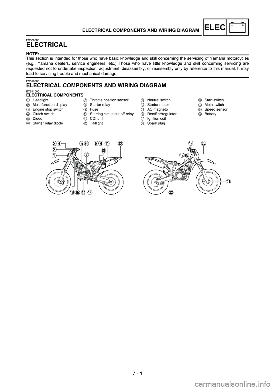
EC611000ELECTRICAL COMPONENTS
1Headlight
2Multi-function display
3Engine stop switch
4Clutch switch
5Diode
6Starter relay diode7Throttle position sensor
8Starter relay
9Fuse
0Starting circuit cut-off relay
ACDI unit
BTaillightCNeutral switch
DStarter motor
EAC magneto
FRectifier/regulator
GIgnition coil
HSpark plugIStart switch
JMain switch
KSpeed sensor
LBattery
Page 823 of 912

7 - 2
–+ELEC
PARTIE ELECTRIQUE
N.B.:
Cette section est destinée aux personnes possédant des connaissances et des compétences de base pour l’entretien des motos Yamaha
(par ex.: concessionnaires Yamaha, techniciens d’entretien, etc.). Les personnes non qualifiées ne doivent entreprendre les opérations
d’inspection, de réglage, de démontage ou de remontage que s’ils se réfèrent à ce manuel. Sinon, ils pourraient engendrer des problè-
mes d’entretien et des dommages mécaniques.
COMPOSANTS ELECTRIQUES ET SCHEMA DE CABLAGE
COMPOSANTS ELECTRIQUES
1
Phare
2
Ecran multifonction
3
Coupe-circuit du moteur
4
Contacteur d’embrayage
5
Diode
6
Diode du relais de démarreur7
Capteur de position de
papillon des gaz
8
Relais de démarreur
9
Fusible
0
Relais de coupe-circuit de
démarrage
A
Boîtier CDIB
Feu arrière
C
Contacteur de point mort
D
Démarreur
E
Alternateur avec rotor à
aimantation permanente
F
Redresseur/régulateur
G
Bobine d’allumageH
Bougie
I
Contacteur du démarreur
J
Contacteur à clé
K
Capteur de vitesse
L
Batterie
ELEKTRISCHE ANLAGE
HINWEIS:
Dieser Abschnitt ist für Personen, die über grundlegende Kenntnisse und Fähigkeiten in der Wartung von Yamaha-Motor-
rädern verfügen (z.B.: Yamaha-Händler, Wartungspersonal etc.). Personen mit geringen Kenntnissen und Fähigkeiten
über Wartungsarbeiten wird empfohlen, keine Inspektionen, Einstellungen, Demontagen durchzuführen und Montagen
nur mit Hilfe dieses Handbuchs vorzunehmen. Es könnten sonst Wartungsprobleme und mechanische Schäden auftreten.
ELEKTRISCHE BAUTEILE UND SCHALTPLAN
ELEKTRISCHE BAUTEILE
1Scheinwerfer
2Multifunktionsanzeige
3Motorstoppschalter
4Kupplungsschalter
5Diode
6Starter-Relais-Diode7Drosselklappensensor
8Starter-Relais
9Sicherung
0Anlasssperrelais
AZündbox
BRücklichtCLeerlaufschalter
DStartermotor
ELichtmaschine
FGleichrichter/Regler
GZündspule
HZündkerzeIStarterschalter
JZündschalter
KGeschwindigkeitssensor
LBatterie
IMPIANTO ELETTRICO
NOTA:
Questo paragrafo è rivolto a coloro che possiedono già conoscenze e competenze di base relative alla manutenzione di motocicli
Yamaha (p.es. concessionari Yamaha, tecnici della manutenzione, ecc.). Alle persone con scarse conoscenze e competenze in materia
di manutenzione si consiglia di non eseguire alcun intervento di ispezione, regolazione, smontaggio o rimontaggio facendo esclusiva-
mente riferimento al presente manuale. Ciò potrebbe comportare problemi di manutenzione e danni meccanici.
COMPONENTI ELETTRICI E SCHEMA ELETTRICO
COMPONENTI ELETTRICI
1
Faro
2
Display multifunzione
3
Interruttore di arresto motore
4
Interruttore della frizione
5
Diodo
6
Diodo del relè del motorino
di avviamento7
Sensore posizione farfalla
8
Relè del motorino di
avviamento
9
Fusibile
0
Relè di interruzione del
circuito di avviamento
A
Unità CDI B
Luce posteriore
C
Interruttore folle
D
Motorino d’avviamento
E
Magnete AC
F
Raddrizzatore/regolatore
G
Bobina di accensione
H
Candela d’accensioneI
Interruttore dell’avviamento
J
Interruttore di accensione
K
Sensore velocità
L
Batteria
SISTEMA ELÉCTRICO
NOTA:
Esta sección está dirigida a los usuarios que tienen conocimientos y habilidades básicos referentes al mantenimiento de
motocicletas Yamaha (p.ej., distribuidores Yamaha, ingenieros de mantenimiento, etc.) Recomendamos que los usuarios
con pocos conocimientos y habilidades referentes al mantenimiento no inspeccionen, ajusten, desmonten ni vuelvan a
montar sólo tomando este manual como referencia. Puede provocar problemas de mantenimiento y daños mecánicos.
COMPONENTES Y ESQUEMA ELÉCTRICO
COMPONENTES ELÉCTRICOS
1Faro
2Visor multifunción
3Interruptor de paro del
motor
4Interruptor del embrague
5Diodo
6Diodo del relé de arranque 7Sensor de posición del
acelerador
8Relé de arranque
9Fusible
0Relé de corte del circuito
de arranque
AUnidad CDIBPiloto trasero
CInterruptor de luz de punto
muerto
DMotor de arranque
EMagneto CA
FRectificador/regulador
GBobina de encendidoHBujía
IInterruptor de arranque
JInterruptor principal
KSensor de velocidad
LBatería
COMPOSANTS ELECTRIQUES ET SCHEMA DE CABLAGE
ELEKTRISCHE BAUTEILE UND SCHALTPLAN
COMPONENTI ELETTRICI E SCHEMA ELETTRICO
COMPONENTES Y ESQUEMA ELÉCTRICO
1
2
3
4
5
6
7