check engine YAMAHA WR 250F 2007 Owner's Guide
[x] Cancel search | Manufacturer: YAMAHA, Model Year: 2007, Model line: WR 250F, Model: YAMAHA WR 250F 2007Pages: 912, PDF Size: 23.95 MB
Page 826 of 912

7 - 5
–+ELECIGNITION SYSTEM
EC620000
IGNITION SYSTEM
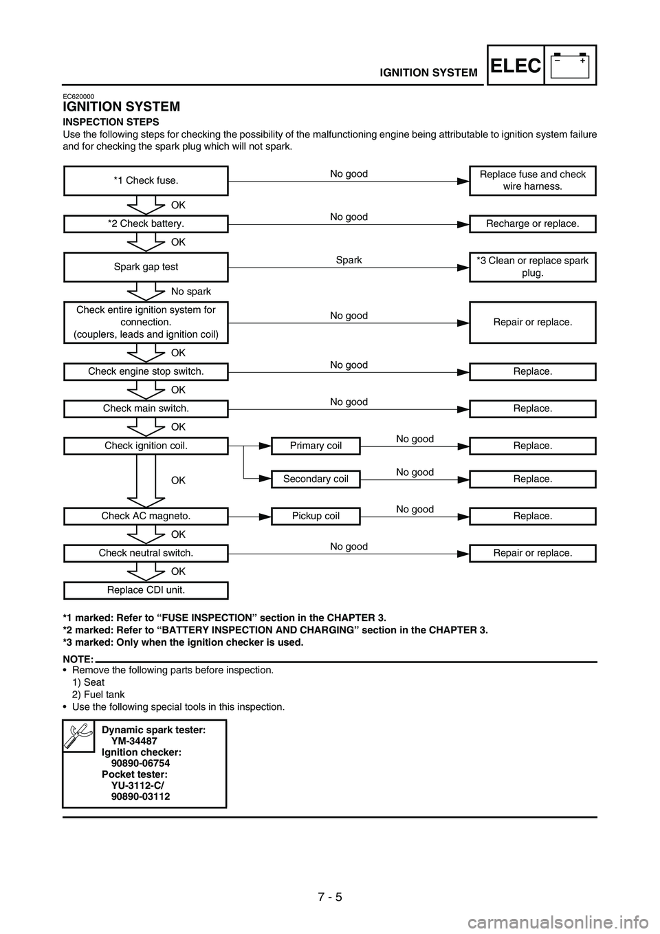
INSPECTION STEPS
Use the following steps for checking the possibility of the malfunctioning engine being attributable to ignition system failure
and for checking the spark plug which will not spark.
*1 marked: Refer to “FUSE INSPECTION” section in the CHAPTER 3.
*2 marked: Refer to “BATTERY INSPECTION AND CHARGING” section in the CHAPTER 3.
*3 marked: Only when the ignition checker is used.
NOTE:•Remove the following parts before inspection.
1) Seat
2) Fuel tank
•Use the following special tools in this inspection.
*1 Check fuse.Replace fuse and check
wire harness.
*2 Check battery. Recharge or replace.
Spark gap test*3 Clean or replace spark
plug.
Check entire ignition system for
connection.
(couplers, leads and ignition coil)Repair or replace.
Check engine stop switch. Replace.
Check main switch.Replace.
Check ignition coil. Primary coil Replace.
Secondary coil Replace.
Check AC magneto. Pickup coil Replace.
Check neutral switch. Repair or replace.
Replace CDI unit.
Dynamic spark tester:
YM-34487
Ignition checker:
90890-06754
Pocket tester:
YU-3112-C/
90890-03112
No good
OK
No good
OK
Spark
No spark
No good
OK
No good
OK
No good
OK
No good
OKNo good
No good
OK
No good
OK
Page 832 of 912

7 - 11
–+ELECIGNITION SYSTEM
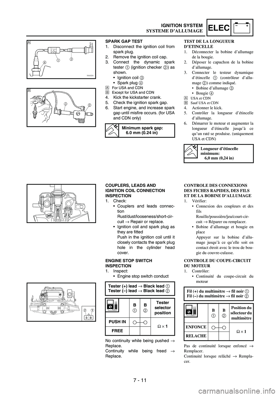
SPARK GAP TEST
1. Disconnect the ignition coil from
spark plug.
2. Remove the ignition coil cap.
3. Connect the dynamic spark
tester
1 (ignition checker
2) as
shown.
•Ignition coil
3
•Spark plug
4
ÈFor USA and CDN
ÉExcept for USA and CDN
4. Kick the kickstarter crank.
5. Check the ignition spark gap.
6. Start engine, and increase spark
gap until misfire occurs. (for USA
and CDN only)
Minimum spark gap:
6.0 mm (0.24 in)
È
É
COUPLERS, LEADS AND
IGNITION COIL CONNECTION
INSPECTION
1. Check:
•Couplers and leads connec-
tion
Rust/dust/looseness/short-cir-
cuit
→ Repair or replace.
•Ignition coil and spark plug as
they are fitted
Push in the ignition coil until it
closely contacts the spark plug
hole in the cylinder head
cover.
ENGINE STOP SWITCH
INSPECTION
1. Inspect:
•Engine stop switch conduct
No continuity while being pushed
→
Replace.
Continuity while being freed
→
Replace.Tester (+) lead →
Black lead 1
Tester (–) lead →
Black lead 2
B
1
B
2
Tester
selector
position
PUSH IN
Ω
×
1
FREE
TEST DE LA LONGUEUR
D’ETINCELLE
1. Déconnecter la bobine d’allumage
de la bougie.
2. Déposer le capuchon de la bobine
d’allumage.
3. Connecter le testeur dynamique
d’étincelle 1 (contrôleur d’allu-
mage 2) comme indiqué.
Bobine d’allumage 3
Bougie 4
È
USA et CDN
É
Sauf USA et CDN
4. Actionner le kick.
5. Contrôler la longueur d’étincelle
d’allumage.
6. Démarrer le moteur et augmenter la
longueur d’étincelle jusqu’à ce
qu’un raté se produise. (uniquement
USA et CDN)
Longueur d’étincelle
minimum:
6,0 mm (0,24 in)
CONTROLE DES CONNEXIONS
DES FICHES RAPIDES, DES FILS
ET DE LA BOBINE D’ALLUMAGE
1. Vérifier:
Connexion des coupleurs et des
fils
Rouille/poussière/jeu/court-cir-
cuit → Réparer ou remplacer.
Bobine d’allumage et bougie en
place
Appuyer sur la bobine d’allu-
mage jusqu’à ce qu’elle soit en
contact étroit avec le trou de bou-
gie du couvre-culasse.
CONTROLE DU COUPE-CIRCUIT
DU MOTEUR
1. Contrôler:
Continuité du coupe-circuit du
moteur
Pas de continuité lorsque enfoncé →
Remplacer.
Continuité lorsque relâché → Rempla-
cer.Fil (+) du multimètre → fil noir 1
Fil (–) du multimètre → fil noir 2
B
1 B
2 Position du
sélecteur du
multimètre
ENFONCE
Ω × 1
RELACHE
SYSTEME D’ALLUMAGE
Page 870 of 912

7 - 49
–+ELECCHARGING SYSTEM
EC624000COUPLERS AND LEADS
CONNECTION INSPECTION
1. Check:
•Couplers and leads connec-
tion
Rust/dust/looseness/short-cir-
cuit
→ Repair or replace.
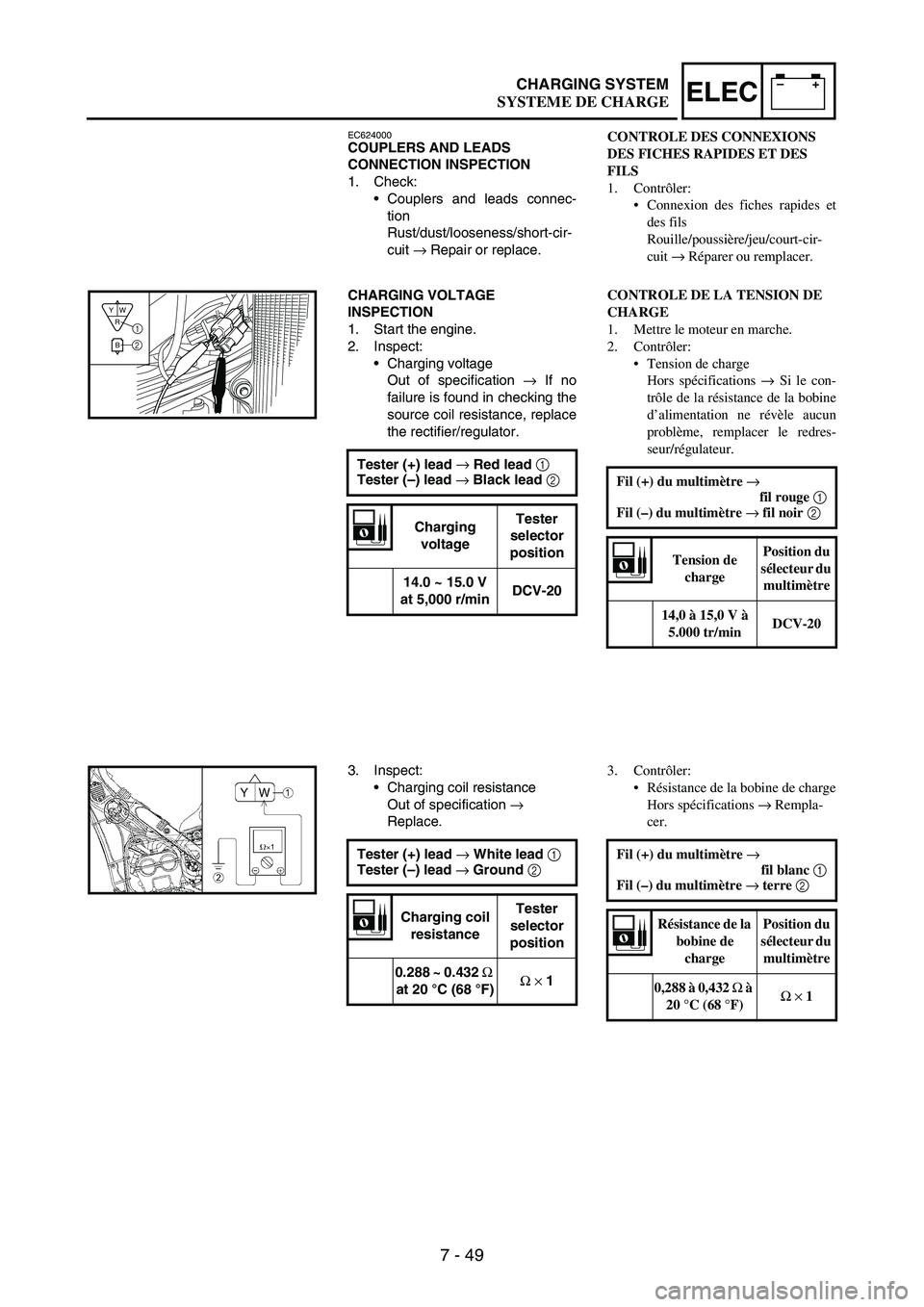
CHARGING VOLTAGE
INSPECTION
1. Start the engine.
2. Inspect:
•Charging voltage
Out of specification
→ If no
failure is found in checking the
source coil resistance, replace
the rectifier/regulator.
Tester (+) lead →
Red lead 1
Tester (–) lead →
Black lead 2
Charging
voltageTester
selector
position
14.0 ~ 15.0 V
at 5,000 r/minDCV-20
R
BW Y1
2
3. Inspect:
•Charging coil resistance
Out of specification
→
Replace.
Tester (+) lead →
White lead 1
Tester (–) lead →
Ground 2
Charging coil
resistanceTester
selector
position
0.288 ~ 0.432 Ω
at 20 °C (68 °F)Ω
×
1
CONTROLE DES CONNEXIONS
DES FICHES RAPIDES ET DES
FILS
1. Contrôler:
Connexion des fiches rapides et
des fils
Rouille/poussière/jeu/court-cir-
cuit → Réparer ou remplacer.
CONTROLE DE LA TENSION DE
CHARGE
1. Mettre le moteur en marche.
2. Contrôler:
Tension de charge
Hors spécifications → Si le con-
trôle de la résistance de la bobine
d’alimentation ne révèle aucun
problème, remplacer le redres-
seur/régulateur.
Fil (+) du multimètre →
fil rouge 1
Fil (–) du multimètre → fil noir 2
Tension de
chargePosition du
sélecteur du
multimètre
14,0 à 15,0 V à
5.000 tr/minDCV-20
3. Contrôler:
Résistance de la bobine de charge
Hors spécifications → Rempla-
cer.
Fil (+) du multimètre →
fil blanc 1
Fil (–) du multimètre → terre 2
Résistance de la
bobine de
chargePosition du
sélecteur du
multimètre
0,288 à 0,432 Ω à
20 °C (68 °F)Ω × 1
SYSTEME DE CHARGE
Page 878 of 912

7 - 57
–+ELECTHROTTLE POSITION SENSOR SYSTEM
HANDLING NOTE
CAUTION:
Do not loosen the screw (throttle
position sensor) 1
except when
changing the throttle position sen-
sor due to failure because it will
cause a drop in engine perfor-
mance.
1
EC624000COUPLERS AND LEADS
CONNECTION INSPECTION
1. Check:
•Couplers and leads connec-
tion
Rust/dust/looseness/short-cir-
cuit
→ Repair or replace.
THROTTLE POSITION SENSOR
COIL INSPECTION
1. Inspect:
•Throttle position sensor coil
resistance
Out of specification
→
Replace.
Tester (+) lead →
Blue lead 1
Tester (–) lead →
Black lead 2
Throttle
position
sensor coil
resistanceTester
selector
position
4 ~ 6 kΩ at
20 °C (68 °F)kΩ × 1
2. Loosen:
•Throttle stop screw 1
NOTE:Turn out the throttle stop screw until
the throttle shaft is in the full close
position.
REMARQUES CONCERNANT LA
MANIPULATION
ATTENTION:
Ne pas desserrer la vis (capteur de
position de papillon des gaz) 1 sauf
en cas de remplacement du capteur de
position de papillon des gaz en raison
d’une panne, car cela provoquerait
une baisse des performances du
moteur.
CONTROLE DES CONNEXIONS
DES FICHES RAPIDES ET DES
FILS
1. Contrôler:
Connexion des fiches rapides et
des fils
Rouille/poussière/jeu/court-cir-
cuit → Réparer ou remplacer.
CONTROLE DE LA BOBINE DU
CAPTEUR DE POSITION DE
PAPILLON DES GAZ
1. Contrôler:
Résistance de la bobine du cap-
teur de position de papillon des
gaz
Hors spécifications → Rempla-
cer.
Fil (+) du multimètre → fil bleu 1
Fil (–) du multimètre → fil noir 2
Résistance de la
bobine du
capteur de
position de
papillon des gazPosition du
sélecteur du
multimètre
4 à 6 kΩ à 20 °C
(68 °F)kΩ × 1
2. Desserrer:
Vis de butée de papillon des gaz
1
N.B.:
Dévisser la vis de butée de papillon des
gaz jusqu’à ce que l’axe de papillon soit
en position complètement fermée.
SYSTEME DU CAPTEUR DE POSITION DE PAPILLON DES GAZ