battery YAMAHA WR 250F 2010 Owners Manual
[x] Cancel search | Manufacturer: YAMAHA, Model Year: 2010, Model line: WR 250F, Model: YAMAHA WR 250F 2010Pages: 232, PDF Size: 13.94 MB
Page 14 of 232
1-4
LOCATION OF IMPORTANT LABELS
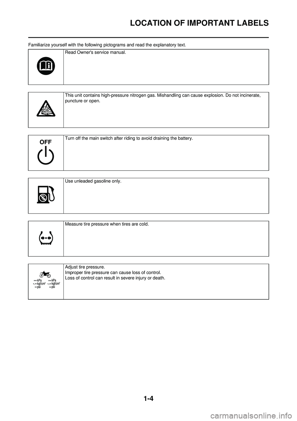
Familiarize yourself with the following pictograms and read the explanatory text.
Read Owner's service manual.
This unit contains high-pressure nitrogen gas. Mishandling can cause explosion. Do not incinerate,
puncture or open.
Turn off the main switch after riding to avoid draining the battery.
Use unleaded gasoline only.
Measure tire pressure when tires are cold.
Adjust tire pressure.
Improper tire pressure ca n cause loss of control.
Loss of control can result in severe injury or death.
Page 22 of 232
1-12
CONTROL FUNCTIONS
CONTROL FUNCTIONS
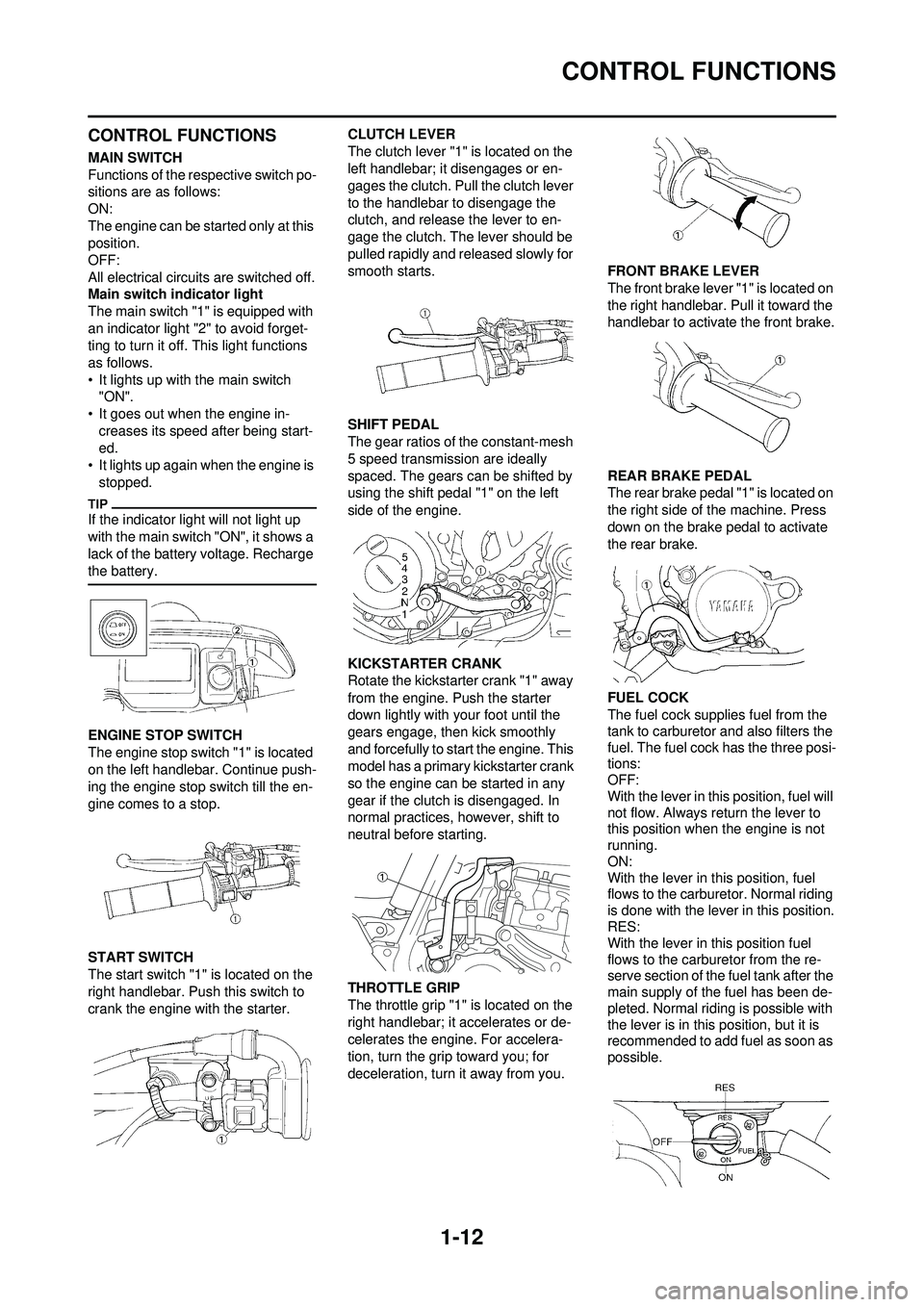
MAIN SWITCH
Functions of the respective switch po-
sitions are as follows:
ON:
The engine can be started only at this
position.
OFF:
All electrical circuits are switched off.
Main switch indicator light
The main switch "1" is equipped with
an indicator light "2" to avoid forget-
ting to turn it off. This light functions
as follows.
• It lights up with the main switch "ON".
• It goes out when the engine in-
creases its speed after being start-
ed.
• It lights up again when the engine is
stopped.
If the indicator light will not light up
with the main switch "ON", it shows a
lack of the battery voltage. Recharge
the battery.
ENGINE STOP SWITCH
The engine stop switch "1" is located
on the left handlebar. Continue push-
ing the engine stop switch till the en-
gine comes to a stop.
START SWITCH
The start switch "1" is located on the
right handlebar. Push this switch to
crank the engine with the starter. CLUTCH LEVER
The clutch lever "1" is located on the
left handlebar; it disengages or en-
gages the clutch. Pull the clutch lever
to the handlebar to disengage the
clutch, and release the lever to en-
gage the clutch. The lever should be
pulled rapidly and released slowly for
smooth starts.
SHIFT PEDAL
The gear ratios of the constant-mesh
5 speed transmission are ideally
spaced. The gears can be shifted by
using the shift pedal "1" on the left
side of the engine.
KICKSTARTER CRANK
Rotate the kickstarter crank "1" away
from the engine. Push the starter
down lightly with your foot until the
gears engage, then kick smoothly
and forcefully to start the engine. This
model has a primary kickstarter crank
so the engine can be started in any
gear if the clutch is disengaged. In
normal practices, however, shift to
neutral before starting.
THROTTLE GRIP
The throttle grip "1" is located on the
right handlebar; it accelerates or de-
celerates the engine. For accelera-
tion, turn the grip
toward you; for
deceleration, turn it away from you. FRONT BRAKE LEVER
The front brake lever "1" is located on
the right handlebar. Pull it toward the
handlebar to activate the front brake.
REAR BRAKE PEDAL
The rear brake pedal "1" is located on
the right side of the machine. Press
down on the brake pedal to activate
the rear brake.
FUEL COCK
The fuel cock supplies fuel from the
tank to carburetor and also filters the
fuel. The fuel cock has the three posi-
tions:
OFF:
With the lever in this position, fuel will
not flow. Always return the lever to
this position when the engine is not
running.
ON:
With the lever in this position, fuel
flows to the carburetor. Normal riding
is done with the lever in this position.
RES:
With the lever in this position fuel
flows to the carburetor from the re-
serve section of the fuel tank after the
main supply of the fuel has been de-
pleted. Normal riding is possible with
the lever is in this position, but it is
recommended to add fuel as soon as
possible.
Page 28 of 232
1-18
STARTING AND BREAK-IN
STARTING AND BREAK-IN
FUEL
Always use the recommended fuel as
stated below. Also, be sure to use
new gasoline.
Use only unleaded gasoline. The
use of leaded gasoline will cause
severe damage to the engine inter-
nal parts such as valves, piston
rings, and exhaust system, etc.
If knocking or pinging occurs, use a
different brand of gasoline or higher
octane grade.
• For refueling, be sure to stop the
engine and use enough care not
to spill any fuel. Also be sure to
avoid refueling close to a fire.
• Refuel after the engine, exhaust pipe, etc. have cooled off.
Gasohol (For Canada)
There are two types of gasohol: gas-
ohol containing ethanol and that con-
taining methanol. Gasohol containing
ethanol can be used if the ethanol
content does not exceed 10%. Gaso-
hol containing methanol is not recom-
mended by Yamaha because it can
cause damage to the fuel system or
vehicle performance problems.
HANDLING NOTE
Never start or run the engine in a
closed area. The exhaust fumes
are poisonous; they can cause
loss of consciousness and death
in a very short time. Always oper-
ate the machine in a well-ventilated
area.
• The carburetor on this machine has a built-in accelerator pump.
Therefore, when starting the en-
gine, do not operate the throttle
or the spark plug will foul.
• Unlike a two-stroke engine, this engine cannot be kick started
when the throttl e is open be-
cause the kickstarter may kick
back. Also, if the throttle is open
the air/fuel mixture may be too
lean for the engine to start.
• Before starting the machine, per- form the checks in the pre-opera-
tion check list.
AIR FILTER MAINTENANCE
According to "CLEANING THE AIR
FILTER ELEMENT" section in the
CHAPTER 3, apply the foam-air-filter
oil or its equivalent to the element.
(Excess oil in the element may ad-
versely affect engine starting.)
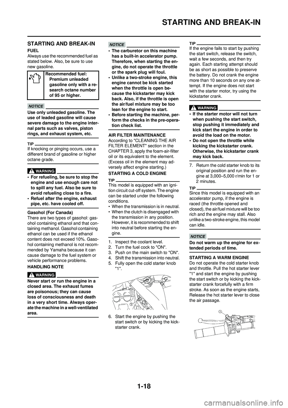
STARTING A COLD ENGINE
This model is equipped with an igni-
tion circuit cut-off system. The engine
can be started under the following
conditions.
• When the transmission is in neutral.
• When the clutch is disengaged with
the transmission in any position.
However, it is recommended to shift
into neutral before starting the en-
gine.
1. Inspect the coolant level.
2. Turn the fuel cock to "ON".
3. Push on the main switch to "ON".
4. Shift the transmission into neutral.
5. Fully open the cold starter knob "1".
6. Start the engine by pushing the start switch or by kicking the kick-
starter crank.
If the engine fails to start by pushing
the start switch, re lease the switch,
wait a few seconds, and then try
again. Each starting attempt should
be as short as possible to preserve
the battery. Do not crank the engine
more than 10 seconds on any one at-
tempt. If the engine does not start
with the starter motor, try using the
kickstarter crank.
• If the starter motor will no t turn
when pushing the start switch,
stop pushing it immediately and
kick start the engine in order to
avoid the load on the motor.
• Do not open the throttle while kicking the kickstarter crank.
Otherwise, the kickstarter crank
may kick back.
7. Return the cold starter knob to its original position and run the en-
gine at 3,000–5,000 r/min for 1 or
2 minutes.
Since this model is equipped with an
accelerator pump, if the engine is
raced (the throttle opened and
closed), the air/fuel mixture will be too
rich and the engine may stall. Also
unlike a two-stroke engine, this model
can idle.
Do not warm up th e engine for ex-
tended periods of time.
STARTING A WARM ENGINE
Do not operate the cold starter knob
and throttle. Pull the hot starter lever
"1" and start the engine by pushing
the start switch or by kicking the kick-
starter crank forcefully with a firm
stroke. As soon as the engine starts,
Release the hot starter lever to close
the air passage.
Recommended fuel:
Premium unleaded
gasoline only with a re-
search octane number
of 95 or higher.
Page 34 of 232
2-3
MAINTENANCE SPECIFICATIONS
MAINTENANCE SPECIFICATIONS
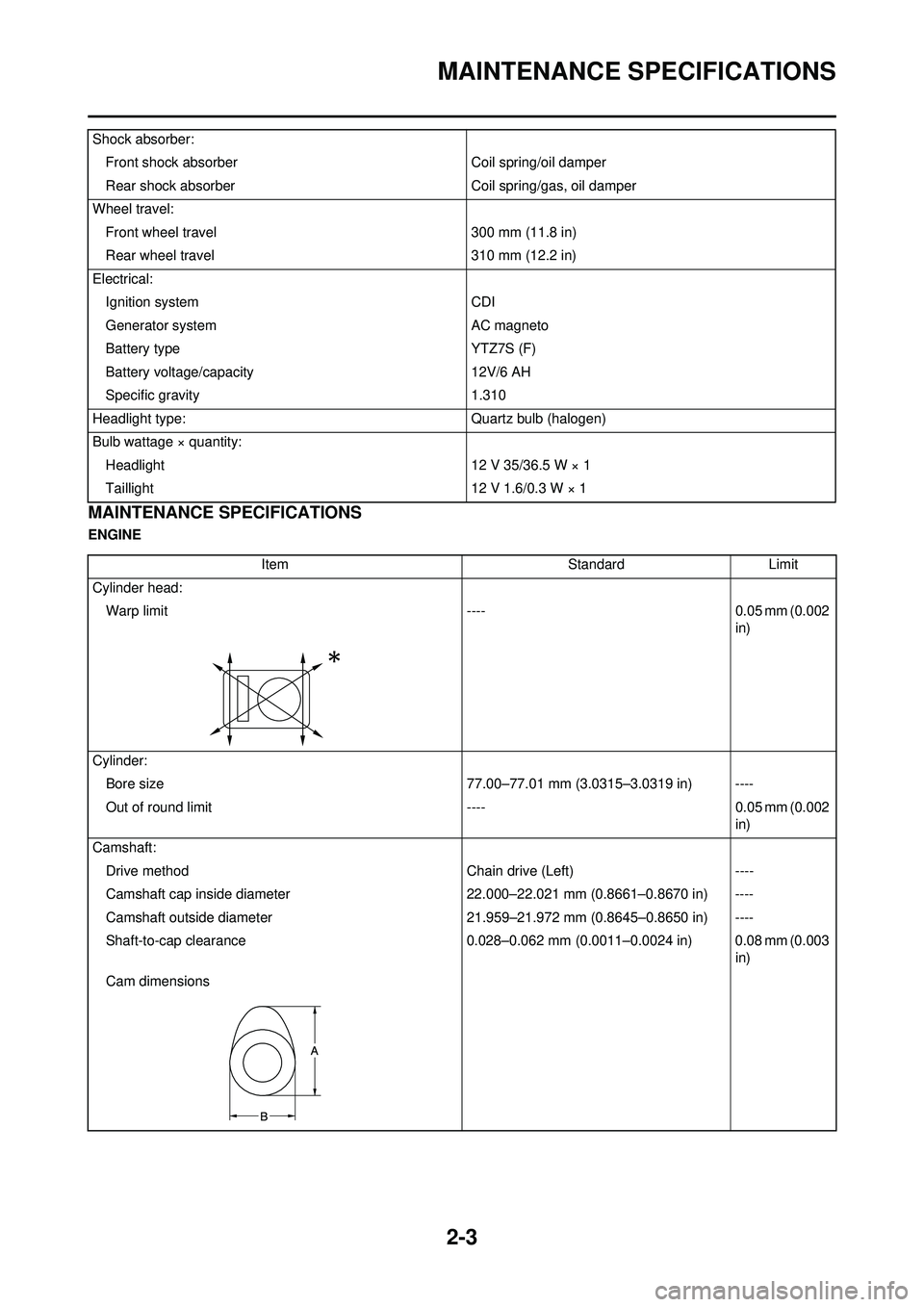
ENGINEShock absorber:
Front shock absorber Coil spring/oil damper
Rear shock absorber Coil spring/gas, oil damper
Wheel travel: Front wheel travel 300 mm (11.8 in)
Rear wheel travel 310 mm (12.2 in)
Electrical: Ignition system CDI
Generator system AC magneto
Battery type YTZ7S (F)
Battery voltage/capacity 12V/6 AH
Specific gravity 1.310
Headlight type: Quartz bulb (halogen)
Bulb wattage × quantity: Headlight 12 V 35/36.5 W × 1
Taillight 12 V 1.6/0.3 W × 1
ItemStandardLimit
Cylinder head: Warp limit ----0.05 mm (0.002
in)
Cylinder: Bore size 77.00–77.01 mm (3.0315–3.0319 in) ----
Out of round limit ----0.05 mm (0.002
in)
Camshaft: Drive method Chain drive (Left)----
Camshaft cap inside diameter 22.000–22.021 mm (0.8661–0.8670 in) ----
Camshaft outside diameter 21.959–21.972 mm (0.8645–0.8650 in) ----
Shaft-to-cap clearance 0.028–0.062 mm (0.0011–0.0024 in) 0.08 mm (0.003
in)
Cam dimensions
Page 52 of 232
2-21
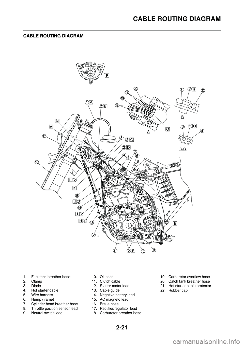
CABLE ROUTING DIAGRAM
CABLE ROUTING DIAGRAM
1. Fuel tank breather hose
2. Clamp
3. Diode
4. Hot starter cable
5. Wire harness
6. Hump (frame)
7. Cylinder head breather hose
8. Throttle position sensor lead
9. Neutral switch lead10. Oil hose
11. Clutch cable
12. Starter motor lead
13. Cable guide
14. Negative battery lead
15. AC magneto lead
16. Brake hose
17. Rectifier/regulator lead
18. Carburetor breather hose 19. Carburetor overflow hose
20. Catch tank breather hose
21. Hot starter cable protector
22. Rubber cap
Page 53 of 232
2-22
CABLE ROUTING DIAGRAM
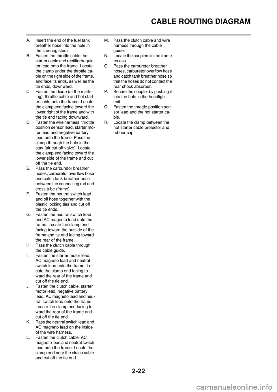
A. Insert the end of the fuel tank breather hose into the hole in
the steering stem.
B. Fasten the throttle cable, hot
starter cable and rectifier/regula-
tor lead onto the frame. Locate
the clamp under the throttle ca-
ble on the right side of the frame,
and face its ends, as well as the
tie ends, downward.
C. Fasten the diode (at the mark- ing), throttle cable and hot start-
er cable onto the frame. Locate
the clamp end facing toward the
lower right of the frame and with
the tie end facing downward.
D. Fasten the wire harness, throttle position sensor lead, starter mo-
tor lead and negative battery
lead onto the frame. Pass the
clamp through the hole in the
stay (air cut-off valve). Locate
the clamp end facing toward the
lower side of the frame and cut
off the tie end.
E. Pass the carburetor breather hoses, carburetor overflow hose
and catch tank breather hose
between the connecting rod and
cross tube (frame).
F. Fasten the neutral switch lead
and oil hose together with the
plastic locking ties and cut off
the tie ends.
G. Fasten the neutral switch lead and AC magneto lead onto the
frame. Locate the clamp end
facing toward the outside of the
frame and tie end facing toward
the rear of the frame.
H. Pass the clutch cable through the cable guide.
I. Fasten the starter motor lead, AC magneto lead and neutral
switch lead onto the frame. Lo-
cate the clamp end facing to-
ward the rear of the frame and
cut off the tie end.
J. Fasten the clutch cable, starter motor lead, negative battery
lead, AC magneto lead and neu-
tral switch lead onto the frame.
Locate the clamp end facing to-
ward the rear of the frame and
cut off the tie end.
K. Pass the neutral switch lead and AC magneto lead on the inside
of the wire harness.
L. Fasten the clutch cable, AC magneto lead and neutral switch
lead onto the frame. Locate the
clamp end near the clutch cable
and cut off the tie end. M. Pass the clutch cable and wire
harness through the cable
guide.
N. Locate the couplers in the frame
recess.
O. Pass the carburetor breather hoses, carburetor overflow hose
and catch tank breather hose so
that the hoses do not contact the
rear shock absorber.
P. Secure the coupler by pushing it into the hole in the headlight
unit.
Q. Fasten the throttle position sen- sor lead and the hot starter ca-
ble.
R. Locate the clamp between the hot starter cable protector and
rubber cap.
Page 56 of 232
2-25
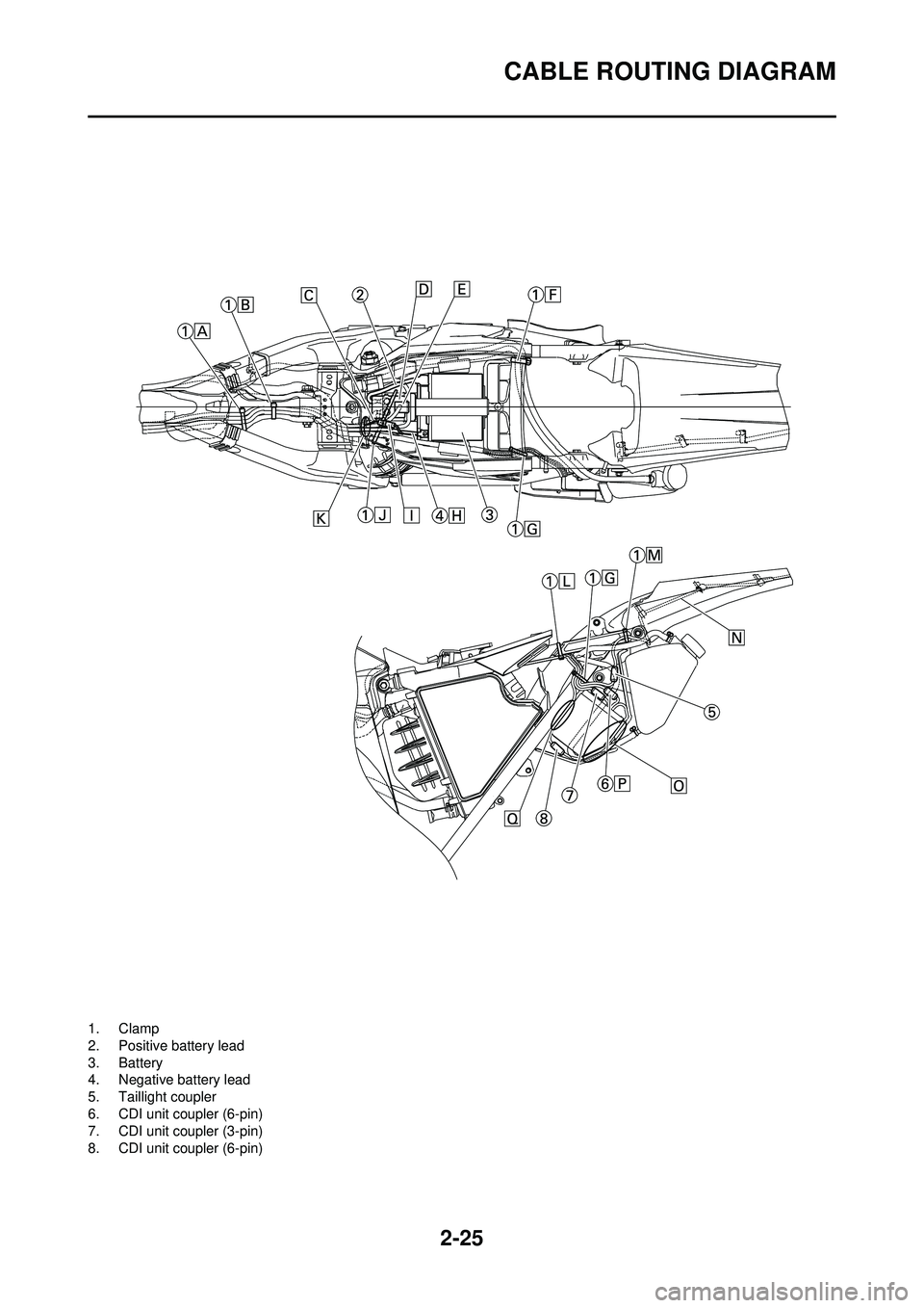
CABLE ROUTING DIAGRAM
1. Clamp
2. Positive battery lead
3. Battery
4. Negative battery lead
5. Taillight coupler
6. CDI unit coupler (6-pin)
7. CDI unit coupler (3-pin)
8. CDI unit coupler (6-pin)
Page 57 of 232
2-26
CABLE ROUTING DIAGRAM
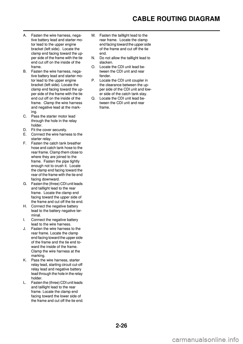
A. Fasten the wire harness, nega-tive battery lead and starter mo-
tor lead to the upper engine
bracket (left side) . Locate the
clamp end facing toward the up-
per side of the frame with the tie
end cut off on the inside of the
frame.
B. Fasten the wire harness, nega- tive battery lead and starter mo-
tor lead to the upper engine
bracket (left side). Locate the
clamp end facing toward the up-
per side of the frame with the tie
end cut off on the inside of the
frame. Clamp the wire harness
and negative lead at the mark-
ing.
C. Pass the starter motor lead
through the hole in the relay
holder.
D. Fit the cover securely.
E. Connect the wire harness to the starter relay.
F. Fasten the catch tank breather
hose and catch tank hose to the
rear frame. Clamp them close to
where they are joined to the
frame. Fasten the pipe tightly
enough not to crush it. Locate
the clamp end facing toward the
rear of the frame with the tie end
facing downward.
G. Fasten the (three) CDI unit leads
and taillight lead to the rear
frame. Locate the clamp end
facing toward the upper side of
the frame and cut off the tie end.
H. Connect the negative battery
lead to the battery negative ter-
minal.
I. Connect the negative battery
lead to the wire harness.
J. Fasten the wire harness to the rear frame. Locate the clamp
end facing toward the upper side
of the frame and the tie end to-
ward the inside of the frame.
Clamp the wire harness at the
marking.
K. Pass the wire harness, starter
relay lead, starting circuit cut-off
relay lead and negative battery
lead through the hole in the relay
holder.
L. Fasten the (three) CDI unit leads and taillight lead to the rear
frame. Locate the clamp end
facing toward the lower side of
the frame and cut off the tie end. M. Fasten the taillight lead to the
rear frame. Locate the clamp
end facing toward the upper side
of the frame and cut off the tie
end.
N. Do not allow the taillight lead to slacken.
O. Locate the CDI unit lead be- tween the CDI unit and rear
fender.
P. Locate the CDI unit coupler in the clearance between the up-
per side of the CDI unit and low-
er side of the catch tank stay.
Q. Locate the CDI unit lead be- tween the CDI unit and rear
frame.
Page 62 of 232
3-3
MAINTENANCE INTERVALS FOR COMPETITION USE
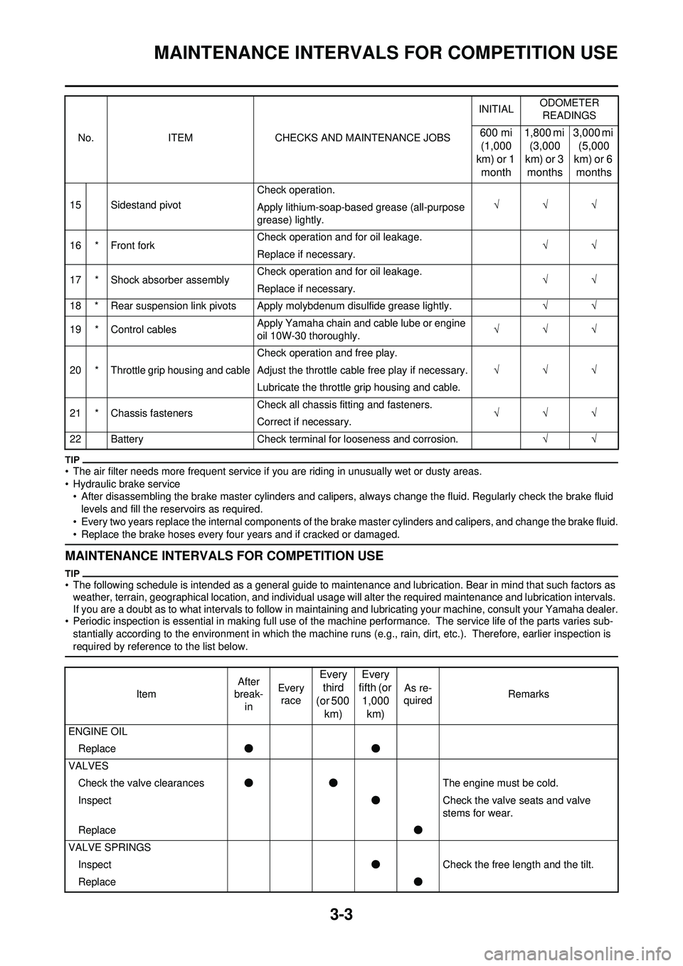
• The air filter needs more frequent service if you are riding in unusually wet or dusty areas.
• Hydraulic brake service • After disassembling the brake master cylinders and calipers, always change the fluid. Regularly check the brake fluid
levels and fill the reservoirs as required.
• Every two years replace the internal components of the brake master cylinders and calipers, and change the brake fluid.
• Replace the brake hoses every four years and if cracked or damaged.
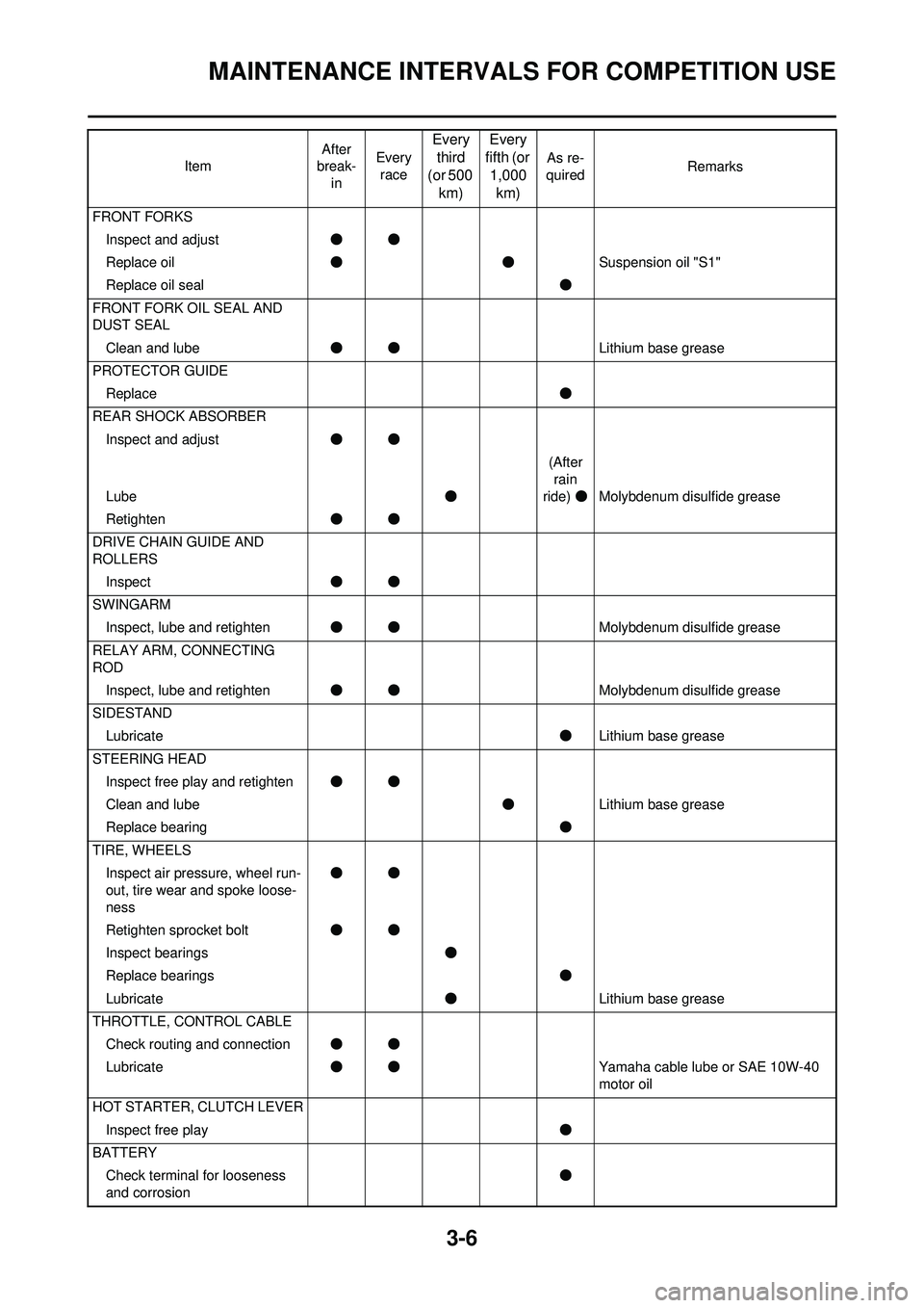
MAINTENANCE INTERVALS FOR COMPETITION USE
• The following schedule is intended as a general guide to mainten ance and lubrication. Bear in mind that such factors as
weather, terrain, geographical location, and individual usage will alter the required maintenance and lubrication intervals.
If you are a doubt as to what intervals to follow in mainta ining and lubricating your machine, consult your Yamaha dealer.
• Periodic inspection is essential in making full use of the ma chine performance. The service life of the parts varies sub-
stantially according to the environment in which the machine runs (e.g., rain, dirt, etc.). Therefore, earlier inspection is
required by reference to the list below.
15 Sidestand pivot Check operation.
√√√
Apply lithium-soap-bas ed grease (all-purpose
grease) lightly.
16 * Front fork Check operation and for oil leakage.
√√
Replace if necessary.
17 * Shock absorber assembly Check operation and for oil leakage.
√√
Replace if necessary.
18 * Rear suspension link pivots Apply molybdenum disulfide grease lightly. √√
19 * Control cables Apply Yamaha chain and cable lube or engine
oil 10W-30 thoroughly. √√√
20 * Throttle grip housing and cable Check operation and free play.
√√√
Adjust the throttle cable free play if necessary.
Lubricate the throttle grip housing and cable.
21 * Chassis fasteners Check all chassis fitting and fasteners.
√√√
Correct if necessary.
22 Battery Check terminal for looseness and corrosion. √√
No. ITEM CHECKS AND MAINTENANCE JOBS
INITIAL
ODOMETER
READINGS
600 mi (1,000
km) or 1
month 1,800 mi
(3,000
km) or 3
months 3,000 mi
(5,000
km) or 6
months
Item After
break-
in Every
race
Every third
(or 500
km) Every
fifth (or 1,000
km)
As re-
quired Remarks
ENGINE OIL Replace ●●
VALVES Check the valve clearances ●● The engine must be cold.
Inspect ●Check the valve seats and valve
stems for wear.
Replace ●
VALVE SPRINGS Inspect ●Check the free length and the tilt.
Replace ●
Page 65 of 232
3-6
MAINTENANCE INTERVALS FOR COMPETITION USE
FRONT FORKSInspect and adjust ●●
Replace oil ●● Suspension oil "S1"
Replace oil seal ●
FRONT FORK OIL SEAL AND
DUST SEAL Clean and lube ●● Lithium base grease
PROTECTOR GUIDE Replace ●
REAR SHOCK ABSORBER Inspect and adjust ●●
Lube ●(After
rain
ride) ●Molybdenum disulfide grease
Retighten ●●
DRIVE CHAIN GUIDE AND
ROLLERS Inspect ●●
SWINGARM Inspect, lube and retighten ●● Molybdenum disulfide grease
RELAY ARM, CONNECTING
ROD Inspect, lube and retighten ●● Molybdenum disulfide grease
SIDESTAND Lubricate ●Lithium base grease
STEERING HEAD Inspect free play and retighten ●●
Clean and lube ●Lithium base grease
Replace bearing ●
TIRE, WHEELS Inspect air pressure, wheel run-
out, tire wear and spoke loose-
ness ●●
Retighten sprocket bolt ●●
Inspect bearings ●
Replace bearings ●
Lubricate ●Lithium base grease
THROTTLE, CONTROL CABLE Check routing and connection ●●
Lubricate ●● Yamaha cable lube or SAE 10W-40
motor oil
HOT STARTER, CLUTCH LEVER Inspect free play ●
BATTERY Check terminal for looseness
and corrosion ●
Item
After
break- in Every
race
Every third
(or 500 km) Every
fifth (or
1,000 km)
As re-
quired Remarks