wheel YAMAHA WR 250F 2014 User Guide
[x] Cancel search | Manufacturer: YAMAHA, Model Year: 2014, Model line: WR 250F, Model: YAMAHA WR 250F 2014Pages: 230, PDF Size: 13.01 MB
Page 46 of 230
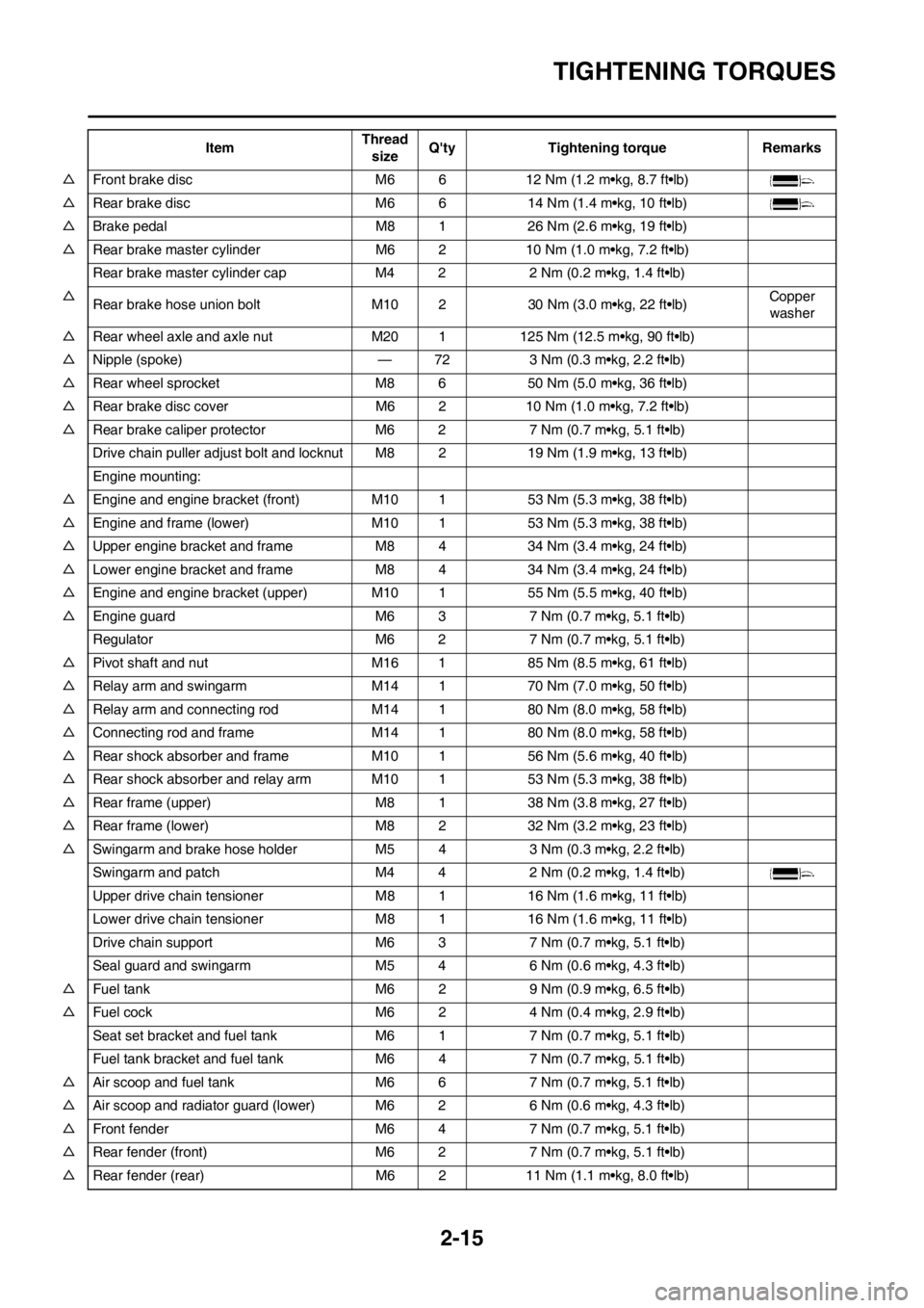
2-15
TIGHTENING TORQUES
△Front brake disc M6 6 12 Nm (1.2 m•kg, 8.7 ft•lb)
△Rear brake disc M6 6 14 Nm (1.4 m•kg, 10 ft•lb)
△Brake pedal M8 1 26 Nm (2.6 m•kg, 19 ft•lb)
△Rear brake master cylinder M6 2 10 Nm (1.0 m•kg, 7.2 ft•lb)
Rear brake master cylinder cap M4 2 2 Nm (0.2 m•kg, 1.4 ft•lb)
△
Rear brake hose union bolt M10 2 30 Nm (3.0 m•kg, 22 ft•lb)Copper
washer
△Rear wheel axle and axle nut M20 1 125 Nm (12.5 m•kg, 90 ft•lb)
△Nipple (spoke) — 72 3 Nm (0.3 m•kg, 2.2 ft•lb)
△Rear wheel sprocket M8 6 50 Nm (5.0 m•kg, 36 ft•lb)
△Rear brake disc cover M6 2 10 Nm (1.0 m•kg, 7.2 ft•lb)
△Rear brake caliper protector M6 2 7 Nm (0.7 m•kg, 5.1 ft•lb)
Drive chain puller adjust bolt and locknut M8 2 19 Nm (1.9 m•kg, 13 ft•lb)
Engine mounting:
△Engine and engine bracket (front) M10 1 53 Nm (5.3 m•kg, 38 ft•lb)
△Engine and frame (lower) M10 1 53 Nm (5.3 m•kg, 38 ft•lb)
△Upper engine bracket and frame M8 4 34 Nm (3.4 m•kg, 24 ft•lb)
△Lower engine bracket and frame M8 4 34 Nm (3.4 m•kg, 24 ft•lb)
△Engine and engine bracket (upper) M10 1 55 Nm (5.5 m•kg, 40 ft•lb)
△Engine guard M6 3 7 Nm (0.7 m•kg, 5.1 ft•lb)
Regulator M6 2 7 Nm (0.7 m•kg, 5.1 ft•lb)
△Pivot shaft and nut M16 1 85 Nm (8.5 m•kg, 61 ft•lb)
△Relay arm and swingarm M14 1 70 Nm (7.0 m•kg, 50 ft•lb)
△Relay arm and connecting rod M14 1 80 Nm (8.0 m•kg, 58 ft•lb)
△Connecting rod and frame M14 1 80 Nm (8.0 m•kg, 58 ft•lb)
△Rear shock absorber and frame M10 1 56 Nm (5.6 m•kg, 40 ft•lb)
△Rear shock absorber and relay arm M10 1 53 Nm (5.3 m•kg, 38 ft•lb)
△Rear frame (upper) M8 1 38 Nm (3.8 m•kg, 27 ft•lb)
△Rear frame (lower) M8 2 32 Nm (3.2 m•kg, 23 ft•lb)
△Swingarm and brake hose holder M54 3 Nm (0.3 m•kg, 2.2 ft•lb)
Swingarm and patch M4 4 2 Nm (0.2 m•kg, 1.4 ft•lb)
Upper drive chain tensioner M8 1 16 Nm (1.6 m•kg, 11 ft•lb)
Lower drive chain tensioner M8 1 16 Nm (1.6 m•kg, 11 ft•lb)
Drive chain support M6 3 7 Nm (0.7 m•kg, 5.1 ft•lb)
Seal guard and swingarm M5 4 6 Nm (0.6 m•kg, 4.3 ft•lb)
△Fuel tank M6 2 9 Nm (0.9 m•kg, 6.5 ft•lb)
△Fuel cock M6 2 4 Nm (0.4 m•kg, 2.9 ft•lb)
Seat set bracket and fuel tankM6 1 7 Nm (0.7 m•kg, 5.1 ft•lb)
Fuel tank bracket and fuel tank M6 4 7 Nm (0.7 m•kg, 5.1 ft•lb)
△Air scoop and fuel tank M6 6 7 Nm (0.7 m•kg, 5.1 ft•lb)
△Air scoop and radiator guard (lower) M6 2 6 Nm (0.6 m•kg, 4.3 ft•lb)
△Front fender M6 4 7 Nm (0.7 m•kg, 5.1 ft•lb)
△Rear fender (front) M6 2 7 Nm (0.7 m•kg, 5.1 ft•lb)
△Rear fender (rear) M6 2 11 Nm (1.1 m•kg, 8.0 ft•lb)ItemThread
sizeQ'ty Tightening torque Remarks
Page 63 of 230

3-4
MAINTENANCE INTERVALS FOR COMPETITION USE
STEERING HEAD
Inspect free play and retighten●●
Clean and lube●Lithium base grease
Replace bearing●
TIRE, WHEELS
Inspect air pressure, wheel run-
out, tire wear and spoke loose-
ness●●
Retighten sprocket bolt●●
Inspect bearings●
Replace bearings●
Lubricate●Lithium base grease
THROTTLE, CONTROL CABLE
Check routing and connection●●
Lubricate●●Yamaha cable lube or SAE 10W-40
motor oil
HOT STARTER, CLUTCH LEVER
Inspect free play●
BATTERY
Check terminal for looseness
and corrosion● ItemAfter
break-
inEvery
race
Every
third
(or 500
km)Every
fifth (or
1,000
km)
As re-
quiredRemarks
Page 64 of 230

3-5
PRE-OPERATION INSPECTION AND MAINTENANCE
PRE-OPERATION INSPECTION AND MAINTENANCE
Before riding for break-in operation or practice, make sure the machine is in good operating condition.
Before using this machine, check the following points.
GENERAL INSPECTION AND MAINTENANCE
Item Routine Page
CoolantCheck that coolant is filled up to the radiator cap. Check the cool-
ing system for leakage.P.3-9 – 10
FuelCheck that a fresh gasoline is filled in the fuel tank. Check the fuel
line for leakage.P.1-18
Engine oilCheck that the oil level is correct. Check the crankcase and oil
line for leakage.P.3-12 – 13
Gear shifter and clutchCheck that gears can be shifted correctly in order and that the
clutch operates smoothly.P.3-10 – 11
Throttle grip/HousingCheck that the throttle grip operation and free play are correctly
adjusted. Lubricate the throttle grip and housing, if necessary.P.3-11
Brakes Check the play of front brake and effect of front and rear brake. P.3-17 – 20
Drive chainCheck drive chain slack and alignment. Check that the drive chain
is lubricated properly.P.3-20 – 21
WheelsCheck for excessive wear and tire pressure. Check for loose
spokes and have no excessive play.P.3-24
SteeringCheck that the handlebar can be turned smoothly and have no ex-
cessive play.P.3-24 – 25
Front forks and rear shock
absorberCheck that they operate smoothly and there is no oil leakage.
P.3-21 – 24
Cables (wires)Check that the clutch and throttle cables move smoothly. Check
that they are not caught when the handlebars are turned or when
the front forks travel up and down.—
Exhaust pipe Check that the exhaust pipe is tightly mounted and has no cracks. P.3-8 – 9
Rear wheel sprocket Check that the rear wheel sprocket tightening bolt is not loose. P.3-20
Lubrication Check for smooth operation. Lubricate if necessary. P.3-26
Bolts and nuts Check the chassis and engine for loose bolts and nuts. P.1-20
Lead connectorsCheck that the AC magneto, CDI unit, and ignition coil are con-
nected tightly.P.1-6
SettingsIs the machine set suitably for the condition of the course and
weather or by taking into account the results of test runs before
riding? Are inspection and maintenance completely done?P.4-1 – 10
Page 78 of 230
3-19
CHASSIS
3. Inspect:
• Brake fluid level
Refer to "CHECKING THE
BRAKE FLUID LEVEL" section.
4. Check:
• Brake lever operation
A softy or spongy feeling→Bleed
brake system.
Refer to "BLEEDING THE HY-
DRAULIC BRAKE SYSTEM" sec-
tion.
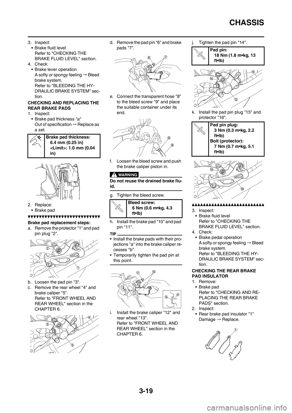
CHECKING AND REPLACING THE
REAR BRAKE PADS
1. Inspect:
• Brake pad thickness "a"
Out of specification→Replace as
a set.
2. Replace:
• Brake pad
Brake pad replacement steps:
a. Remove the protector "1" and pad
pin plug "2".
b. Loosen the pad pin "3".
c. Remove the rear wheel "4" and
brake caliper "5".
Refer to "FRONT WHEEL AND
REAR WHEEL" section in the
CHAPTER 6.d. Remove the pad pin "6" and brake
pads "7".
e. Connect the transparent hose "8"
to the bleed screw "9" and place
the suitable container under its
end.
f. Loosen the bleed screw and push
the brake caliper piston in.
Do not reuse the drained brake flu-
id.
g. Tighten the bleed screw.
h. Install the brake pad "10" and pad
pin "11".
• Install the brake pads with their pro-
jections "a" into the brake caliper re-
cesses "b".
• Temporarily tighten the pad pin at
this point.
i. Install the brake caliper "12" and
rear wheel "13".
Refer to "FRONT WHEEL AND
REAR WHEEL" section in the
CHAPTER 6.j. Tighten the pad pin "14".
k. Install the pad pin plug "15" and
protector "16".
3. Inspect:
• Brake fluid level
Refer to "CHECKING THE
BRAKE FLUID LEVEL" section.
4. Check:
• Brake pedal operation
A softy or spongy feeling→Bleed
brake system.
Refer to "BLEEDING THE HY-
DRAULIC BRAKE SYSTEM" sec-
tion.
CHECKING THE REAR BRAKE
PAD INSULATOR
1. Remove:
• Brake pad
Refer to "CHECKING AND RE-
PLACING THE REAR BRAKE
PADS" section.
2. Inspect:
• Rear brake pad insulator "1"
Damage→Replace. Brake pad thickness:
6.4 mm (0.25 in)
in)
Bleed screw:
6 Nm (0.6 m•kg, 4.3
ft•lb)
Pad pin:
18 Nm (1.8 m•kg, 13
ft•lb)
Pad pin plug:
3 Nm (0.3 m•kg, 2.2
ft•lb)
Bolt (protector):
7 Nm (0.7 m•kg, 5.1
ft•lb)
Page 79 of 230
3-20
CHASSIS
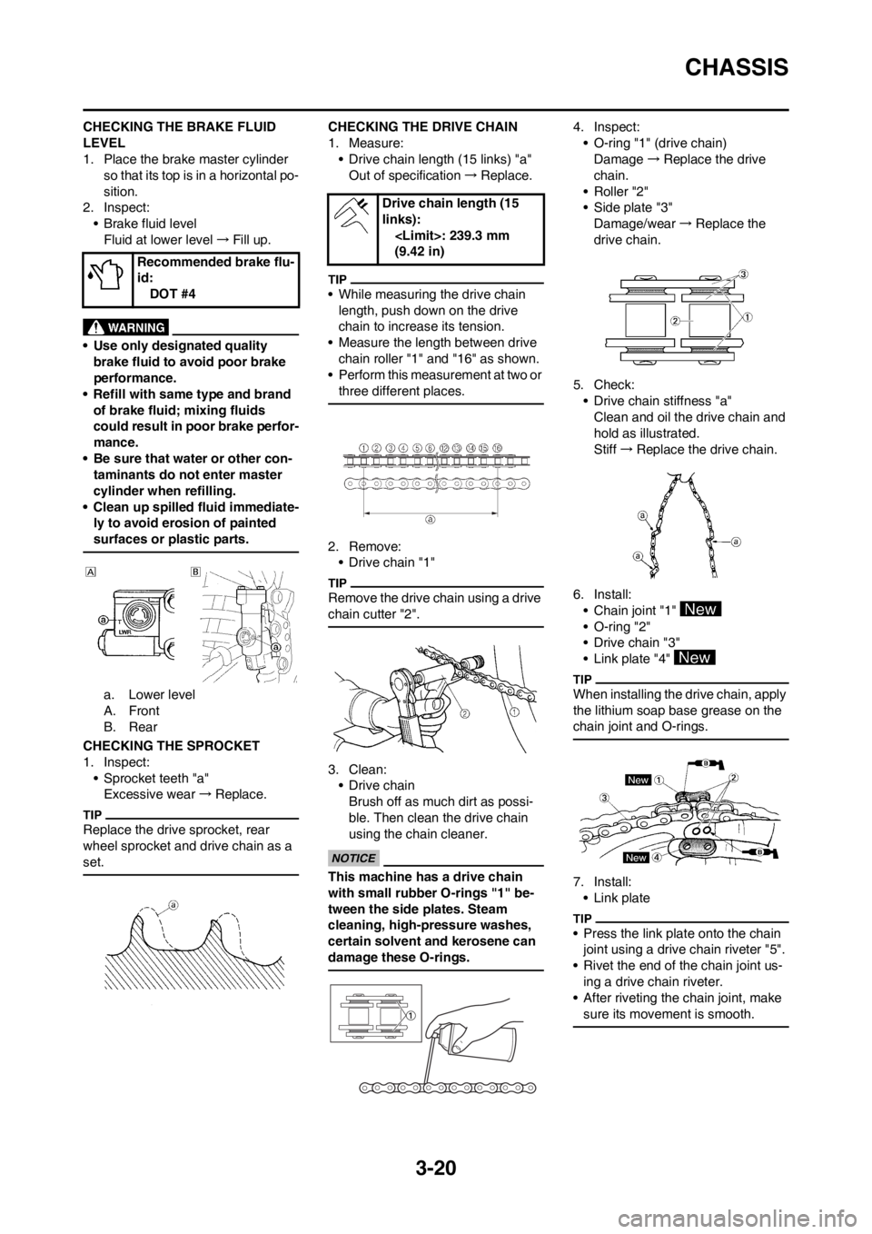
CHECKING THE BRAKE FLUID
LEVEL
1. Place the brake master cylinder
so that its top is in a horizontal po-
sition.
2. Inspect:
• Brake fluid level
Fluid at lower level→Fill up.
• Use only designated quality
brake fluid to avoid poor brake
performance.
• Refill with same type and brand
of brake fluid; mixing fluids
could result in poor brake perfor-
mance.
• Be sure that water or other con-
taminants do not enter master
cylinder when refilling.
• Clean up spilled fluid immediate-
ly to avoid erosion of painted
surfaces or plastic parts.
a. Lower level
A. Front
B. Rear
CHECKING THE SPROCKET
1. Inspect:
• Sprocket teeth "a"
Excessive wear→Replace.
Replace the drive sprocket, rear
wheel sprocket and drive chain as a
set.
CHECKING THE DRIVE CHAIN
1. Measure:
• Drive chain length (15 links) "a"
Out of specification→Replace.
• While measuring the drive chain
length, push down on the drive
chain to increase its tension.
• Measure the length between drive
chain roller "1" and "16" as shown.
• Perform this measurement at two or
three different places.
2. Remove:
• Drive chain "1"
Remove the drive chain using a drive
chain cutter "2".
3. Clean:
• Drive chain
Brush off as much dirt as possi-
ble. Then clean the drive chain
using the chain cleaner.
This machine has a drive chain
with small rubber O-rings "1" be-
tween the side plates. Steam
cleaning, high-pressure washes,
certain solvent and kerosene can
damage these O-rings.
4. Inspect:
• O-ring "1" (drive chain)
Damage→Replace the drive
chain.
•Roller "2"
• Side plate "3"
Damage/wear→Replace the
drive chain.
5. Check:
• Drive chain stiffness "a"
Clean and oil the drive chain and
hold as illustrated.
Stiff→Replace the drive chain.
6. Install:
• Chain joint "1"
• O-ring "2"
• Drive chain "3"
• Link plate "4"
When installing the drive chain, apply
the lithium soap base grease on the
chain joint and O-rings.
7. Install:
• Link plate
• Press the link plate onto the chain
joint using a drive chain riveter "5".
• Rivet the end of the chain joint us-
ing a drive chain riveter.
• After riveting the chain joint, make
sure its movement is smooth.
Recommended brake flu-
id:
DOT #4
Drive chain length (15
links):
(9.42 in)
Page 80 of 230
3-21
CHASSIS
8. Lubricate:
• Drive chain
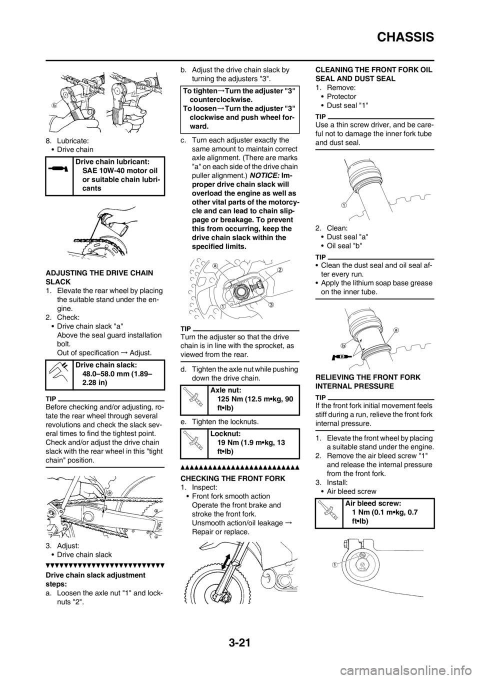
ADJUSTING THE DRIVE CHAIN
SLACK
1. Elevate the rear wheel by placing
the suitable stand under the en-
gine.
2. Check:
• Drive chain slack "a"
Above the seal guard installation
bolt.
Out of specification→Adjust.
Before checking and/or adjusting, ro-
tate the rear wheel through several
revolutions and check the slack sev-
eral times to find the tightest point.
Check and/or adjust the drive chain
slack with the rear wheel in this "tight
chain" position.
3. Adjust:
• Drive chain slack
Drive chain slack adjustment
steps:
a. Loosen the axle nut "1" and lock-
nuts "2".b. Adjust the drive chain slack by
turning the adjusters "3".
c. Turn each adjuster exactly the
same amount to maintain correct
axle alignment. (There are marks
"a" on each side of the drive chain
puller alignment.) NOTICE: Im-
proper drive chain slack will
overload the engine as well as
other vital parts of the motorcy-
cle and can lead to chain slip-
page or breakage. To prevent
this from occurring, keep the
drive chain slack within the
specified limits.
Turn the adjuster so that the drive
chain is in line with the sprocket, as
viewed from the rear.
d. Tighten the axle nut while pushing
down the drive chain.
e. Tighten the locknuts.
CHECKING THE FRONT FORK
1. Inspect:
• Front fork smooth action
Operate the front brake and
stroke the front fork.
Unsmooth action/oil leakage→
Repair or replace.CLEANING THE FRONT FORK OIL
SEAL AND DUST SEAL
1. Remove:
•Protector
• Dust seal "1"
Use a thin screw driver, and be care-
ful not to damage the inner fork tube
and dust seal.
2. Clean:
• Dust seal "a"
• Oil seal "b"
• Clean the dust seal and oil seal af-
ter every run.
• Apply the lithium soap base grease
on the inner tube.
RELIEVING THE FRONT FORK
INTERNAL PRESSURE
If the front fork initial movement feels
stiff during a run, relieve the front fork
internal pressure.
1. Elevate the front wheel by placing
a suitable stand under the engine.
2. Remove the air bleed screw "1"
and release the internal pressure
from the front fork.
3. Install:
• Air bleed screw Drive chain lubricant:
SAE 10W-40 motor oil
or suitable chain lubri-
cants
Drive chain slack:
48.0–58.0 mm (1.89–
2.28 in)
To tighten→Turn the adjuster "3"
counterclockwise.
To loosen→Turn the adjuster "3"
clockwise and push wheel for-
ward.
Axle nut:
125 Nm (12.5 m•kg, 90
ft•lb)
Locknut:
19 Nm (1.9 m•kg, 13
ft•lb)
Air bleed screw:
1 Nm (0.1 m•kg, 0.7
ft•lb)
Page 81 of 230
3-22
CHASSIS
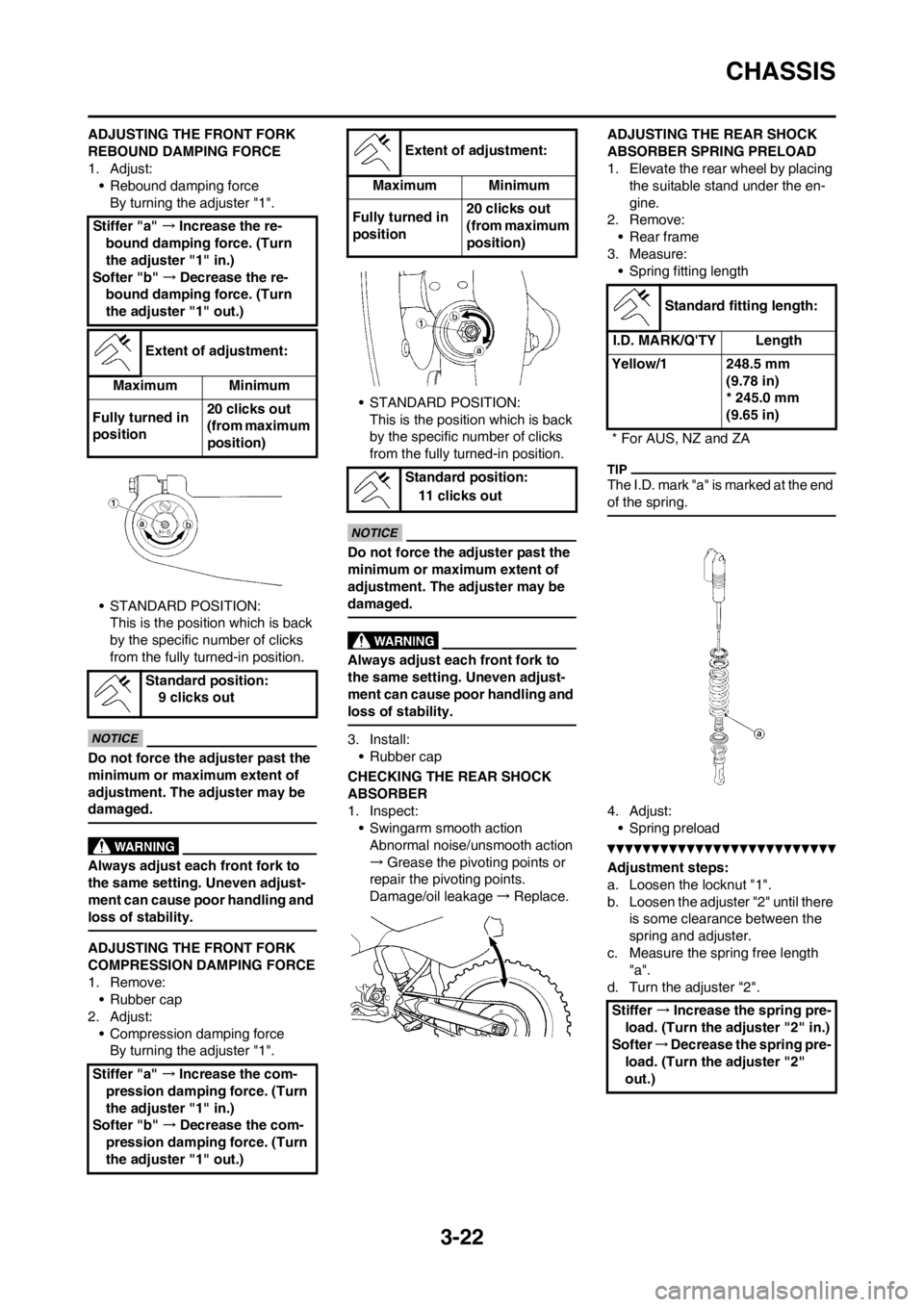
ADJUSTING THE FRONT FORK
REBOUND DAMPING FORCE
1. Adjust:
• Rebound damping force
By turning the adjuster "1".
• STANDARD POSITION:
This is the position which is back
by the specific number of clicks
from the fully turned-in position.
Do not force the adjuster past the
minimum or maximum extent of
adjustment. The adjuster may be
damaged.
Always adjust each front fork to
the same setting. Uneven adjust-
ment can cause poor handling and
loss of stability.
ADJUSTING THE FRONT FORK
COMPRESSION DAMPING FORCE
1. Remove:
• Rubber cap
2. Adjust:
• Compression damping force
By turning the adjuster "1".• STANDARD POSITION:
This is the position which is back
by the specific number of clicks
from the fully turned-in position.
Do not force the adjuster past the
minimum or maximum extent of
adjustment. The adjuster may be
damaged.
Always adjust each front fork to
the same setting. Uneven adjust-
ment can cause poor handling and
loss of stability.
3. Install:
• Rubber cap
CHECKING THE REAR SHOCK
ABSORBER
1. Inspect:
• Swingarm smooth action
Abnormal noise/unsmooth action
→Grease the pivoting points or
repair the pivoting points.
Damage/oil leakage→Replace.ADJUSTING THE REAR SHOCK
ABSORBER SPRING PRELOAD
1. Elevate the rear wheel by placing
the suitable stand under the en-
gine.
2. Remove:
• Rear frame
3. Measure:
• Spring fitting length
The I.D. mark "a" is marked at the end
of the spring.
4. Adjust:
• Spring preload
Adjustment steps:
a. Loosen the locknut "1".
b. Loosen the adjuster "2" until there
is some clearance between the
spring and adjuster.
c. Measure the spring free length
"a".
d. Turn the adjuster "2". Stiffer "a" →Increase the re-
bound damping force. (Turn
the adjuster "1" in.)
Softer "b" →Decrease the re-
bound damping force. (Turn
the adjuster "1" out.)
Extent of adjustment:
Maximum Minimum
Fully turned in
position20 clicks out
(from maximum
position)
Standard position:
9 clicks out
Stiffer "a" →Increase the com-
pression damping force. (Turn
the adjuster "1" in.)
Softer "b" →Decrease the com-
pression damping force. (Turn
the adjuster "1" out.)
Extent of adjustment:
Maximum Minimum
Fully turned in
position20 clicks out
(from maximum
position)
Standard position:
11 clicks out
Standard fitting length:
I.D. MARK/Q'TY Length
Yellow/1 248.5 mm
(9.78 in)
* 245.0 mm
(9.65 in)
* For AUS, NZ and ZA
Stiffer →Increase the spring pre-
load. (Turn the adjuster "2" in.)
Softer→Decrease the spring pre-
load. (Turn the adjuster "2"
out.)
Page 83 of 230
3-24
CHASSIS
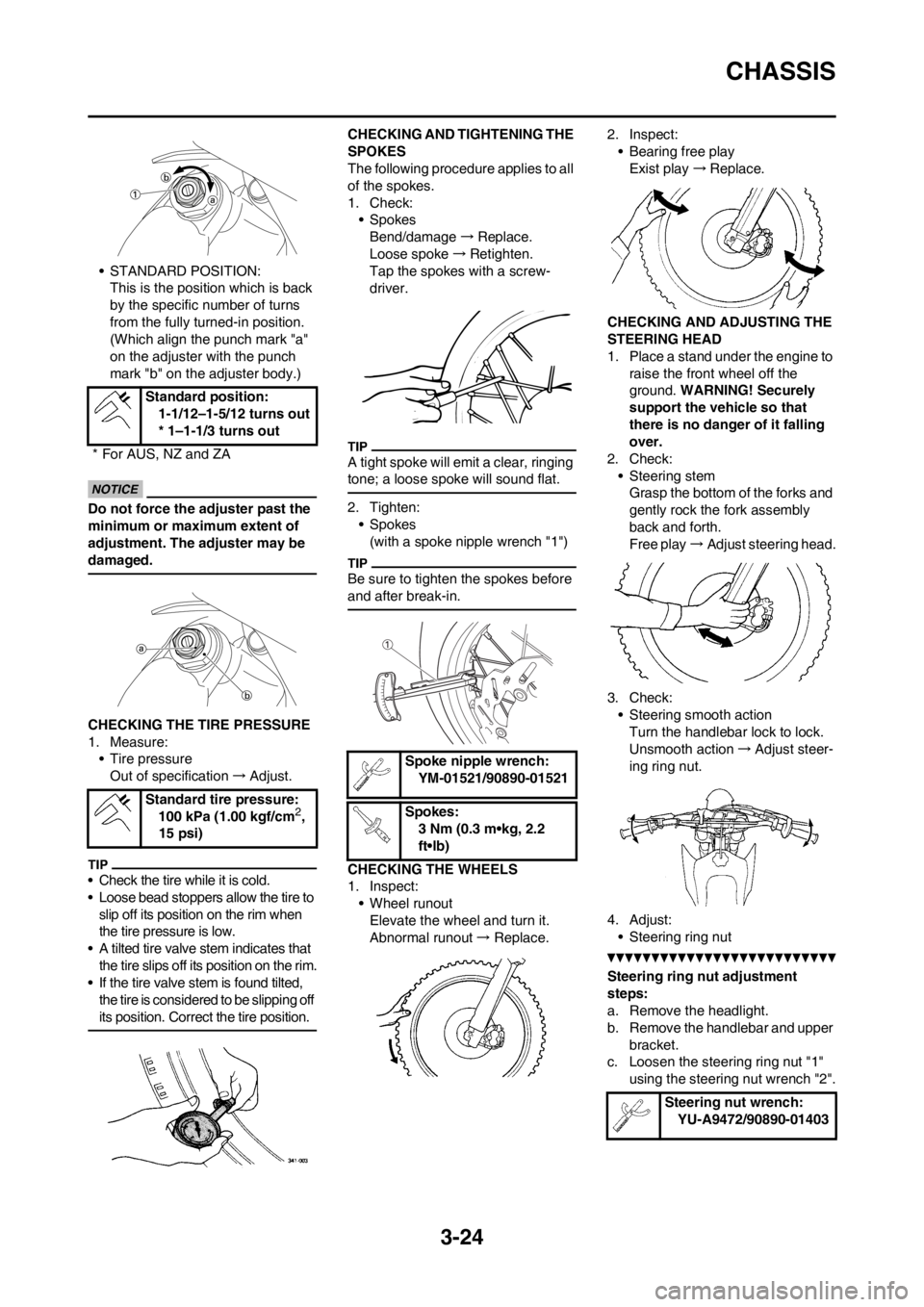
• STANDARD POSITION:
This is the position which is back
by the specific number of turns
from the fully turned-in position.
(Which align the punch mark "a"
on the adjuster with the punch
mark "b" on the adjuster body.)
Do not force the adjuster past the
minimum or maximum extent of
adjustment. The adjuster may be
damaged.
CHECKING THE TIRE PRESSURE
1. Measure:
• Tire pressure
Out of specification→Adjust.
• Check the tire while it is cold.
• Loose bead stoppers allow the tire to
slip off its position on the rim when
the tire pressure is low.
• A tilted tire valve stem indicates that
the tire slips off its position on the rim.
• If the tire valve stem is found tilted,
the tire is considered to be slipping off
its position. Correct the tire position.
CHECKING AND TIGHTENING THE
SPOKES
The following procedure applies to all
of the spokes.
1. Check:
• Spokes
Bend/damage→Replace.
Loose spoke→Retighten.
Tap the spokes with a screw-
driver.
A tight spoke will emit a clear, ringing
tone; a loose spoke will sound flat.
2. Tighten:
• Spokes
(with a spoke nipple wrench "1")
Be sure to tighten the spokes before
and after break-in.
CHECKING THE WHEELS
1. Inspect:
• Wheel runout
Elevate the wheel and turn it.
Abnormal runout→ Replace.2. Inspect:
• Bearing free play
Exist play→Replace.
CHECKING AND ADJUSTING THE
STEERING HEAD
1. Place a stand under the engine to
raise the front wheel off the
ground. WARNING! Securely
support the vehicle so that
there is no danger of it falling
over.
2. Check:
• Steering stem
Grasp the bottom of the forks and
gently rock the fork assembly
back and forth.
Free play→Adjust steering head.
3. Check:
• Steering smooth action
Turn the handlebar lock to lock.
Unsmooth action→Adjust steer-
ing ring nut.
4. Adjust:
• Steering ring nut
Steering ring nut adjustment
steps:
a. Remove the headlight.
b. Remove the handlebar and upper
bracket.
c. Loosen the steering ring nut "1"
using the steering nut wrench "2". Standard position:
1-1/12–1-5/12 turns out
* 1–1-1/3 turns out
* For AUS, NZ and ZA
Standard tire pressure:
100 kPa (1.00 kgf/cm
2,
15 psi)
Spoke nipple wrench:
YM-01521/90890-01521
Spokes:
3 Nm (0.3 m•kg, 2.2
ft•lb)
Steering nut wrench:
YU-A9472/90890-01403
Page 96 of 230
4-5
CHASSIS
CHASSIS
SELECTION OF THE SECONDARY
REDUCTION RATIO (SPROCKET)
• It is generally said that the second-
ary gear ratio should be reduced for
a longer straight portion of a speed
course and should be increased for
a course with many corners. Actual-
ly, however, as the speed depends
on the ground condition of the day
of the ride, be sure to run through
the circuit to set the machine suit-
able for the entire course.
• In actuality, it is very difficult to
achieve settings suitable for the en-
tire course and some settings may
be sacrificed. Thus, the settings
should be matched to the portion of
the course that has the greatest ef-
fect on the ride result. In such a
case, run through the entire course
while making notes of lap times to
find the best balance; then, deter-
mine the secondary reduction ratio.
• If a course has a long straight por-
tion where a machine can run at
maximum speed, the machine is
generally set such that it can devel-
op its maximum revolutions toward
the end of the straight line, with care
taken to avoid the engine over-rev-
ving.
Riding technique varies from rider to
rider and the performance of a ma-
chine also vary from machine to ma-
chine. Therefore, do not imitate other
rider's settings from the beginning but
choose your own setting according to
the level of your riding technique.
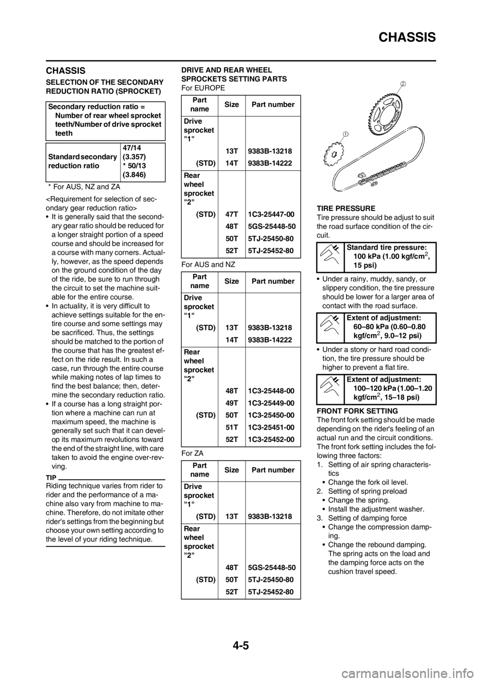
DRIVE AND REAR WHEEL
SPROCKETS SETTING PARTS
For EUROPE
For AUS and NZ
For ZATIRE PRESSURE
Tire pressure should be adjust to suit
the road surface condition of the cir-
cuit.
• Under a rainy, muddy, sandy, or
slippery condition, the tire pressure
should be lower for a larger area of
contact with the road surface.
• Under a stony or hard road condi-
tion, the tire pressure should be
higher to prevent a flat tire.
FRONT FORK SETTING
The front fork setting should be made
depending on the rider's feeling of an
actual run and the circuit conditions.
The front fork setting includes the fol-
lowing three factors:
1. Setting of air spring characteris-
tics
• Change the fork oil level.
2. Setting of spring preload
• Change the spring.
• Install the adjustment washer.
3. Setting of damping force
• Change the compression damp-
ing.
• Change the rebound damping.
The spring acts on the load and
the damping force acts on the
cushion travel speed. Secondary reduction ratio =
Number of rear wheel sprocket
teeth/Number of drive sprocket
teeth
Standard secondary
reduction ratio47/14
(3.357)
* 50/13
(3.846)
* For AUS, NZ and ZA
Part
nameSize Part number
Drive
sprocket
"1"
13T 9383B-13218
(STD) 14T 9383B-14222
Rear
wheel
sprocket
"2"
(STD) 47T 1C3-25447-00
48T 5GS-25448-50
50T 5TJ-25450-80
52T 5TJ-25452-80
Part
nameSize Part number
Drive
sprocket
"1"
(STD) 13T 9383B-13218
14T 9383B-14222
Rear
wheel
sprocket
"2"
48T 1C3-25448-00
49T 1C3-25449-00
(STD) 50T 1C3-25450-00
51T 1C3-25451-00
52T 1C3-25452-00
Part
nameSize Part number
Drive
sprocket
"1"
(STD) 13T 9383B-13218
Rear
wheel
sprocket
"2"
48T 5GS-25448-50
(STD) 50T 5TJ-25450-80
52T 5TJ-25452-80
Standard tire pressure:
100 kPa (1.00 kgf/cm2,
15 psi)
Extent of adjustment:
60–80 kPa (0.60–0.80
kgf/cm
2, 9.0–12 psi)
Extent of adjustment:
100–120 kPa (1.00–1.20
kgf/cm
2, 15–18 psi)
Page 98 of 230
4-7
CHASSIS
REAR SUSPENSION SETTING
The rear suspension setting should
be made depending on the rider's
feeling of an actual run and the circuit
conditions.
The rear suspension setting includes
the following two factors:
1. Setting of spring preload
• Change the set length of the
spring.
• Change the spring.
2. Setting of damping force
• Change the rebound damping.
• Change the compression damp-
ing.
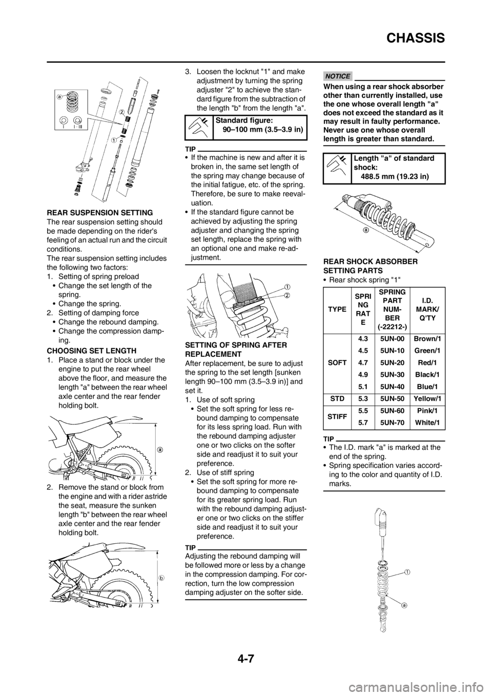
CHOOSING SET LENGTH
1. Place a stand or block under the
engine to put the rear wheel
above the floor, and measure the
length "a" between the rear wheel
axle center and the rear fender
holding bolt.
2. Remove the stand or block from
the engine and with a rider astride
the seat, measure the sunken
length "b" between the rear wheel
axle center and the rear fender
holding bolt.3. Loosen the locknut "1" and make
adjustment by turning the spring
adjuster "2" to achieve the stan-
dard figure from the subtraction of
the length "b" from the length "a".
• If the machine is new and after it is
broken in, the same set length of
the spring may change because of
the initial fatigue, etc. of the spring.
Therefore, be sure to make reeval-
uation.
• If the standard figure cannot be
achieved by adjusting the spring
adjuster and changing the spring
set length, replace the spring with
an optional one and make re-ad-
justment.
SETTING OF SPRING AFTER
REPLACEMENT
After replacement, be sure to adjust
the spring to the set length [sunken
length 90–100 mm (3.5–3.9 in)] and
set it.
1. Use of soft spring
• Set the soft spring for less re-
bound damping to compensate
for its less spring load. Run with
the rebound damping adjuster
one or two clicks on the softer
side and readjust it to suit your
preference.
2. Use of stiff spring
• Set the soft spring for more re-
bound damping to compensate
for its greater spring load. Run
with the rebound damping adjust-
er one or two clicks on the stiffer
side and readjust it to suit your
preference.
Adjusting the rebound damping will
be followed more or less by a change
in the compression damping. For cor-
rection, turn the low compression
damping adjuster on the softer side.
When using a rear shock absorber
other than currently installed, use
the one whose overall length "a"
does not exceed the standard as it
may result in faulty performance.
Never use one whose overall
length is greater than standard.
REAR SHOCK ABSORBER
SETTING PARTS
• Rear shock spring "1"
• The I.D. mark "a" is marked at the
end of the spring.
• Spring specification varies accord-
ing to the color and quantity of I.D.
marks.
Standard figure:
90–100 mm (3.5–3.9 in)
Length "a" of standard
shock:
488.5 mm (19.23 in)
TYPESPRI
NG
RAT
ESPRING
PART
NUM-
BER
(-22212-)I.D.
MARK/
Q'TY
SOFT4.3 5UN-00 Brown/1
4.5 5UN-10 Green/1
4.7 5UN-20 Red/1
4.9 5UN-30 Black/1
5.1 5UN-40 Blue/1
STD 5.3 5UN-50 Yellow/1
STIFF5.5 5UN-60 Pink/1
5.7 5UN-70 White/1