YAMAHA WR 250F 2014 Owners Manual
Manufacturer: YAMAHA, Model Year: 2014, Model line: WR 250F, Model: YAMAHA WR 250F 2014Pages: 230, PDF Size: 13.01 MB
Page 201 of 230
6-34
SWINGARM
• Apply the molybdenum disulfide
grease on the bearing when install-
ing.
• Install the bearing by pressing it on
the side having the manufacture's
marks or numbers.
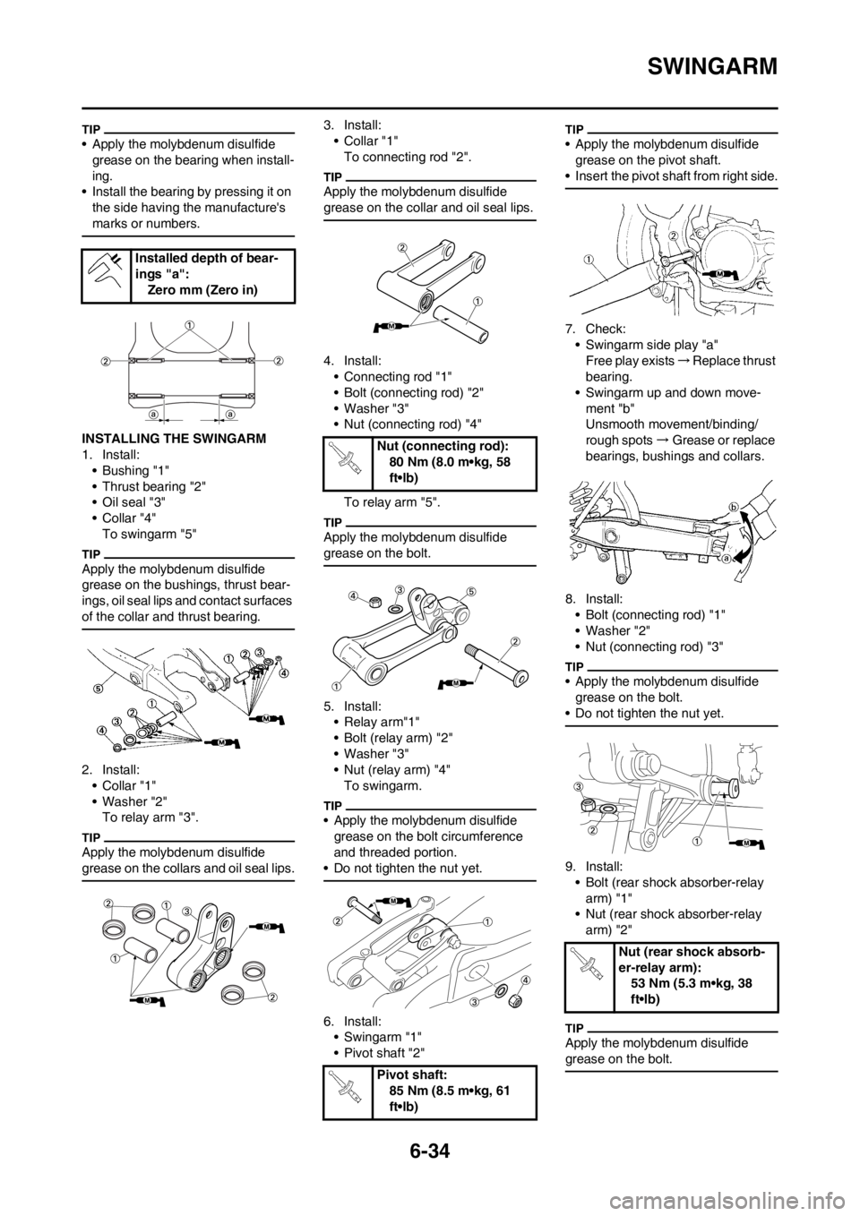
INSTALLING THE SWINGARM
1. Install:
• Bushing "1"
• Thrust bearing "2"
• Oil seal "3"
•Collar "4"
To swingarm "5"
Apply the molybdenum disulfide
grease on the bushings, thrust bear-
ings, oil seal lips and contact surfaces
of the collar and thrust bearing.
2. Install:
•Collar "1"
• Washer "2"
To relay arm "3".
Apply the molybdenum disulfide
grease on the collars and oil seal lips.
3. Install:
• Collar "1"
To connecting rod "2".
Apply the molybdenum disulfide
grease on the collar and oil seal lips.
4. Install:
• Connecting rod "1"
• Bolt (connecting rod) "2"
• Washer "3"
• Nut (connecting rod) "4"
To relay arm "5".
Apply the molybdenum disulfide
grease on the bolt.
5. Install:
• Relay arm"1"
• Bolt (relay arm) "2"
• Washer "3"
• Nut (relay arm) "4"
To swingarm.
• Apply the molybdenum disulfide
grease on the bolt circumference
and threaded portion.
• Do not tighten the nut yet.
6. Install:
• Swingarm "1"
• Pivot shaft "2"
• Apply the molybdenum disulfide
grease on the pivot shaft.
• Insert the pivot shaft from right side.
7. Check:
• Swingarm side play "a"
Free play exists→Replace thrust
bearing.
• Swingarm up and down move-
ment "b"
Unsmooth movement/binding/
rough spots →Grease or replace
bearings, bushings and collars.
8. Install:
• Bolt (connecting rod) "1"
• Washer "2"
• Nut (connecting rod) "3"
• Apply the molybdenum disulfide
grease on the bolt.
• Do not tighten the nut yet.
9. Install:
• Bolt (rear shock absorber-relay
arm) "1"
• Nut (rear shock absorber-relay
arm) "2"
Apply the molybdenum disulfide
grease on the bolt.
Installed depth of bear-
ings "a":
Zero mm (Zero in)
Nut (connecting rod):
80 Nm (8.0 m•kg, 58
ft•lb)
Pivot shaft:
85 Nm (8.5 m•kg, 61
ft•lb)
Nut (rear shock absorb-
er-relay arm):
53 Nm (5.3 m•kg, 38
ft•lb)
Page 202 of 230
6-35
SWINGARM
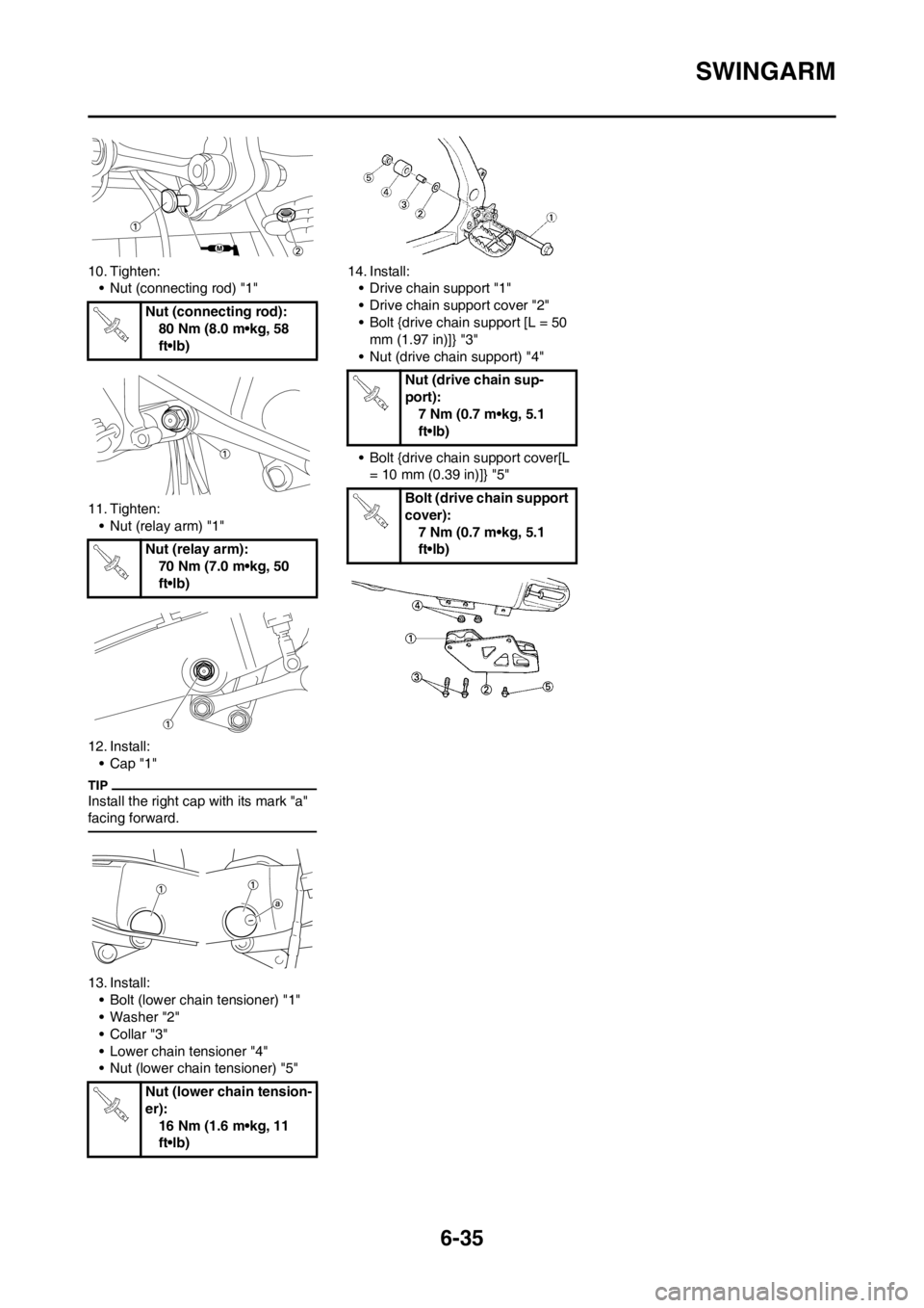
10. Tighten:
• Nut (connecting rod) "1"
11. Tighten:
• Nut (relay arm) "1"
12. Install:
•Cap "1"
Install the right cap with its mark "a"
facing forward.
13. Install:
• Bolt (lower chain tensioner) "1"
• Washer "2"
•Collar "3"
• Lower chain tensioner "4"
• Nut (lower chain tensioner) "5"14. Install:
• Drive chain support "1"
• Drive chain support cover "2"
• Bolt {drive chain support [L = 50
mm (1.97 in)]} "3"
• Nut (drive chain support) "4"
• Bolt {drive chain support cover[L
= 10 mm (0.39 in)]} "5" Nut (connecting rod):
80 Nm (8.0 m•kg, 58
ft•lb)
Nut (relay arm):
70 Nm (7.0 m•kg, 50
ft•lb)
Nut (lower chain tension-
er):
16 Nm (1.6 m•kg, 11
ft•lb)
Nut (drive chain sup-
port):
7 Nm (0.7 m•kg, 5.1
ft•lb)
Bolt (drive chain support
cover):
7 Nm (0.7 m•kg, 5.1
ft•lb)
Page 203 of 230
6-36
REAR SHOCK ABSORBER
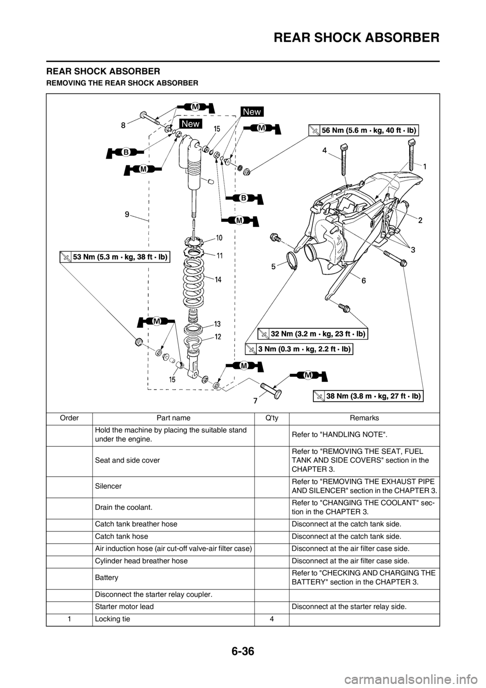
REAR SHOCK ABSORBER
REMOVING THE REAR SHOCK ABSORBER
Order Part name Q'ty Remarks
Hold the machine by placing the suitable stand
under the engine.Refer to "HANDLING NOTE".
Seat and side cover Refer to "REMOVING THE SEAT, FUEL
TANK AND SIDE COVERS" section in the
CHAPTER 3.
Silencer Refer to "REMOVING THE EXHAUST PIPE
AND SILENCER" section in the CHAPTER 3.
Drain the coolant.Refer to "CHANGING THE COOLANT" sec-
tion in the CHAPTER 3.
Catch tank breather hose Disconnect at the catch tank side.
Catch tank hose Disconnect at the catch tank side.
Air induction hose (air cut-off valve-air filter case) Disconnect at the air filter case side.
Cylinder head breather hose Disconnect at the air filter case side.
BatteryRefer to "CHECKING AND CHARGING THE
BATTERY" section in the CHAPTER 3.
Disconnect the starter relay coupler.
Starter motor lead Disconnect at the starter relay side.
1 Locking tie 4
Page 204 of 230
6-37
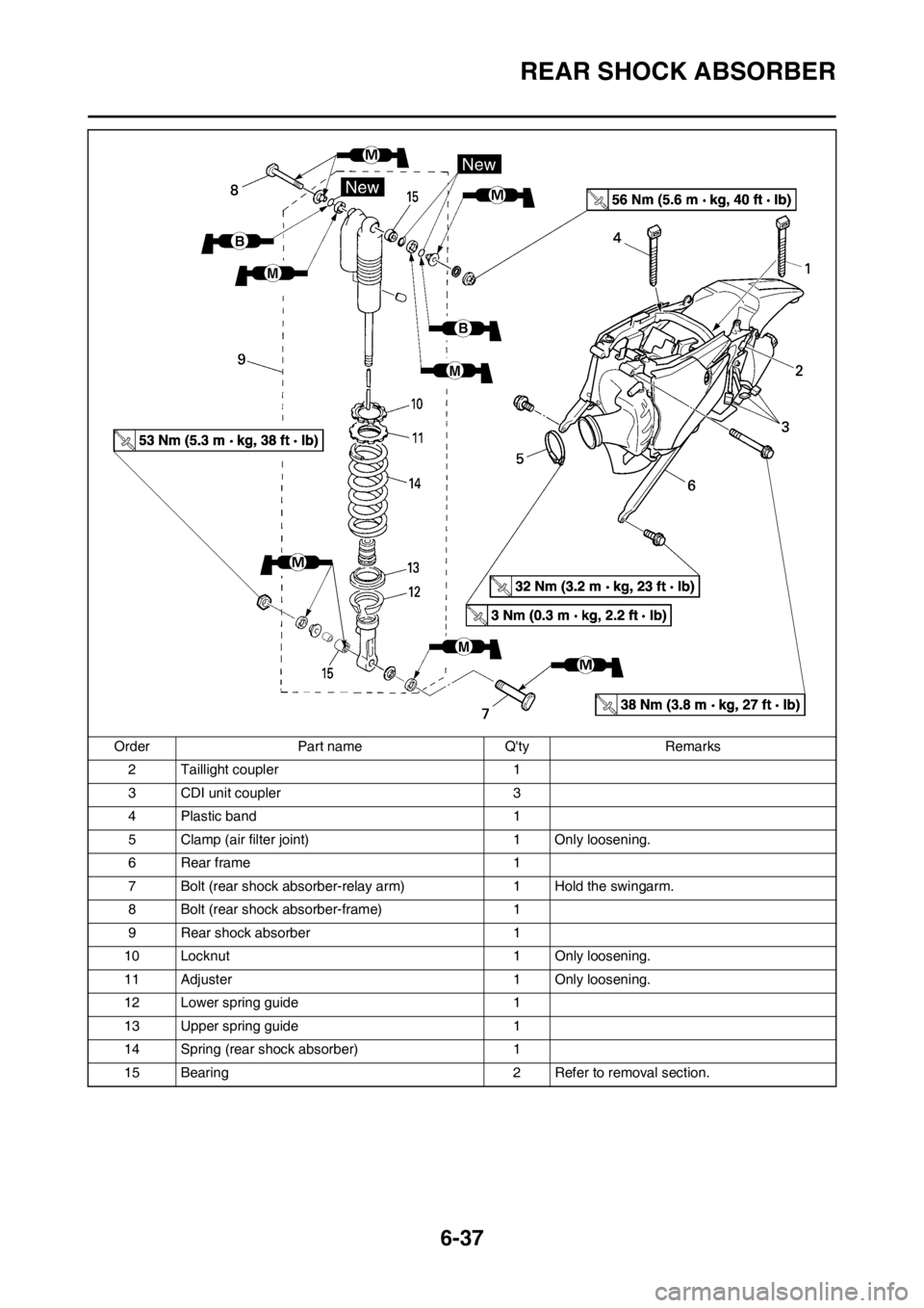
REAR SHOCK ABSORBER
2 Taillight coupler 1
3 CDI unit coupler 3
4 Plastic band 1
5 Clamp (air filter joint) 1 Only loosening.
6Rear frame 1
7 Bolt (rear shock absorber-relay arm) 1 Hold the swingarm.
8 Bolt (rear shock absorber-frame) 1
9 Rear shock absorber 1
10 Locknut 1 Only loosening.
11 Adjuster 1 Only loosening.
12 Lower spring guide 1
13 Upper spring guide 1
14 Spring (rear shock absorber) 1
15 Bearing 2 Refer to removal section. Order Part name Q'ty Remarks
Page 205 of 230
6-38
REAR SHOCK ABSORBER
HANDLING NOTE
• Support the machine securely so
there is no danger of it falling
over.
• This rear shock absorber is pro-
vided with a separate type tank
filled with high-pressure nitro-
gen gas. To prevent the danger
of explosion, read and under-
stand the following information
before handling the shock ab-
sorber. The manufacturer can
not be held responsible for prop-
erty damage or personal injury
that may result from improper
handling.
• Never tamper or attempt to dis-
assemble the cylinder or the
tank.
• Never throw the rear shock ab-
sorber into an open flame or
other high heat. The rear shock
absorber may explode as a re-
sult of nitrogen gas expansion
and/ or damage to the hose.
• Be careful not to damage any
part of the gas tank. A damaged
gas tank will impair the damp-
ing performance or cause a
malfunction.
• Take care not to scratch the
contact surface of the piston
rod with the cylinder; or oil
could leak out.
• Never attempt to remove the
plug at the bottom of the nitro-
gen gas tank. It is very danger-
ous to remove the plug.
• When scrapping the rear shock
absorber, follow the instruc-
tions on disposal.
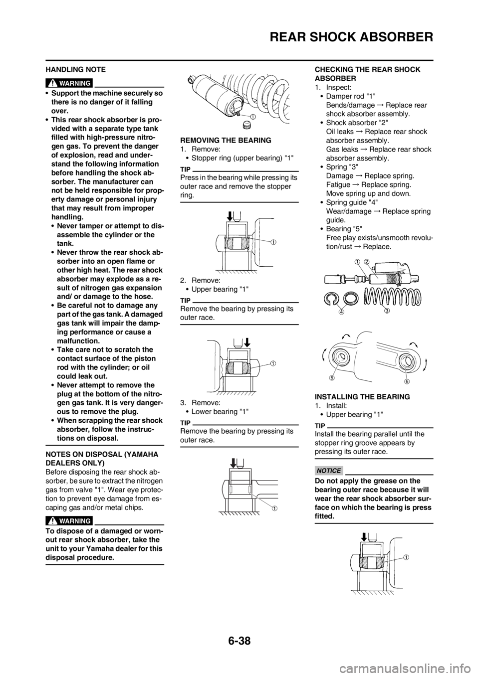
NOTES ON DISPOSAL (YAMAHA
DEALERS ONLY)
Before disposing the rear shock ab-
sorber, be sure to extract the nitrogen
gas from valve "1". Wear eye protec-
tion to prevent eye damage from es-
caping gas and/or metal chips.
To dispose of a damaged or worn-
out rear shock absorber, take the
unit to your Yamaha dealer for this
disposal procedure.
REMOVING THE BEARING
1. Remove:
• Stopper ring (upper bearing) "1"
Press in the bearing while pressing its
outer race and remove the stopper
ring.
2. Remove:
• Upper bearing "1"
Remove the bearing by pressing its
outer race.
3. Remove:
• Lower bearing "1"
Remove the bearing by pressing its
outer race.
CHECKING THE REAR SHOCK
ABSORBER
1. Inspect:
• Damper rod "1"
Bends/damage→Replace rear
shock absorber assembly.
• Shock absorber "2"
Oil leaks→Replace rear shock
absorber assembly.
Gas leaks→Replace rear shock
absorber assembly.
• Spring "3"
Damage→Replace spring.
Fatigue→Replace spring.
Move spring up and down.
• Spring guide "4"
Wear/damage→Replace spring
guide.
• Bearing "5"
Free play exists/unsmooth revolu-
tion/rust →Replace.
INSTALLING THE BEARING
1. Install:
• Upper bearing "1"
Install the bearing parallel until the
stopper ring groove appears by
pressing its outer race.
Do not apply the grease on the
bearing outer race because it will
wear the rear shock absorber sur-
face on which the bearing is press
fitted.
Page 206 of 230
6-39
REAR SHOCK ABSORBER
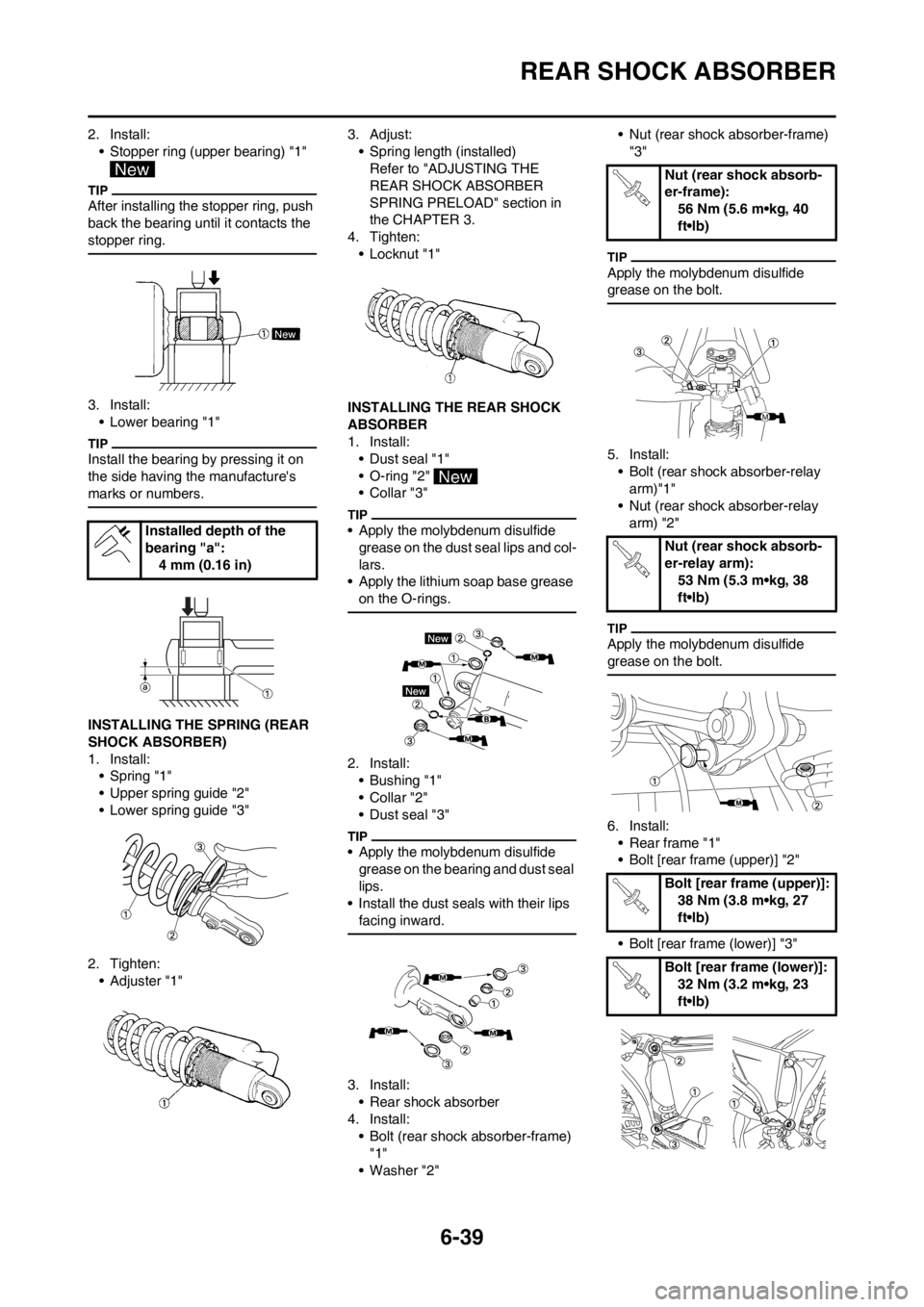
2. Install:
• Stopper ring (upper bearing) "1"
After installing the stopper ring, push
back the bearing until it contacts the
stopper ring.
3. Install:
• Lower bearing "1"
Install the bearing by pressing it on
the side having the manufacture's
marks or numbers.
INSTALLING THE SPRING (REAR
SHOCK ABSORBER)
1. Install:
• Spring "1"
• Upper spring guide "2"
• Lower spring guide "3"
2. Tighten:
•Adjuster "1"3. Adjust:
• Spring length (installed)
Refer to "ADJUSTING THE
REAR SHOCK ABSORBER
SPRING PRELOAD" section in
the CHAPTER 3.
4. Tighten:
• Locknut "1"
INSTALLING THE REAR SHOCK
ABSORBER
1. Install:
• Dust seal "1"
• O-ring "2"
• Collar "3"
• Apply the molybdenum disulfide
grease on the dust seal lips and col-
lars.
• Apply the lithium soap base grease
on the O-rings.
2. Install:
• Bushing "1"
• Collar "2"
• Dust seal "3"
• Apply the molybdenum disulfide
grease on the bearing and dust seal
lips.
• Install the dust seals with their lips
facing inward.
3. Install:
• Rear shock absorber
4. Install:
• Bolt (rear shock absorber-frame)
"1"
• Washer "2"• Nut (rear shock absorber-frame)
"3"
Apply the molybdenum disulfide
grease on the bolt.
5. Install:
• Bolt (rear shock absorber-relay
arm)"1"
• Nut (rear shock absorber-relay
arm) "2"
Apply the molybdenum disulfide
grease on the bolt.
6. Install:
• Rear frame "1"
• Bolt [rear frame (upper)] "2"
• Bolt [rear frame (lower)] "3" Installed depth of the
bearing "a":
4 mm (0.16 in)
Nut (rear shock absorb-
er-frame):
56 Nm (5.6 m•kg, 40
ft•lb)
Nut (rear shock absorb-
er-relay arm):
53 Nm (5.3 m•kg, 38
ft•lb)
Bolt [rear frame (upper)]:
38 Nm (3.8 m•kg, 27
ft•lb)
Bolt [rear frame (lower)]:
32 Nm (3.2 m•kg, 23
ft•lb)
Page 207 of 230
6-40
REAR SHOCK ABSORBER
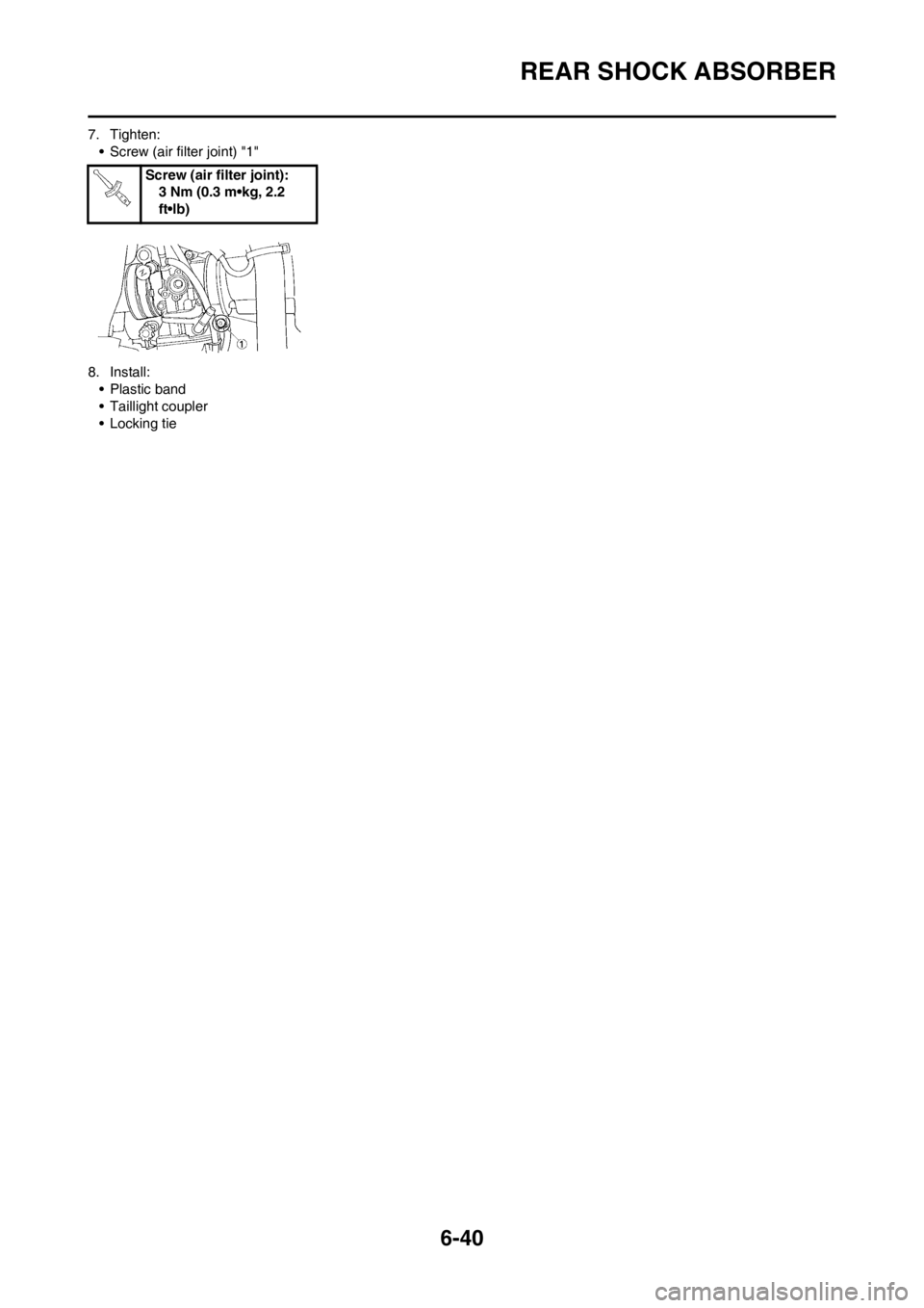
7. Tighten:
• Screw (air filter joint) "1"
8. Install:
• Plastic band
• Taillight coupler
• Locking tieScrew (air filter joint):
3 Nm (0.3 m•kg, 2.2
ft•lb)
Page 208 of 230
7-1
ELECTRICAL COMPONENTS AND WIRING DIAGRAM
ELECTRICAL
This section is intended for those who have basic knowledge and skill concerning the servicing of Yamaha motorcycles
(e.g., Yamaha dealers, service engineers, etc.) Those who have little knowledge and skill concerning servicing are request-
ed not to undertake inspection, adjustment, disassembly, or reassembly only by reference to this manual. It may lead to
servicing trouble and mechanical damage.
ELECTRICAL COMPONENTS AND WIRING DIAGRAM
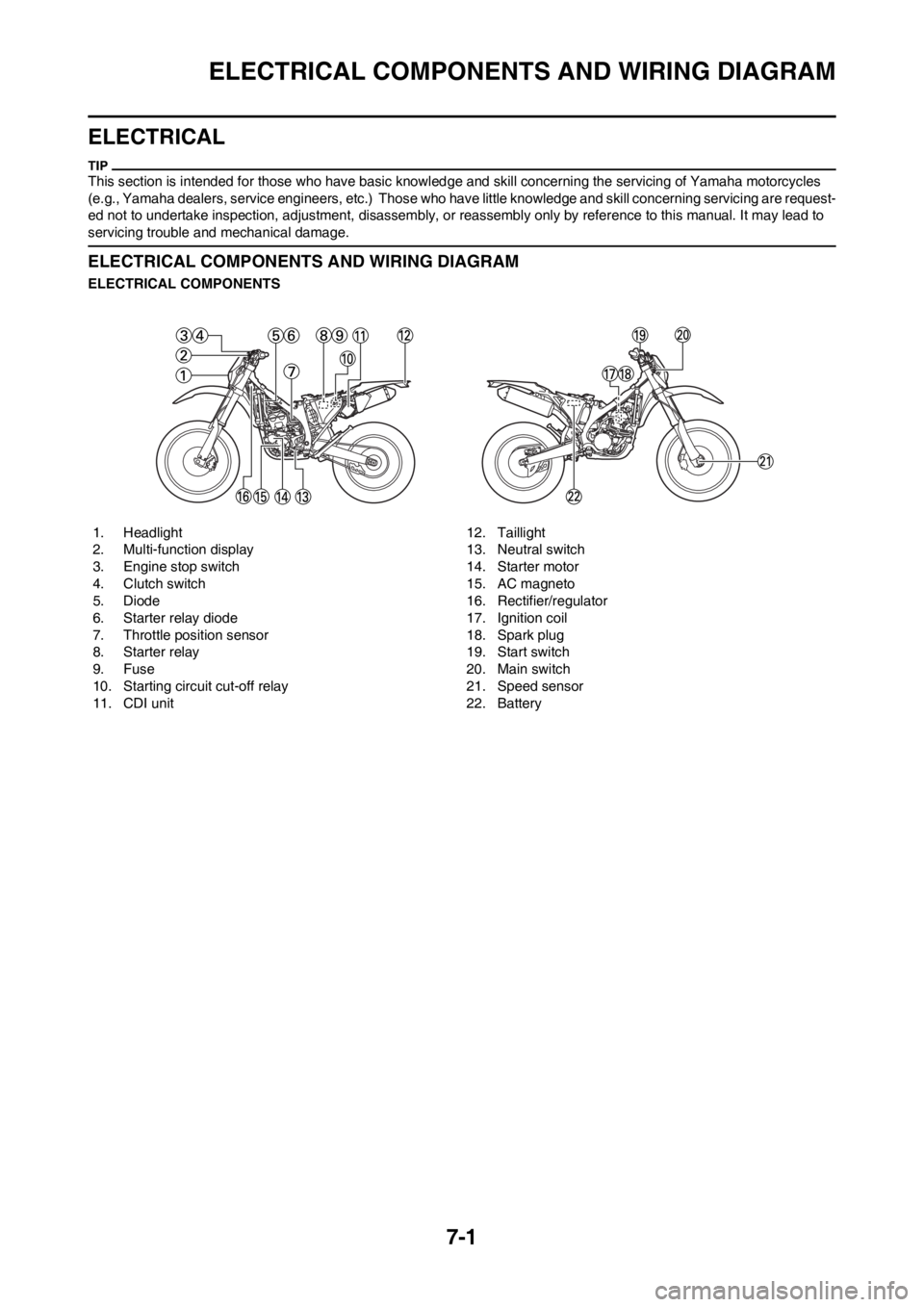
ELECTRICAL COMPONENTS
1. Headlight
2. Multi-function display
3. Engine stop switch
4. Clutch switch
5. Diode
6. Starter relay diode
7. Throttle position sensor
8. Starter relay
9. Fuse
10. Starting circuit cut-off relay
11. CDI unit12. Taillight
13. Neutral switch
14. Starter motor
15. AC magneto
16. Rectifier/regulator
17. Ignition coil
18. Spark plug
19. Start switch
20. Main switch
21. Speed sensor
22. Battery
Page 209 of 230
7-2
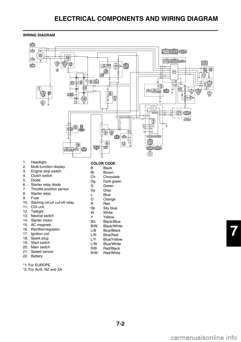
ELECTRICAL COMPONENTS AND WIRING DIAGRAM
WIRING DIAGRAM
1. Headlight
2. Multi-function display
3. Engine stop switch
4. Clutch switch
5. Diode
6. Starter relay diode
7. Throttle position sensor
8. Starter relay
9. Fuse
10. Starting circuit cut-off relay
11. CDI unit
12. Taillight
13. Neutral switch
14. Starter motor
15. AC magneto
16. Rectifier/regulator
17. Ignition coil
18. Spark plug
19. Start switch
20. Main switch
21. Speed sensor
22. Battery
*1: For EUROPE
*2: For AUS, NZ and ZACOLOR CODE
BBlack
Br Brown
Ch Chocolate
Dg Dark green
GGreen
Gy Gray
LBlue
O Orange
RRed
Sb Sky blue
WWhite
YYellow
B/L Black/Blue
B/W Black/White
L/B Blue/Black
L/R Blue/Red
L/Y Blue/Yellow
L/W Blue/White
R/B Red/Black
R/W Red/White
7
Page 210 of 230
7-3
IGNITION SYSTEM
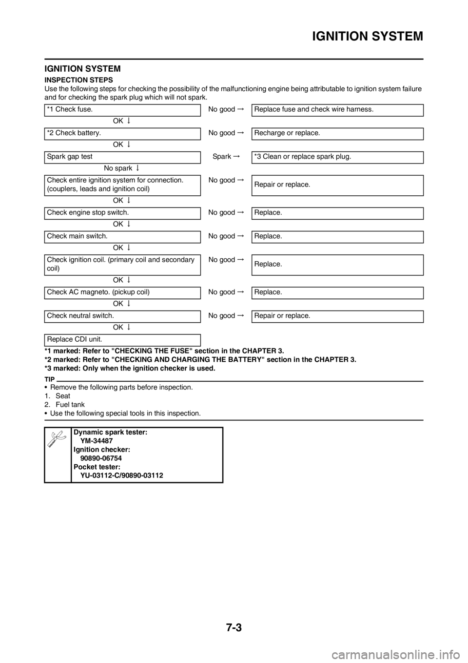
IGNITION SYSTEM
INSPECTION STEPS
Use the following steps for checking the possibility of the malfunctioning engine being attributable to ignition system failure
and for checking the spark plug which will not spark.
*1 marked: Refer to "CHECKING THE FUSE" section in the CHAPTER 3.
*2 marked: Refer to "CHECKING AND CHARGING THE BATTERY" section in the CHAPTER 3.
*3 marked: Only when the ignition checker is used.
• Remove the following parts before inspection.
1. Seat
2. Fuel tank
• Use the following special tools in this inspection.
*1 Check fuse. No good→Replace fuse and check wire harness.
OK↓
*2 Check battery. No good→Recharge or replace.
OK↓
Spark gap test Spark→*3 Clean or replace spark plug.
No spark↓
Check entire ignition system for connection.
(couplers, leads and ignition coil)No good→
Repair or replace.
OK↓
Check engine stop switch. No good→Replace.
OK↓
Check main switch. No good→Replace.
OK↓
Check ignition coil. (primary coil and secondary
coil)No good→
Replace.
OK↓
Check AC magneto. (pickup coil) No good→Replace.
OK↓
Check neutral switch. No good→Repair or replace.
OK↓
Replace CDI unit.
Dynamic spark tester:
YM-34487
Ignition checker:
90890-06754
Pocket tester:
YU-03112-C/90890-03112