ignition YAMAHA WR 250F 2014 Owners Manual
[x] Cancel search | Manufacturer: YAMAHA, Model Year: 2014, Model line: WR 250F, Model: YAMAHA WR 250F 2014Pages: 230, PDF Size: 13.01 MB
Page 10 of 230

CONTENTS
CHAPTER 1
GENERAL INFOR-
MATION
LOCATION OF
IMPORTANT LABELS ..... 1-1
DESCRIPTION ................. 1-4
CONSUMER
INFORMATION................. 1-5
INCLUDED PARTS .......... 1-5
IMPORTANT
INFORMATION................. 1-5
CHECKING OF
CONNECTION .................. 1-6
SPECIAL TOOLS ............. 1-7
CONTROL
FUNCTIONS ................... 1-12
MULTI-FUNCTION
DISPLAY ........................ 1-13
STARTING AND
BREAK-IN ...................... 1-18
TORQUE-CHECK
POINTS........................... 1-20
CLEANING AND
STORAGE ...................... 1-21
CHAPTER 2
SPECIFICATIONS
GENERAL
SPECIFICATIONS ............ 2-1
MAINTENANCE
SPECIFICATIONS ............ 2-3
TIGHTENING
TORQUES ...................... 2-12
LUBRICATION
DIAGRAMS .................... 2-19
CABLE ROUTING
DIAGRAM ....................... 2-21
CHAPTER 3
REGULAR INSPEC-
TION AND AD-
JUSTMENTS
MAINTENANCE INTER-
VALS FOR COMPETITION
USE ................................... 3-1
PRE-OPERATION
INSPECTION AND
MAINTENANCE................ 3-5
ENGINE ............................ 3-6
CHASSIS ........................ 3-17
ELECTRICAL ................. 3-27
CHAPTER 4
TUNING
ENGINE ............................ 4-1
CHASSIS .......................... 4-5
CHAPTER 5
ENGINE
RADIATOR ....................... 5-1
CARBURETOR................. 5-4
AIR INDICTOIN
SYSTEM ......................... 5-12
CAMSHAFTS.................. 5-14
CYLINDER HEAD........... 5-19
VALVES AND VALVE
SPRINGS ........................ 5-21
CYLINDER AND
PISTON ........................... 5-25
CLUTCH ......................... 5-29
OIL FILTER ELEMENT
AND WATER PUMP ....... 5-34
BALANCER .................... 5-39
OIL PUMP ....................... 5-41
KICK SHAFT AND
SHIFT SHAFT ................. 5-44
AC MAGNETO AND
STARTER CLUTCH ....... 5-49ENGINE REMOVAL........5-54
CRANKCASE AND
CRANKSHAFT ...............5-58
TRANSMISSION,
SHIFT CAM AND
SHIFT FORK ...................5-64
CHAPTER 6
CHASSIS
FRONT WHEEL AND
REAR WHEEL ..................6-1
FRONT BRAKE AND
REAR BRAKE ..................6-6
FRONT FORK .................6-16
HANDLEBAR..................6-23
STEERING ......................6-27
SWINGARM ....................6-31
REAR SHOCK
ABSORBER ....................6-36
CHAPTER 7
ELECTRICAL
ELECTRICAL COMPO-
NENTS AND WIRING
DIAGRAM .........................7-1
IGNITION SYSTEM...........7-3
ELECTRIC STARTING
SYSTEM............................7-5
CHARGING SYSTEM .....7-13
THROTTLE POSITION
SENSOR SYSTEM .........7-15
LIGHTING SYSTEM .......7-18
SIGNALING SYSTEM.....7-20
Page 19 of 230
1-9
SPECIAL TOOLS
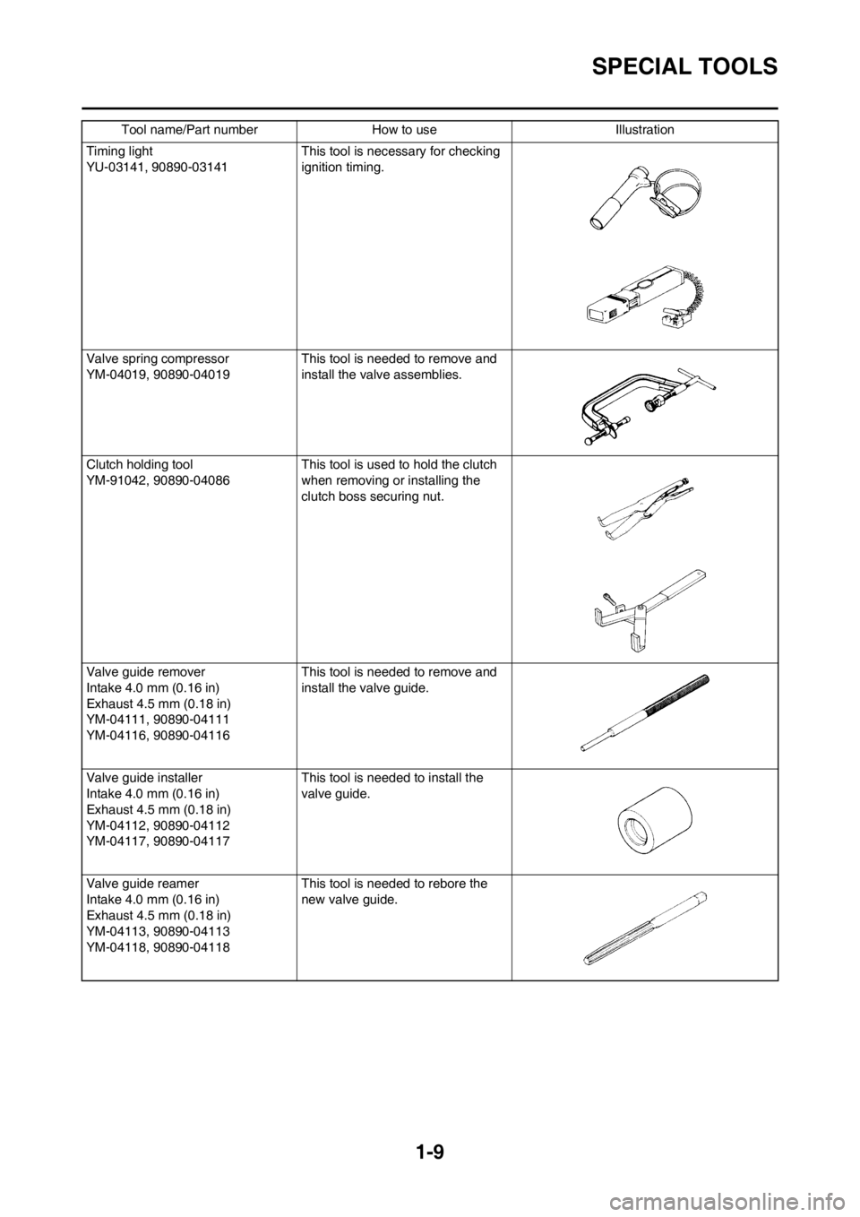
Timing light
YU-03141, 90890-03141 This tool is necessary for checking
ignition timing.
Valve spring compressor
YM-04019, 90890-04019 This tool is needed to remove and
install the valve assemblies.
Clutch holding tool
YM-91042, 90890-04086This tool is used to hold the clutch
when removing or installing the
clutch boss securing nut.
Valve guide remover
Intake 4.0 mm (0.16 in)
Exhaust 4.5 mm (0.18 in)
YM-04111, 90890-04111
YM-04116, 90890-04116This tool is needed to remove and
install the valve guide.
Valve guide installer
Intake 4.0 mm (0.16 in)
Exhaust 4.5 mm (0.18 in)
YM-04112, 90890-04112
YM-04117, 90890-04117This tool is needed to install the
valve guide.
Valve guide reamer
Intake 4.0 mm (0.16 in)
Exhaust 4.5 mm (0.18 in)
YM-04113, 90890-04113
YM-04118, 90890-04118This tool is needed to rebore the
new valve guide. Tool name/Part number How to use Illustration
Page 20 of 230
1-10
SPECIAL TOOLS
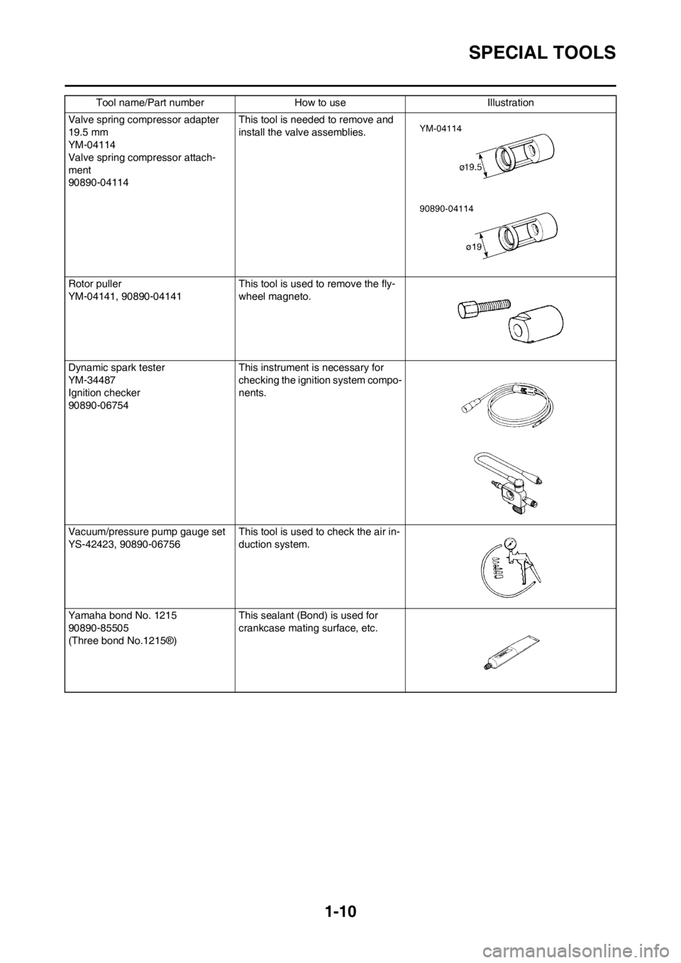
Valve spring compressor adapter
19.5 mm
YM-04114
Valve spring compressor attach-
ment
90890-04114This tool is needed to remove and
install the valve assemblies.
Rotor puller
YM-04141, 90890-04141This tool is used to remove the fly-
wheel magneto.
Dynamic spark tester
YM-34487
Ignition checker
90890-06754This instrument is necessary for
checking the ignition system compo-
nents.
Vacuum/pressure pump gauge set
YS-42423, 90890-06756This tool is used to check the air in-
duction system.
Yamaha bond No. 1215
90890-85505
(Three bond No.1215®)This sealant (Bond) is used for
crankcase mating surface, etc. Tool name/Part number How to use Illustration
Page 34 of 230
2-3
MAINTENANCE SPECIFICATIONS
MAINTENANCE SPECIFICATIONS
ENGINEShock absorber:
Front shock absorber Coil spring/oil damper
Rear shock absorber Coil spring/gas, oil damper
Wheel travel:
Front wheel travel 300 mm (11.81 in)
Rear wheel travel 310 mm (12.20 in)
Electrical:
Ignition system CDI
Generator system AC magneto
Battery type YTZ7S (F)
Battery voltage/capacity 12V/6 AH
Specific gravity 1.31
Headlight type: Quartz bulb (halogen)
Bulb wattage × quantity:
Headlight 12 V 35/36.5 W × 1
Taillight 12 V 1.6/0.3 W × 1
Item Standard Limit
Cylinder head:
Warp limit ---- 0.05 mm (0.002
in)
Cylinder:
Bore size 77.000–77.010 mm (3.0315–3.0319 in) ----
Out of round limit ---- 0.05 mm (0.002
in)
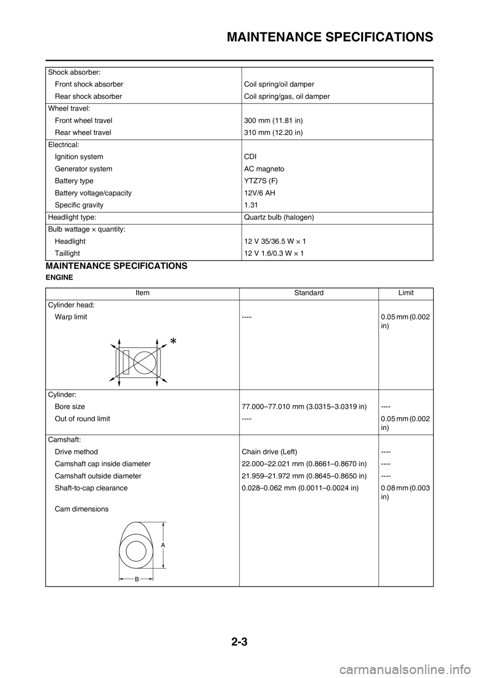
Camshaft:
Drive method Chain drive (Left) ----
Camshaft cap inside diameter 22.000–22.021 mm (0.8661–0.8670 in) ----
Camshaft outside diameter 21.959–21.972 mm (0.8645–0.8650 in) ----
Shaft-to-cap clearance 0.028–0.062 mm (0.0011–0.0024 in) 0.08 mm (0.003
in)
Cam dimensions
Page 41 of 230

2-10
MAINTENANCE SPECIFICATIONS
ELECTRICALFront disc brake:
Disc outside dia.×Thickness 250 × 3.0 mm (9.84 × 0.12 in) 250 × 2.5 mm
(9.84 × 0.10 in)
Pad thickness 4.4 mm (0.17 in) 1.0 mm (0.04
in)
Master cylinder inside dia. 11.00 mm (0.43 in) ----
Caliper cylinder inside dia.27.00 mm (1.06 in) × 2 ----
Brake fluid type DOT #4 ----
Rear disc brake:
Disc outside dia.×Thickness 245 × 4.0 mm (9.65 × 0.16 in) 245 × 3.5 mm
(9.65 × 0.14 in)
Deflection limit ---- 0.15 mm
(0.006 in)
Pad thickness 6.4 mm (0.25 in) 1.0 mm (0.04
in)
Master cylinder inside dia. 11.0 mm (0.43 in) ----
Caliper cylinder inside dia.25.40 mm (1.00 in) × 1 ----
Brake fluid type DOT #4 ----
Brake lever and brake pedal:
Brake lever position 95 mm (3.74 in) ----
Brake pedal height (vertical height above footrest
top)10.0 mm (0.39 in) ----
Clutch lever free play (lever end) 8.0–13.0 mm (0.31–0.51 in) ----
Throttle grip free play 3.0–5.0 mm (0.12–0.20 in) ---- Item Standard Limit
Item Standard Limit
Ignition system:
Advancer type Electrical ----
CDI: AUS, NZ, ZA EUROPE
Pickup coil resistance (color) 248–372 Ωat 20 °C (68
°F) (White–Red)←----
CDI unit-model/manufacturer5UM-F1/YAMAHA 5UM-L1/YAMAHA ----
Ignition coil:
Model/manufacturer 5UL-10/DENSO ----
Minimum spark gap 6.0 mm (0.24 in) ----
Primary coil resistance 0.07–0.10 Ωat 20 °C (68 °F) ----
Secondary coil resistance 4.56–6.84 kΩat 20 °C (68 °F) ----
Charging system:
System type AC magneto ----
Model (stator)/manufacturer 5UM 30/YAMAHA ----
Normal output 14.0 V/120 W at 5,000 r/min ----
Charging coil resistance (color) 0.28–0.43 Ω at 20 °C (68 °F) (White–Ground) ----
Lighting coil resistance (color) 0.22–0.33 Ω at 20 °C (68 °F) (Yellow–Ground) ----
Page 54 of 230
2-23
CABLE ROUTING DIAGRAM
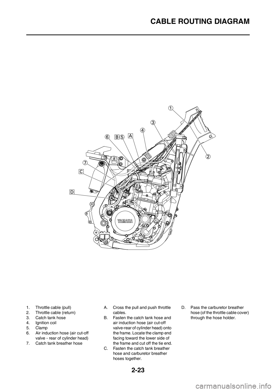
1. Throttle cable (pull)
2. Throttle cable (return)
3. Catch tank hose
4. Ignition coil
5. Clamp
6. Air induction hose (air cut-off
valve - rear of cylinder head)
7. Catch tank breather hoseA. Cross the pull and push throttle
cables.
B. Fasten the catch tank hose and
air induction hose (air cut-off
valve-rear of cylinder head) onto
the frame. Locate the clamp end
facing toward the lower side of
the frame and cut off the tie end.
C. Fasten the catch tank breather
hose and carburetor breather
hoses together.D. Pass the carburetor breather
hose (of the throttle cable cover)
through the hose holder.
Page 64 of 230

3-5
PRE-OPERATION INSPECTION AND MAINTENANCE
PRE-OPERATION INSPECTION AND MAINTENANCE
Before riding for break-in operation or practice, make sure the machine is in good operating condition.
Before using this machine, check the following points.
GENERAL INSPECTION AND MAINTENANCE
Item Routine Page
CoolantCheck that coolant is filled up to the radiator cap. Check the cool-
ing system for leakage.P.3-9 – 10
FuelCheck that a fresh gasoline is filled in the fuel tank. Check the fuel
line for leakage.P.1-18
Engine oilCheck that the oil level is correct. Check the crankcase and oil
line for leakage.P.3-12 – 13
Gear shifter and clutchCheck that gears can be shifted correctly in order and that the
clutch operates smoothly.P.3-10 – 11
Throttle grip/HousingCheck that the throttle grip operation and free play are correctly
adjusted. Lubricate the throttle grip and housing, if necessary.P.3-11
Brakes Check the play of front brake and effect of front and rear brake. P.3-17 – 20
Drive chainCheck drive chain slack and alignment. Check that the drive chain
is lubricated properly.P.3-20 – 21
WheelsCheck for excessive wear and tire pressure. Check for loose
spokes and have no excessive play.P.3-24
SteeringCheck that the handlebar can be turned smoothly and have no ex-
cessive play.P.3-24 – 25
Front forks and rear shock
absorberCheck that they operate smoothly and there is no oil leakage.
P.3-21 – 24
Cables (wires)Check that the clutch and throttle cables move smoothly. Check
that they are not caught when the handlebars are turned or when
the front forks travel up and down.—
Exhaust pipe Check that the exhaust pipe is tightly mounted and has no cracks. P.3-8 – 9
Rear wheel sprocket Check that the rear wheel sprocket tightening bolt is not loose. P.3-20
Lubrication Check for smooth operation. Lubricate if necessary. P.3-26
Bolts and nuts Check the chassis and engine for loose bolts and nuts. P.1-20
Lead connectorsCheck that the AC magneto, CDI unit, and ignition coil are con-
nected tightly.P.1-6
SettingsIs the machine set suitably for the condition of the course and
weather or by taking into account the results of test runs before
riding? Are inspection and maintenance completely done?P.4-1 – 10
Page 73 of 230
3-14
ENGINE
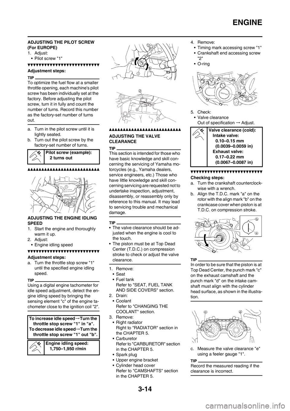
ADJUSTING THE PILOT SCREW
(For EUROPE)
1. Adjust:
• Pilot screw "1"
Adjustment steps:
To optimize the fuel flow at a smaller
throttle opening, each machine's pilot
screw has been individually set at the
factory. Before adjusting the pilot
screw, turn it in fully and count the
number of turns. Record this number
as the factory-set number of turns
out.
a. Turn in the pilot screw until it is
lightly seated.
b. Turn out the pilot screw by the
factory-set number of turns.
ADJUSTING THE ENGINE IDLING
SPEED
1. Start the engine and thoroughly
warm it up.
2. Adjust:
• Engine idling speed
Adjustment steps:
a. Turn the throttle stop screw "1"
until the specified engine idling
speed.
Using a digital engine tachometer for
idle speed adjustment, detect the en-
gine idling speed by bringing the
sensing element "c" of the engine ta-
chometer close to the ignition coil "2".
ADJUSTING THE VALVE
CLEARANCE
This section is intended for those who
have basic knowledge and skill con-
cerning the servicing of Yamaha mo-
torcycles (e.g., Yamaha dealers,
service engineers, etc.) Those who
have little knowledge and skill con-
cerning servicing are requested not to
undertake inspection, adjustment,
disassembly, or reassembly only by
reference to this manual. It may lead
to servicing trouble and mechanical
damage.
• The valve clearance should be ad-
justed when the engine is cool to
the touch.
• The piston must be at Top Dead
Center (T.D.C.) on compression
stroke to check or adjust the valve
clearance.
1. Remove:
•Seat
•Fuel tank
Refer to "SEAT, FUEL TANK
AND SIDE COVERS" section.
2. Drain:
• Coolant
Refer to "CHANGING THE
COOLANT" section.
3. Remove:
• Right radiator
Right to "RADIATOR" section in
the CHAPTER 5.
• Carburetor
Refer to "CARBURETOR" section
in the CHAPTER 5.
• Spark plug
• Upper engine bracket
• Cylinder head cover
Refer to "CAMSHAFTS" section
in the CHAPTER 5.4. Remove:
• Timing mark accessing screw "1"
• Crankshaft end accessing screw
"2"
• O-ring
5. Check:
• Valve clearance
Out of specification→Adjust.
Checking steps:
a. Turn the crankshaft counterclock-
wise with a wrench.
b. Align the T.D.C. mark "a" on the
rotor with the align mark "b" on the
crankcase cover when piston is at
T.D.C. on compression stroke.
In order to be sure that the piston is at
Top Dead Center, the punch mark "c"
on the exhaust camshaft and the
punch mark "d" on the intake cam-
shaft must align with the cylinder
head surface, as shown in the illustra-
tion.
c. Measure the valve clearance "e"
using a feeler gauge "1".
Record the measured reading if the
clearance is incorrect.
Pilot screw (example):
2 turns out
To increase idle speed→Turn the
throttle stop screw "1" in "a".
To decrease idle speed→Turn the
throttle stop screw "1" out "b".
Engine idling speed:
1,750–1,950 r/min
Valve clearance (cold):
Intake valve:
0.10–0.15 mm
(0.0039–0.0059 in)
Exhaust valve:
0.17–0.22 mm
(0.0067–0.0087 in)
Page 86 of 230
3-27
ELECTRICAL
ELECTRICAL
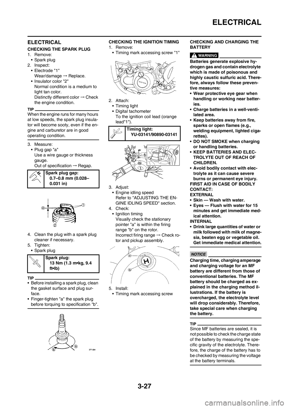
CHECKING THE SPARK PLUG
1. Remove:
• Spark plug
2. Inspect:
• Electrode "1"
Wear/damage→Replace.
• Insulator color "2"
Normal condition is a medium to
light tan color.
Distinctly different color→Check
the engine condition.
When the engine runs for many hours
at low speeds, the spark plug insula-
tor will become sooty, even if the en-
gine and carburetor are in good
operating condition.
3. Measure:
• Plug gap "a"
Use a wire gauge or thickness
gauge.
Out of specification→Regap.
4. Clean the plug with a spark plug
cleaner if necessary.
5. Tighten:
• Spark plug
• Before installing a spark plug, clean
the gasket surface and plug sur-
face.
• Finger-tighten "a" the spark plug
before torquing to specification "b".
CHECKING THE IGNITION TIMING
1. Remove:
• Timing mark accessing screw "1"
2. Attach:
• Timing light
• Digital tachometer
To the ignition coil lead (orange
lead"1").
3. Adjust:
• Engine idling speed
Refer to "ADJUSTING THE EN-
GINE IDLING SPEED" section.
4. Check:
• Ignition timing
Visually check the stationary
pointer "a" is within the firing
range "b" on the rotor.
Incorrect firing range→Check ro-
tor and pickup assembly.
5. Install:
• Timing mark accessing screwCHECKING AND CHARGING THE
BATTERY
Batteries generate explosive hy-
drogen gas and contain electrolyte
which is made of poisonous and
highly caustic sulfuric acid. There-
fore, always follow these preven-
tive measures:
• Wear protective eye gear when
handling or working near batter-
ies.
• Charge batteries in a well-venti-
lated area.
• Keep batteries away from fire,
sparks or open flames (e.g.,
welding equipment, lighted ciga-
rettes).
• DO NOT SMOKE when charging
or handling batteries.
• KEEP BATTERIES AND ELEC-
TROLYTE OUT OF REACH OF
CHILDREN.
• Avoid bodily contact with elec-
trolyte as it can cause severe
burns or permanent eye injury.
FIRST AID IN CASE OF BODILY
CONTACT:
EXTERNAL
• Skin — Wash with water.
• Eyes — Flush with water for 15
minutes and get immediate med-
ical attention.
INTERNAL
• Drink large quantities of water or
milk followed with milk of magne-
sia, beaten egg or vegetable oil.
Get immediate medical attention.
Charging time, charging amperage
and charging voltage for an MF
battery are different from those of
conventional batteries. The MF
battery should be charged as ex-
plained in the charging method il-
lustrations. If the battery is
overcharged, the electrolyte level
will drop considerably. Therefore,
take special care when charging
the battery.
Since MF batteries are sealed, it is
not possible to check the charge state
of the battery by measuring the spe-
cific gravity of the electrolyte. There-
fore, the charge of the battery has to
be checked by measuring the voltage
at the battery terminals.
Spark plug gap:
0.7–0.8 mm (0.028–
0.031 in)
Spark plug:
13 Nm (1.3 m•kg, 9.4
ft•lb)
Timing light:
YU-03141/90890-03141
Page 155 of 230
5-54
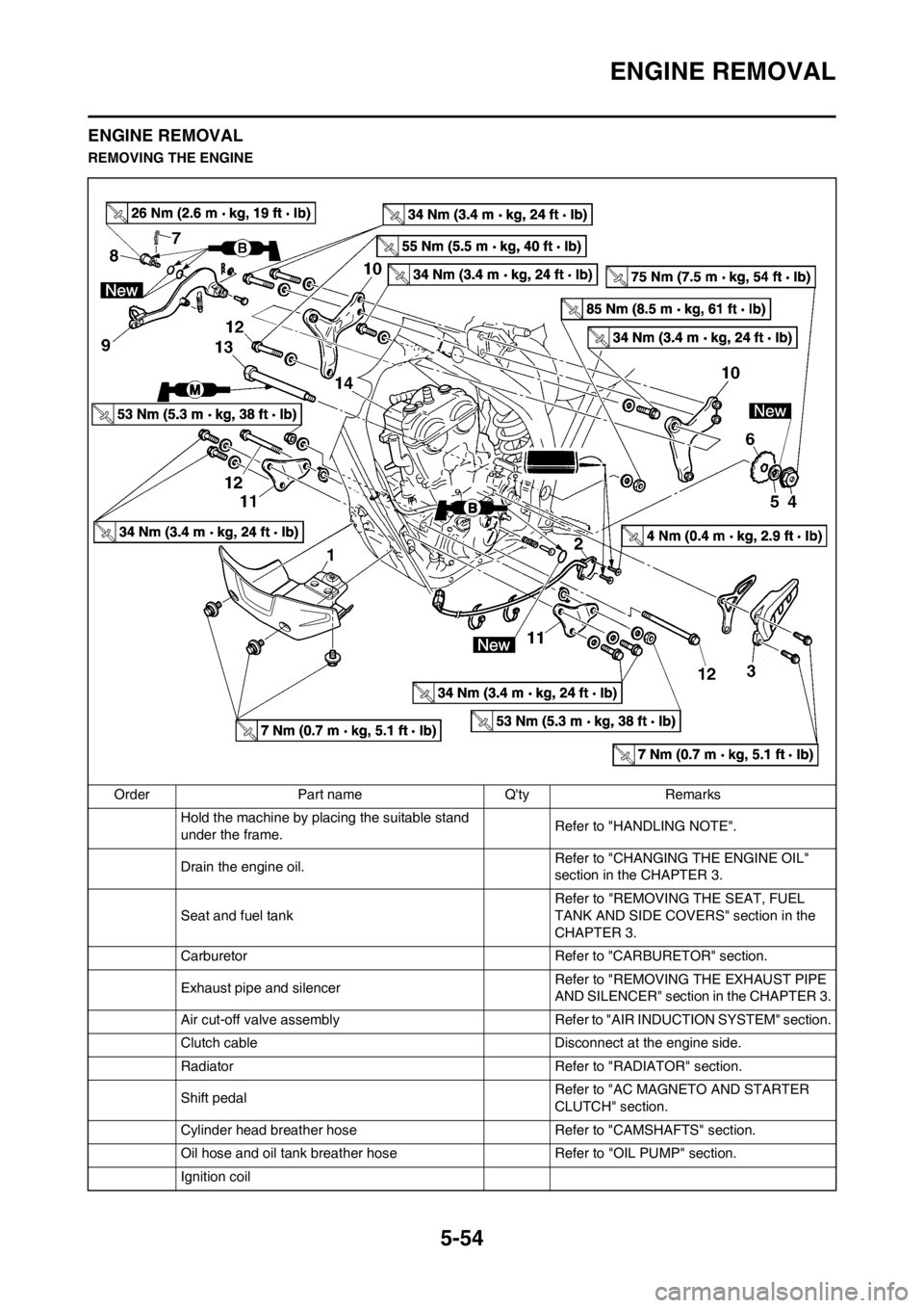
ENGINE REMOVAL
ENGINE REMOVAL
REMOVING THE ENGINE
Order Part name Q'ty Remarks
Hold the machine by placing the suitable stand
under the frame.Refer to "HANDLING NOTE".
Drain the engine oil.Refer to "CHANGING THE ENGINE OIL"
section in the CHAPTER 3.
Seat and fuel tank Refer to "REMOVING THE SEAT, FUEL
TANK AND SIDE COVERS" section in the
CHAPTER 3.
Carburetor Refer to "CARBURETOR" section.
Exhaust pipe and silencer Refer to "REMOVING THE EXHAUST PIPE
AND SILENCER" section in the CHAPTER 3.
Air cut-off valve assembly Refer to "AIR INDUCTION SYSTEM" section.
Clutch cable Disconnect at the engine side.
Radiator Refer to "RADIATOR" section.
Shift pedalRefer to "AC MAGNETO AND STARTER
CLUTCH" section.
Cylinder head breather hose Refer to "CAMSHAFTS" section.
Oil hose and oil tank breather hose Refer to "OIL PUMP" section.
Ignition coil