fuel tank removal YAMAHA WR 250F 2015 Owners Manual
[x] Cancel search | Manufacturer: YAMAHA, Model Year: 2015, Model line: WR 250F, Model: YAMAHA WR 250F 2015Pages: 430, PDF Size: 14.14 MB
Page 119 of 430
ENGINE
3-15
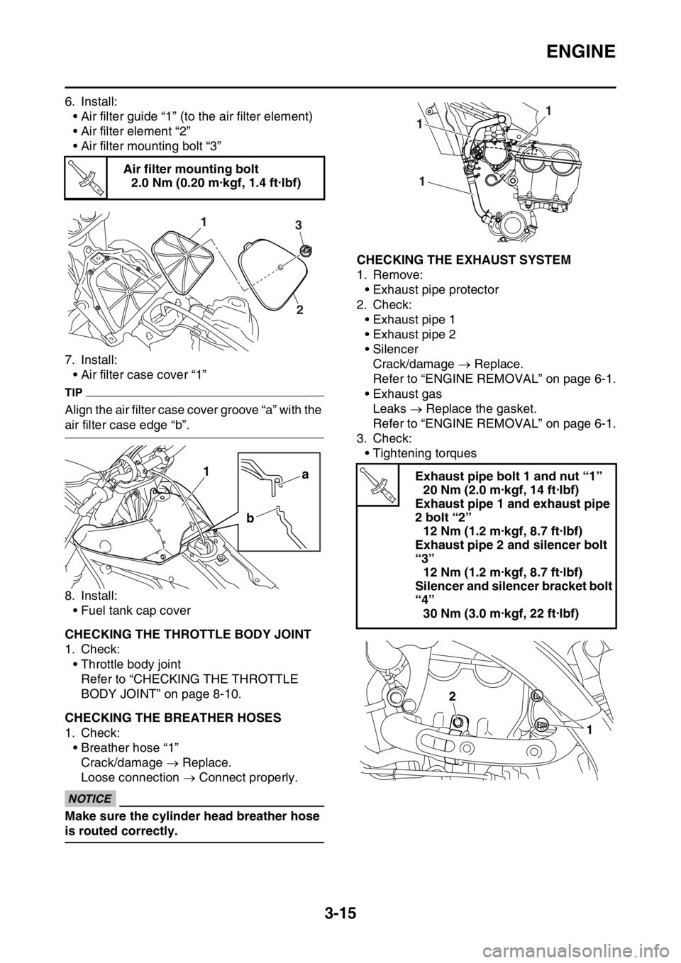
6. Install:
• Air filter guide “1” (to the air filter element)
• Air filter element “2”
• Air filter mounting bolt “3”
7. Install:
• Air filter case cover “1”
TIP
Align the air filter case cover groove “a” with the
air filter case edge “b”.
8. Install:
• Fuel tank cap cover
EAS2GB2094CHECKING THE THROTTLE BODY JOINT
1. Check:
• Throttle body joint
Refer to “CHECKING THE THROTTLE
BODY JOINT” on page 8-10.
EAS2GB2095CHECKING THE BREATHER HOSES
1. Check:
• Breather hose “1”
Crack/damage Replace.
Loose connection Connect properly.
ECA
NOTICE
Make sure the cylinder head breather hose
is routed correctly.
EAS2GB2096CHECKING THE EXHAUST SYSTEM
1. Remove:
• Exhaust pipe protector
2. Check:
• Exhaust pipe 1
• Exhaust pipe 2
• Silencer
Crack/damage Replace.
Refer to “ENGINE REMOVAL” on page 6-1.
• Exhaust gas
Leaks Replace the gasket.
Refer to “ENGINE REMOVAL” on page 6-1.
3. Check:
• Tightening torques Air filter mounting bolt
2.0 Nm (0.20 m·kgf, 1.4 ft·lbf)
T R..
31
2
a
b 1Exhaust pipe bolt 1 and nut “1”
20 Nm (2.0 m·kgf, 14 ft·lbf)
Exhaust pipe 1 and exhaust pipe
2 bolt “2”
12 Nm (1.2 m·kgf, 8.7 ft·lbf)
Exhaust pipe 2 and silencer bolt
“3”
12 Nm (1.2 m·kgf, 8.7 ft·lbf)
Silencer and silencer bracket bolt
“4”
30 Nm (3.0 m·kgf, 22 ft·lbf)
1
1
1
T R..
2
1
Page 234 of 430
ENGINE REMOVAL
6-3
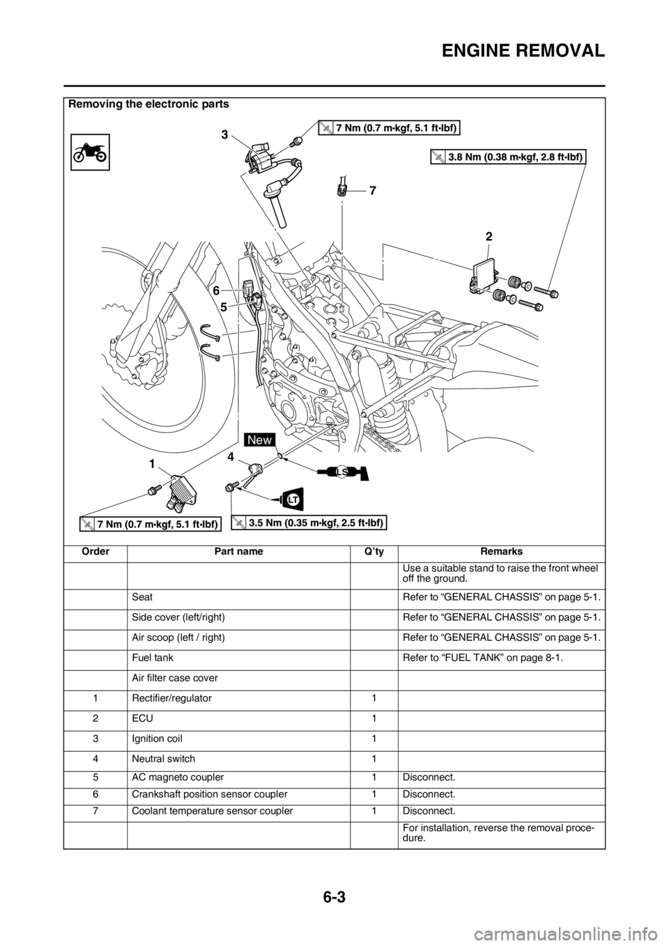
Removing the electronic parts
Order Part name Q’ty Remarks
Use a suitable stand to raise the front wheel
off the ground.
Seat Refer to “GENERAL CHASSIS” on page 5-1.
Side cover (left/right) Refer to “GENERAL CHASSIS” on page 5-1.
Air scoop (left / right) Refer to “GENERAL CHASSIS” on page 5-1.
Fuel tank Refer to “FUEL TANK” on page 8-1.
Air filter case cover
1 Rectifier/regulator 1
2ECU 1
3 Ignition coil 1
4 Neutral switch 1
5 AC magneto coupler 1 Disconnect.
6 Crankshaft position sensor coupler 1 Disconnect.
7 Coolant temperature sensor coupler 1 Disconnect.
For installation, reverse the removal proce-
dure.
T.R.
T.R.
T.R.T.R.
7 3
6
5
142
LT
New
LS
Page 235 of 430
ENGINE REMOVAL
6-4
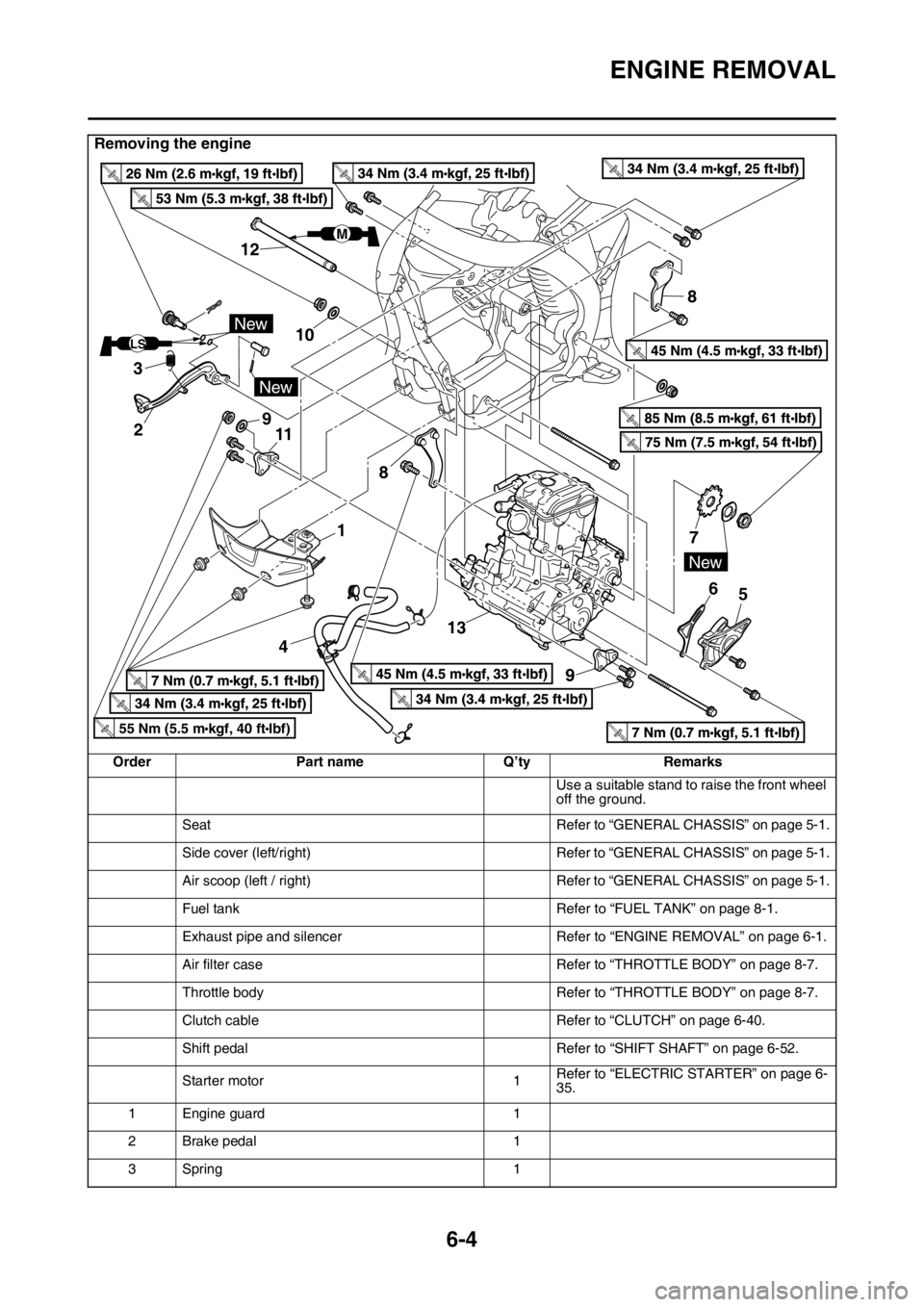
Removing the engine
Order Part name Q’ty Remarks
Use a suitable stand to raise the front wheel
off the ground.
Seat Refer to “GENERAL CHASSIS” on page 5-1.
Side cover (left/right) Refer to “GENERAL CHASSIS” on page 5-1.
Air scoop (left / right) Refer to “GENERAL CHASSIS” on page 5-1.
Fuel tank Refer to “FUEL TANK” on page 8-1.
Exhaust pipe and silencer Refer to “ENGINE REMOVAL” on page 6-1.
Air filter case Refer to “THROTTLE BODY” on page 8-7.
Throttle body Refer to “THROTTLE BODY” on page 8-7.
Clutch cable Refer to “CLUTCH” on page 6-40.
Shift pedal Refer to “SHIFT SHAFT” on page 6-52.
Starter motor 1Refer to “ELECTRIC STARTER” on page 6-
35.
1 Engine guard 1
2 Brake pedal 1
3Spring 1
New
New
LS
M
8
8
7
6
13
45
New
1 12
3
2
1110
9
55 Nm (5.5 m kgf, 40 ft Ibf)T.R.
Page 242 of 430
CAMSHAFT
6-11
EAS2GB2239
CAMSHAFT
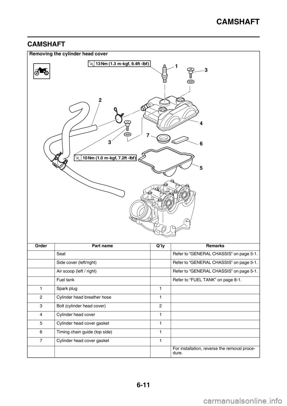
Removing the cylinder head cover
Order Part name Q’ty Remarks
Seat Refer to “GENERAL CHASSIS” on page 5-1.
Side cover (left/right) Refer to “GENERAL CHASSIS” on page 5-1.
Air scoop (left / right) Refer to “GENERAL CHASSIS” on page 5-1.
Fuel tank Refer to “FUEL TANK” on page 8-1.
1 Spark plug 1
2 Cylinder head breather hose 1
3 Bolt (cylinder head cover) 2
4 Cylinder head cover 1
5 Cylinder head cover gasket 1
6 Timing chain guide (top side) 1
7 Cylinder head cover gasket 1
For installation, reverse the removal proce-
dure.
1
4
6 7
5 2
3
10 Nm (1.0 m kgf, 7.2 ft Ibf )T.R.
13 Nm (1.3 m kgf, 9.4 ft Ibf )T.R.
3
Page 249 of 430
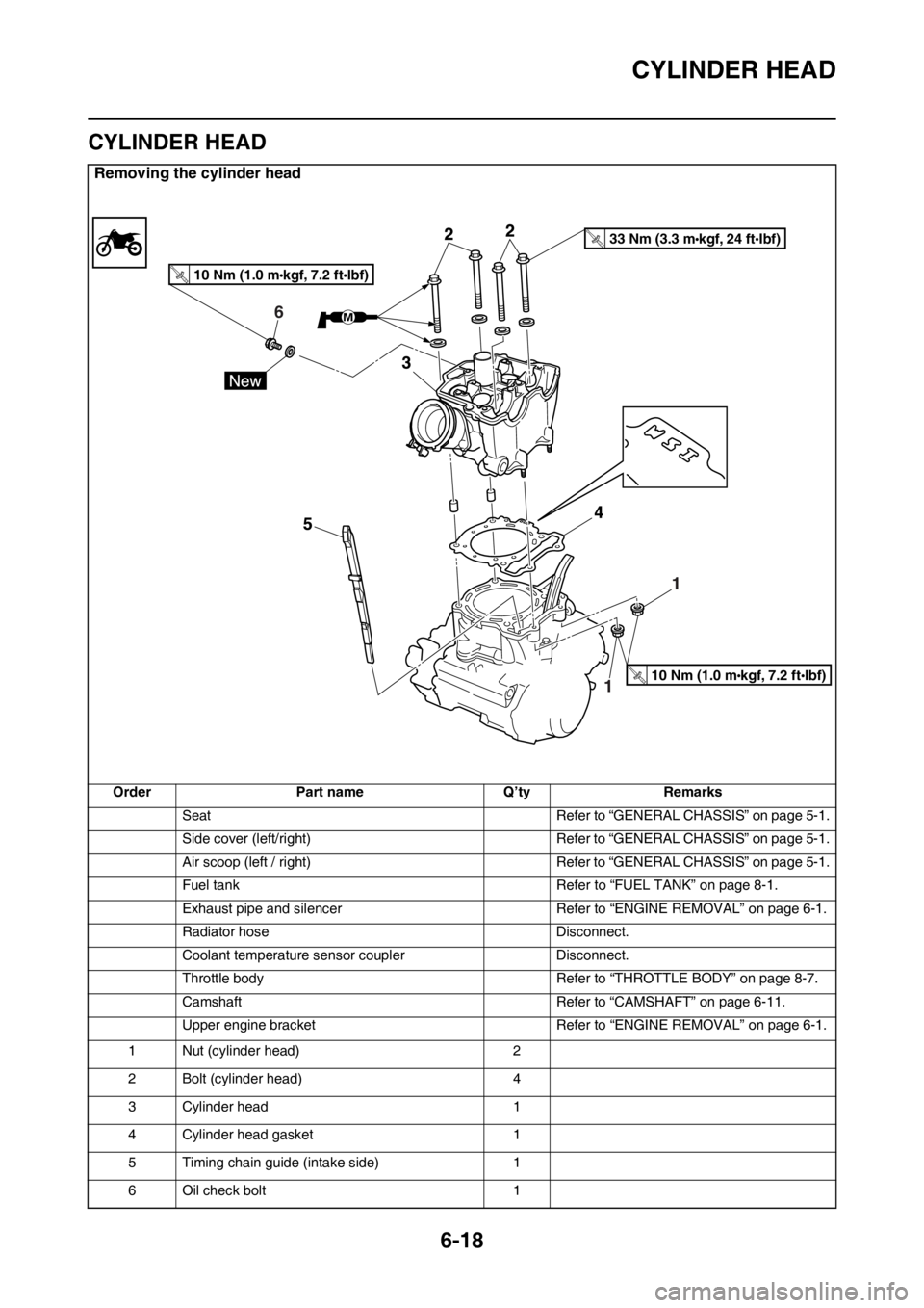
CYLINDER HEAD
6-18
EAS2GB2246
CYLINDER HEAD
Removing the cylinder head
Order Part name Q’ty Remarks
Seat Refer to “GENERAL CHASSIS” on page 5-1.
Side cover (left/right) Refer to “GENERAL CHASSIS” on page 5-1.
Air scoop (left / right) Refer to “GENERAL CHASSIS” on page 5-1.
Fuel tank Refer to “FUEL TANK” on page 8-1.
Exhaust pipe and silencer Refer to “ENGINE REMOVAL” on page 6-1.
Radiator hose Disconnect.
Coolant temperature sensor coupler Disconnect.
Throttle body Refer to “THROTTLE BODY” on page 8-7.
Camshaft Refer to “CAMSHAFT” on page 6-11.
Upper engine bracket Refer to “ENGINE REMOVAL” on page 6-1.
1 Nut (cylinder head) 2
2 Bolt (cylinder head) 4
3 Cylinder head 1
4 Cylinder head gasket 1
5 Timing chain guide (intake side) 1
6 Oil check bolt 1
6
10 Nm (1.0 m kgf, 7.2 ft Ibf)T.R.
33 Nm (3.3 m kgf, 24 ft Ibf)T.R.
10 Nm (1.0 m kgf, 7.2 ft Ibf)T.R.
Page 323 of 430
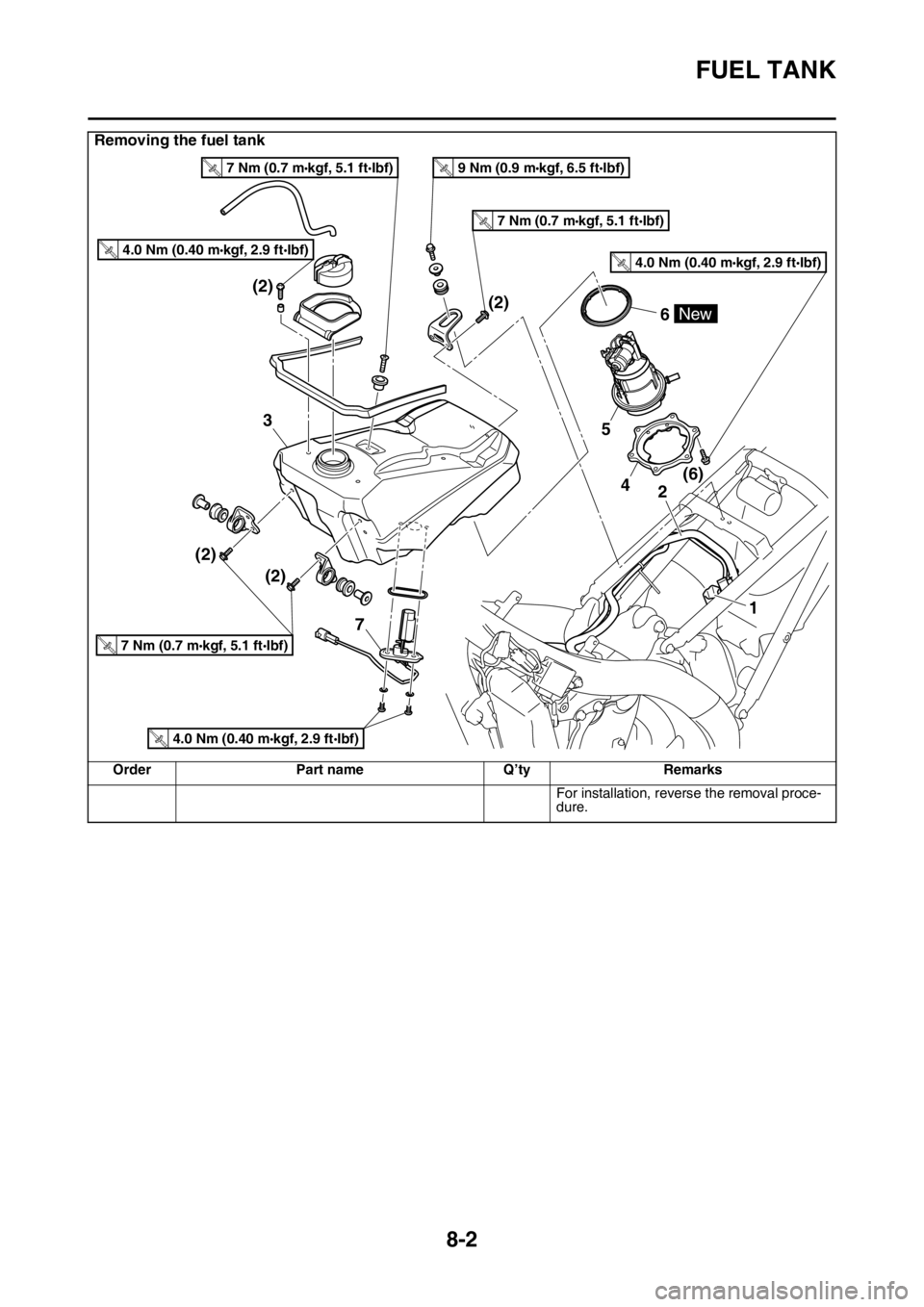
FUEL TANK
8-2
For installation, reverse the removal proce-
dure.
Removing the fuel tank
Order Part name Q’ty Remarks
4(6) (2)
(2) (2)(2)2
5
6
3
1
New
4.0 Nm (0.40 m kgf, 2.9 ft Ibf)T.R.
7 Nm (0.7 m kgf, 5.1 ft Ibf)T.R.
7 Nm (0.7 m kgf, 5.1 ft Ibf)T.R.
7 Nm (0.7 m kgf, 5.1 ft Ibf)T.R.
9 Nm (0.9 m kgf, 6.5 ft Ibf)T.R.
4.0 Nm (0.40 m kgf, 2.9 ft Ibf)T.R.
4.0 Nm (0.40 m kgf, 2.9 ft Ibf)T.R.
7
Page 328 of 430
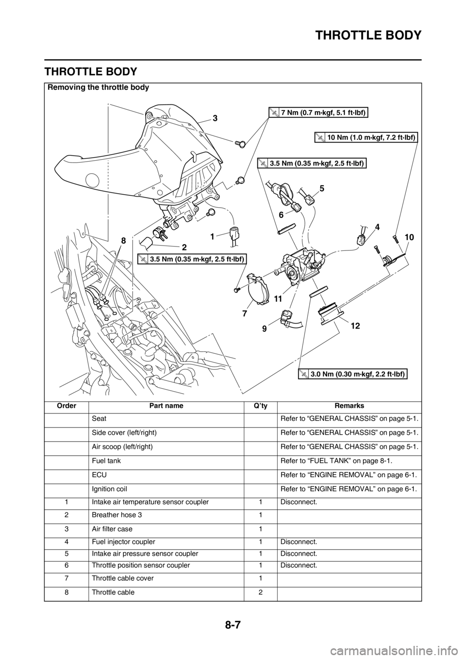
THROTTLE BODY
8-7
EAS2GB2353
THROTTLE BODY
Removing the throttle body
Order Part name Q’ty Remarks
Seat Refer to “GENERAL CHASSIS” on page 5-1.
Side cover (left/right) Refer to “GENERAL CHASSIS” on page 5-1.
Air scoop (left/right) Refer to “GENERAL CHASSIS” on page 5-1.
Fuel tank Refer to “FUEL TANK” on page 8-1.
ECU Refer to “ENGINE REMOVAL” on page 6-1.
Ignition coil Refer to “ENGINE REMOVAL” on page 6-1.
1 Intake air temperature sensor coupler 1 Disconnect.
2 Breather hose 3 1
3 Air filter case 1
4 Fuel injector coupler 1 Disconnect.
5 Intake air pressure sensor coupler 1 Disconnect.
6 Throttle position sensor coupler 1 Disconnect.
7 Throttle cable cover 1
8 Throttle cable 2
3
1
2
7
11
12
10
9
4
8
6
5
3.5 Nm (0.35 m kgf, 2.5 ft Ibf)T.R.
3.5 Nm (0.35 m kgf, 2.5 ft Ibf)T.R.
7 Nm (0.7 m kgf, 5.1 ft Ibf)T.R.
3.0 Nm (0.30 m kgf, 2.2 ft Ibf)T.R.
10 Nm (1.0 m kgf, 7.2 ft Ibf)T.R.