recommended oil YAMAHA WR 250F 2015 Owners Manual
[x] Cancel search | Manufacturer: YAMAHA, Model Year: 2015, Model line: WR 250F, Model: YAMAHA WR 250F 2015Pages: 430, PDF Size: 14.14 MB
Page 23 of 430
IMPORTANT INFORMATION
1-9
EAS20180
IMPORTANT INFORMATION
EAS2GB2022PREPARATION FOR REMOVAL AND DIS-
ASSEMBLY
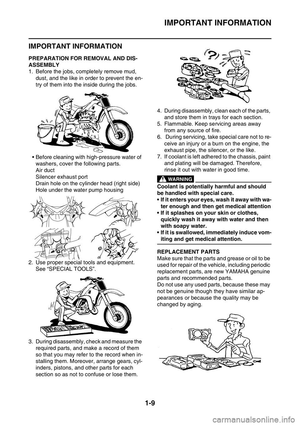
1. Before the jobs, completely remove mud,
dust, and the like in order to prevent the en-
try of them into the inside during the jobs.
• Before cleaning with high-pressure water of
washers, cover the following parts.
Air duct
Silencer exhaust port
Drain hole on the cylinder head (right side)
Hole under the water pump housing
2. Use proper special tools and equipment.
See “SPECIAL TOOLS”.
3. During disassembly, check and measure the
required parts, and make a record of them
so that you may refer to the record when in-
stalling them. Moreover, arrange gears, cyl-
inders, pistons, and other parts for each
section so as not to confuse or lose them.4. During disassembly, clean each of the parts,
and store them in trays for each section.
5. Flammable. Keep servicing areas away
from any source of fire.
6. During servicing, take special care not to re-
ceive an injury or a burn on the engine, the
exhaust pipe, the silencer, or the like.
7. If coolant is left adhered to the chassis, paint
and plating will be damaged. Therefore,
rinse it out with water in good time.
EWA
WARNING
Coolant is potentially harmful and should
be handled with special care.
• If it enters your eyes, wash it away with wa-
ter enough and then get medical attention
• If it splashes on your skin or clothes,
quickly wash it away with water and then
with soapy water.
• If it is swallowed, immediately induce vom-
iting and get medical attention.
EAS2GB2023REPLACEMENT PARTS
Make sure that the parts and grease or oil to be
used for repair of the vehicle, including periodic
replacement parts, are new YAMAHA genuine
parts and recommended parts.
Do not use any used parts, because these may
not be genuine though they have similar ap-
pearances or because the quality may be
changed by aging.
Page 46 of 430
STARTING AND BREAK-IN
1-32
EAS2GB2050
STARTING AND BREAK-IN
EAS2GB2051FUEL
Always use the recommended fuel as stated
below. Also, be sure to use new gasoline the
day of a race.
ECA
NOTICE
Use only unleaded gasoline. The use of
leaded gasoline will cause severe damage
to the engine internal parts such as valves,
piston rings, and exhaust system, etc.
TIP
Your Yamaha engine has been designed to use
premium unleaded gasoline with a pump oc-
tane number [(R+M)/2] of 91 or higher, or a re-
search octane number of 95 or higher. If
knocking (or pinging) occurs, use a gasoline of
a different brand.
EWA
WARNING
• For refueling, be sure to stop the engine
and use enough care not to spill any fuel.
Also be sure to avoid refueling close to a
fire.
• Refuel after the engine, exhaust pipe, etc.
have cooled off.
Gasohol (For USA and Canada)
There are two types of gasohol: gasohol con-
taining ethanol and that containing methanol.
Gasohol containing ethanol can be used if the
ethanol content does not exceed 10%. Gasohol
containing methanol is not recommended by
Yamaha because it can cause damage to the
fuel system or vehicle performance problems.
EAS2GB2052HANDLING NOTEEWA
WARNING
Never start or run the engine in a closed ar-
ea. The exhaust fumes are poisonous; they
can cause loss of consciousness and death
in a very short time. Always operate the ma-
chine in a well-ventilated area.
ECA
NOTICE
• Unlike a two-stroke engine, this engine
cannot be kick started when the throttle is
open because the kickstarter may kick
back. Also, if the throttle is open the air/
fuel mixture may be too lean for the engine
to start.
• Before starting the machine, perform the
checks in the pre-operation check list.
EAS2GB2053AIR FILTER MAINTENANCE
According to “CLEANING THE AIR FILTER
ELEMENT” section in the CHAPTER 3, apply
the foam-air-filter oil or its equivalent to the ele-
ment. (Excess oil in the element may adversely
affect engine starting.)
EAS2GB2054STARTING A COLD ENGINEECA
NOTICE
For maximum engine life, never accelerate
hard when the engine is cold!
In order for the ignition circuit cut-off system to
enable starting, one of the following conditions
must be met:
• The transmission is in the neutral position.
• The transmission is in gear with the clutch le-
ver pulled.
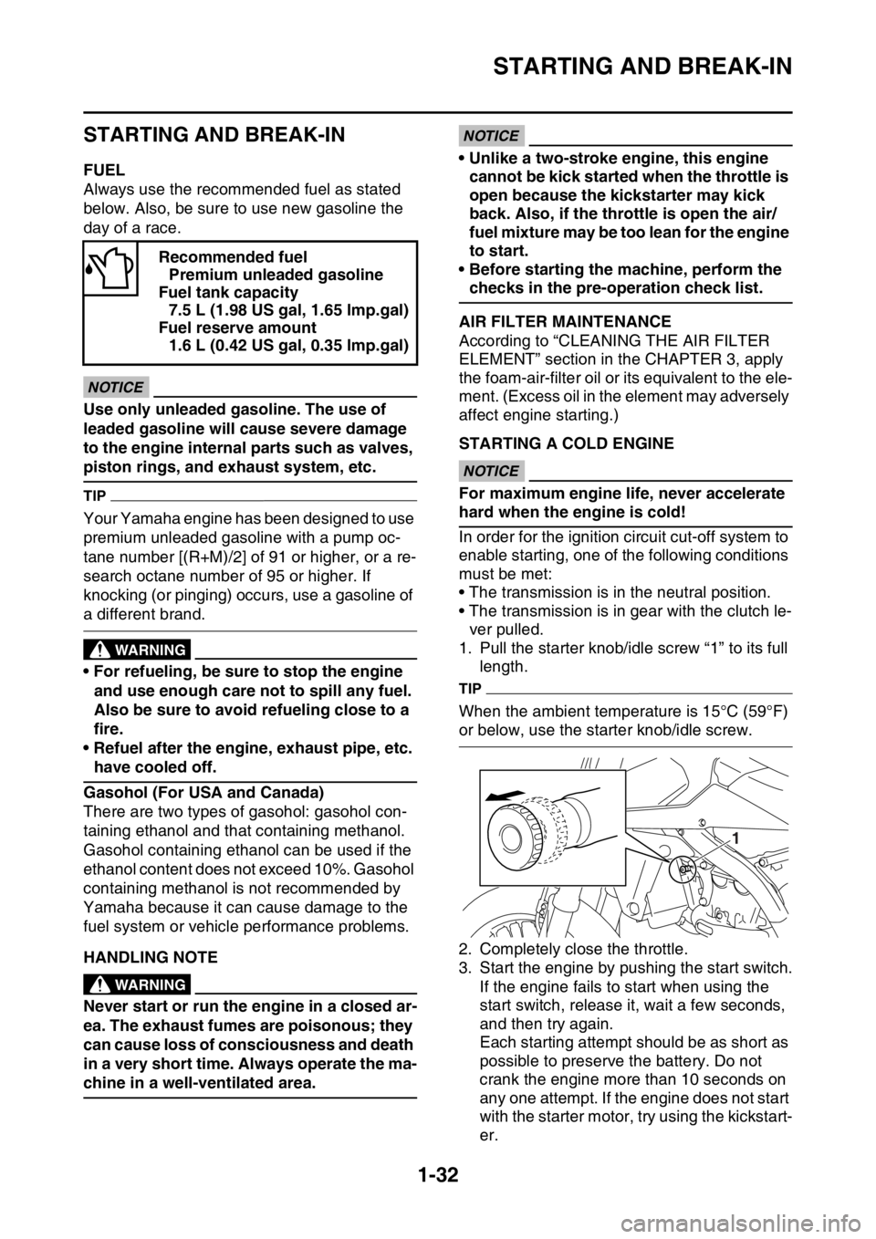
1. Pull the starter knob/idle screw “1” to its full
length.
TIP
When the ambient temperature is 15°C (59°F)
or below, use the starter knob/idle screw.
2. Completely close the throttle.
3. Start the engine by pushing the start switch.
If the engine fails to start when using the
start switch, release it, wait a few seconds,
and then try again.
Each starting attempt should be as short as
possible to preserve the battery. Do not
crank the engine more than 10 seconds on
any one attempt. If the engine does not start
with the starter motor, try using the kickstart-
er. Recommended fuel
Premium unleaded gasoline
Fuel tank capacity
7.5 L (1.98 US gal, 1.65 lmp.gal)
Fuel reserve amount
1.6 L (0.42 US gal, 0.35 lmp.gal)
1
Page 53 of 430
MOTORCYCLE CARE AND STORAGE
1-39
2. Apply a corrosion protection spray on all
metal, including chrome- and nickel-plated,
surfaces to prevent corrosion.
After cleaning
1. Dry the motorcycle with a chamois or an ab-
sorbing cloth.
2. Immediately dry the drive chain and lubri-
cate it to prevent it from rusting.
3. Use a chrome polish to shine chrome, alumi-
num and stainless- steel parts, including the
exhaust system. (Even the thermally in-
duced discoloring of stainless- steel exhaust
systems can be removed through polishing.)
4. To prevent corrosion, it is recommended to
apply a corrosion protection spray on all
metal, including chrome- and nickel-plated,
surfaces.
5. Use spray oil as a universal cleaner to re-
move any remaining dirt.
6. Touch up minor paint damage caused by
stones, etc.
7. Wax all painted surfaces.
8. Let the motorcycle dry completely before
storing or covering it.
EWA
WARNING
Contaminants on the brakes or tires can
cause loss of control.
• Make sure that there is no oil or wax on the
brakes or tires.
• If necessary, clean the brake discs and
brake linings with a regular brake disc
cleaner or acetone, and wash the tires with
warm water and a mild detergent. Before
riding at higher speeds, test the motorcy-
cle’s braking performance and cornering
behavior.
ECA
NOTICE
• Apply spray oil and wax sparingly and
make sure to wipe off any excess.
• Never apply oil or wax to any rubber and
plastic parts, but treat them with a suitable
care product.
• Avoid using abrasive polishing com-
pounds as they will wear away the paint.
TIP
• Consult a Yamaha dealer for advice on what
products to use.
• Washing, rainy weather or humid climates
can cause the headlight lens to fog. Turning
the headlight on for a short period of time will
help remove the moisture from the lens.
EAS2GB2062STORAGE
Short-term
Always store your motorcycle in a cool, dry
place and, if necessary, protect it against dust
with a porous cover. Be sure the engine and the
exhaust system are cool before covering the
motorcycle.
ECA
NOTICE
• Storing the motorcycle in a poorly ventilat-
ed room or covering it with a tarp, while it
is still wet, will allow water and humidity to
seep in and cause rust.
• To prevent corrosion, avoid damp cellars,
stables (because of the presence of am-
monia) and areas where strong chemicals
are stored.
Long-term
Before storing your motorcycle for several
months:
1. Follow all the instructions in the “Care” sec-
tion of this chapter.
2. Fill up the fuel tank and add fuel stabilizer (if
available) to prevent the fuel tank from rust-
ing and the fuel from deteriorating.
3. Perform the following steps to protect the
cylinder, piston rings, etc. from corrosion.
▼▼▼▼▼▼▼▼▼▼▼▼▼▼▼▼▼▼▼▼▼▼▼▼▼▼▼▼▼▼▼▼
a. Remove the spark plug cap and spark plug.
b. Pour a teaspoonful of engine oil into the
spark plug bore.
c. Install the spark plug cap onto the spark
plug, and then place the spark plug on the
cylinder head so that the electrodes are
grounded. (This will limit sparking during the
next step.)
d. Turn the engine over several times with the
starter. (This will coat the cylinder wall with
oil.)
Page 57 of 430

ENGINE SPECIFICATIONS
2-2
EAS2GB2064
ENGINE SPECIFICATIONS
Engine
Engine type Liquid cooled 4-stroke, DOHC
Displacement 250 cm
3
Cylinder arrangement Single cylinder
Bore stroke 77.0 53.6 mm (3.0 2.1 in)
Compression ratio 13.5:1
Starting system Electric starter and kickstarter
Fuel
Recommended fuel Premium unleaded gasoline only
Fuel tank capacity 7.5 L (1.98 US gal, 1.65 Imp.gal)
Fuel reserve amount 1.6 L (0.42 US gal, 0.35 Imp.gal)
Engine oil
Lubrication system Wet sump
Recommended brand YAMALUBE
Type SAE 10W-30, SAE 10W-40, SAE 10W-50,
SAE 15W-40, SAE 20W-40 or SAE 20W-50
Recommended engine oil grade API service SG type or higher, JASO standard
MA
Engine oil quantity
Quantity (disassembled) 1.10 L (1.16 US qt, 0.97 Imp.qt)
Without oil filter element replacement 0.83 L (0.88 US qt, 0.73 Imp.qt)
With oil filter element replacement 0.85 L (0.90 US qt, 0.75 Imp.qt)
Oil filter
Oil filter type Paper
Bypass valve opening pressure 40.0–80.0 kPa (0.40–0.80 kgf/cm
2,
5.8–11.6 psi)
Oil pump
Oil pump type Trochoid
Inner-rotor-to-outer-rotor-tip clearance Less than 0.150 mm (0.0059 in)
Limit 0.20 mm (0.0079 in)
Outer-rotor-to-oil-pump-housing clearance 0.13–0.18 mm (0.0051–0.0071 in)
Limit 0.24 mm (0.0094 in)
Oil-pump-housing-to-inner-and-outer-rotor
clearance 0.06–0.11 mm (0.0024–0.0043 in)
Limit 0.17 mm (0.0067 in)
Cooling system
Radiator capacity (including all routes) 1.00 L (1.06 US qt, 0.88 Imp.qt)
Radiator capacity 0.56 L (0.60 US qt, 0.50 Imp.qt)
Radiator cap opening pressure 107.9–137.3 kPa (1.08–1.37 kg/cm
2,
15.6–19.9 psi)
Radiator core
Width 112.6 mm (4.43 in)
Height 235.0 mm (9.25 in)
Depth 28.0 mm (1.10 in)
Water pump
Water pump type Single suction centrifugal pump
Spark plug
Manufacturer/model NGK/LMAR8G
Spark plug gap 0.7–0.8 mm (0.028–0.031 in)
Page 64 of 430

CHASSIS SPECIFICATIONS
2-9
Brake pad lining thickness (outer) 4.4 mm (0.17 in)
Limit 1.0 mm (0.04 in)
Master cylinder inside diameter 9.52 mm (0.37 in)
Caliper cylinder inside diameter 22.65 mm 2 (0.89 in 2)
Recommended brake fluid DOT 4
Rear brake
Type Single disc brake
Operation Right foot operation
Rear disc brake
Disc outside diameter thickness 245 4.0 mm (9.6 0.16 in)
Brake disc thickness limit 3.5 mm (0.14 in)
Brake disc runout limit (as measured on wheel) 0.15 mm (0.0059 in)
Brake pad lining thickness (inner) 6.4 mm (0.25 in)
Limit 1.0 mm (0.04 in)
Brake pad lining thickness (outer) 6.4 mm (0.25 in)
Limit 1.0 mm (0.04 in)
Master cylinder inside diameter 11.0 mm (0.43 in)
Caliper cylinder inside diameter 25.40 mm 1 (1.00 in 1)
Recommended brake fluid DOT 4
Steering
Steering bearing type Taper roller bearing
Center to lock angle (left) 43.0 °
Center to lock angle (right) 43.0 °
Front suspension
Type Telescopic fork
Spring/shock absorber type Coil spring/oil damper
Front fork travel 310.0 mm (12.20 in)
Fork spring free length 470.0 mm (18.50 in)
Limit 465.0 mm (18.31 in)
Fork spring installed length 470.0 mm (18.50 in)
Spring rate K1 4.40 N/mm (0.45 kgf/mm, 25.12 lbf/in)
Spring stroke K1 0.0–310.0 mm (0.00–12.20 in)
Inner tube outer diameter 48 mm (1.9 in)
Inner tube bending limit 0.2 mm (0.01 in)
Optional spring available Yes
Recommended oil Suspension oil S1
Quantity 540.0 cm
3 (18.26 US oz, 19.05 Imp.oz)
Rebound damping adjusting positions
* Position in which the adjuster is turned in finger tight
Minimum 20 click (s) out*
Standard 10 click (s) out*
Maximum Fully turned in
Compression damping adjusting positions
* Position in which the adjuster is turned in finger tight
Minimum 20 click (s) out*
Standard 11 click (s) out*
Maximum (hard) Fully turned in
Page 105 of 430
PERIODIC MAINTENANCE
3-1
EAS2GB2076
PERIODIC MAINTENANCE
EAS2GB2077INTRODUCTION
This chapter includes all information necessary to perform recommended checks and adjustments.
If followed, these preventive maintenance procedures will ensure more reliable vehicle operation, a
longer service life and reduce the need for costly overhaul work. This information applies to vehicles
already in service as well as to new vehicles that are being prepared for sale. All service technicians
should be familiar with this entire chapter.
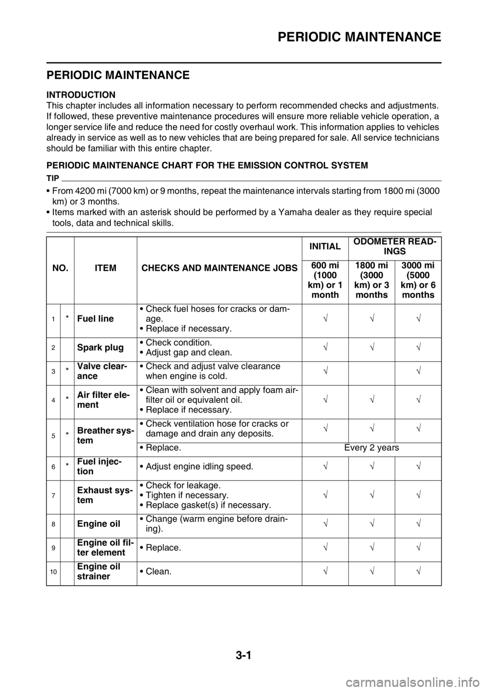
EAS2GB2078PERIODIC MAINTENANCE CHART FOR THE EMISSION CONTROL SYSTEM
TIP
• From 4200 mi (7000 km) or 9 months, repeat the maintenance intervals starting from 1800 mi (3000
km) or 3 months.
• Items marked with an asterisk should be performed by a Yamaha dealer as they require special
tools, data and technical skills.
NO. ITEM CHECKS AND MAINTENANCE JOBSINITIALODOMETER READ-
INGS
600 mi
(1000
km) or 1
month1800 mi
(3000
km) or 3
months3000 mi
(5000
km) or 6
months
1*Fuel line• Check fuel hoses for cracks or dam-
age.
• Replace if necessary.
2Spark plug• Check condition.
• Adjust gap and clean.
3*Valve clear-
ance• Check and adjust valve clearance
when engine is cold.
4*Air filter ele-
ment• Clean with solvent and apply foam air-
filter oil or equivalent oil.
• Replace if necessary.
5*Breather sys-
tem• Check ventilation hose for cracks or
damage and drain any deposits.
• Replace. Every 2 years
6*Fuel injec-
tion• Adjust engine idling speed.
7Exhaust sys-
tem• Check for leakage.
• Tighten if necessary.
• Replace gasket(s) if necessary.
8Engine oil• Change (warm engine before drain-
ing).
9Engine oil fil-
ter element• Replace.
10Engine oil
strainer• Clean.
Page 108 of 430
PERIODIC MAINTENANCE
3-4
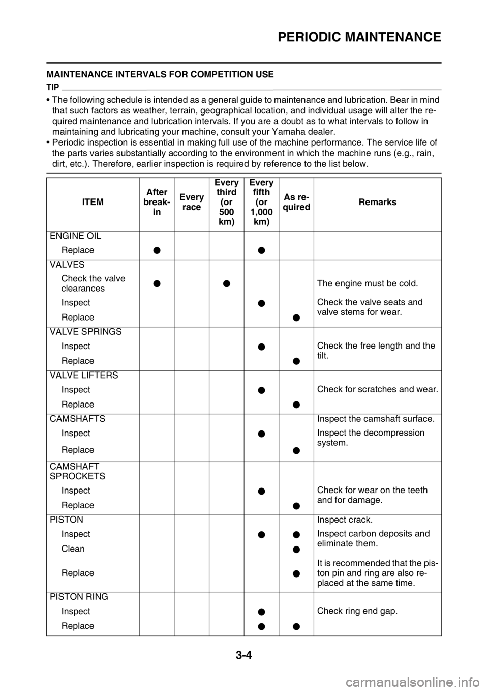
EAS2GB2080MAINTENANCE INTERVALS FOR COMPETITION USE
TIP
• The following schedule is intended as a general guide to maintenance and lubrication. Bear in mind
that such factors as weather, terrain, geographical location, and individual usage will alter the re-
quired maintenance and lubrication intervals. If you are a doubt as to what intervals to follow in
maintaining and lubricating your machine, consult your Yamaha dealer.
• Periodic inspection is essential in making full use of the machine performance. The service life of
the parts varies substantially according to the environment in which the machine runs (e.g., rain,
dirt, etc.). Therefore, earlier inspection is required by reference to the list below.
ITEMAfter
break-
inEvery
raceEvery
third
(or
500
km)Every
fifth
(or
1,000
km)As re-
quiredRemarks
ENGINE OIL
Replace
VALVES
Check the valve
clearancesThe engine must be cold.
InspectCheck the valve seats and
valve stems for wear.
Replace
VALVE SPRINGS
InspectCheck the free length and the
tilt.
Replace
VALVE LIFTERS
InspectCheck for scratches and wear.
Replace
CAMSHAFTS Inspect the camshaft surface.
InspectInspect the decompression
system.
Replace
CAMSHAFT
SPROCKETS
InspectCheck for wear on the teeth
and for damage.
Replace
PISTON Inspect crack.
InspectInspect carbon deposits and
eliminate them.
Clean
ReplaceIt is recommended that the pis-
ton pin and ring are also re-
placed at the same time.
PISTON RING
InspectCheck ring end gap.
Replace
Page 118 of 430
ENGINE
3-14
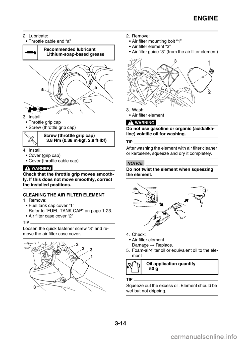
2. Lubricate:
• Throttle cable end “a”
3. Install:
• Throttle grip cap
• Screw (throttle grip cap)
4. Install:
• Cover (grip cap)
• Cover (throttle cable cap)
EWA
WARNING
Check that the throttle grip moves smooth-
ly. If this does not move smoothly, correct
the installed positions.
EAS2GB2093CLEANING THE AIR FILTER ELEMENT
1. Remove:
• Fuel tank cap cover “1”
Refer to “FUEL TANK CAP” on page 1-23.
• Air filter case cover “2”
TIP
Loosen the quick fastener screw “3” and re-
move the air filter case cover.2. Remove:
• Air filter mounting bolt “1”
• Air filter element “2”
• Air filter guide “3” (from the air filter element)
3. Wash:
• Air filter element
EWA
WARNING
Do not use gasoline or organic (acid/alka-
line) volatile oil for washing.
TIP
After washing the element with air filter cleaner
or kerosene, squeeze and dry it completely.
ECA
NOTICE
Do not twist the element when squeezing
the element.
4. Check:
• Air filter element
Damage Replace.
5. Foam-air-filter oil or equivalent oil to the ele-
ment
TIP
Squeeze out the excess oil. Element should be
wet but not dripping. Recommended lubricant
Lithium-soap-based grease
Screw (throttle grip cap)
3.8 Nm (0.38 m·kgf, 2.8 ft·lbf)
T R..
1
2
3
3
3
Oil application quantify
50 g
13
2
Page 120 of 430
ENGINE
3-16
4. Install:
• Exhaust pipe protector
EAS2GB2097CHECKING THE FUEL LINE
1. Remove:
• Seat
• Side cover (left/right)
• Air scoop (left/right)
Refer to “GENERAL CHASSIS” on page 5-
1.
• Fuel tank
Refer to “FUEL TANK” on page 8-1.
2. Check:
• Fuel hose “1”
Crack/damage Replace.
Loose connection Connect properly.
3. Install:
• Fuel tank
Refer to “FUEL TANK” on page 8-1.
• Air scoop (left/right)
• Seat
• Side cover (left/right)
Refer to “GENERAL CHASSIS” on page 5-
1.
EAS2GB2098
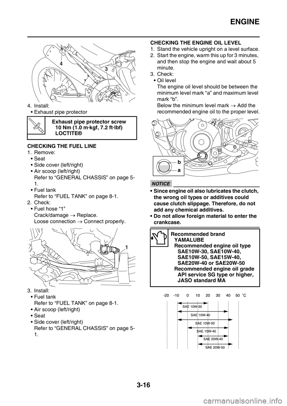
CHECKING THE ENGINE OIL LEVEL
1. Stand the vehicle upright on a level surface.
2. Start the engine, warm this up for 3 minutes,
and then stop the engine and wait about 5
minute.
3. Check:
• Oil level
The engine oil level should be between the
minimum level mark “a” and maximum level
mark “b”.
Below the minimum level mark Add the
recommended engine oil to the proper level.
ECA
NOTICE
• Since engine oil also lubricates the clutch,
the wrong oil types or additives could
cause clutch slippage. Therefore, do not
add any chemical additives.
• Do not allow foreign material to enter the
crankcase. Exhaust pipe protector screw
10 Nm (1.0 m·kgf, 7.2 ft·lbf)
LOCTITE®
4
3
T R..
1
Recommended brand
YAMALUBE
Recommended engine oil type
SAE10W-30, SAE10W-40,
SAE10W-50, SAE15W-40,
SAE20W-40 or SAE20W-50
Recommended engine oil grade
API service SG type or higher,
JASO standard MA
a b
Page 141 of 430
CHASSIS
3-37
c. Turn the front fork to the right and left a few
times, and make sure that the steering ro-
tates smoothly. If it does not turn smoothly,
remove the lower bracket and check the up-
per and lower bearings.
Refer to “STEERING HEAD” on page 5-53.
d. Loosen the ring nut fully turn and then tight-
en it to specification with a steering nut
wrench.
EWA
WARNING
Do not overtighten the lower ring nut.
e. Check the steering head for looseness or
binding by turning the front fork all the way in
both directions. If any binding is felt, remove
the lower bracket and check the upper and
lower bearings.
Refer to “STEERING HEAD” on page 5-53.
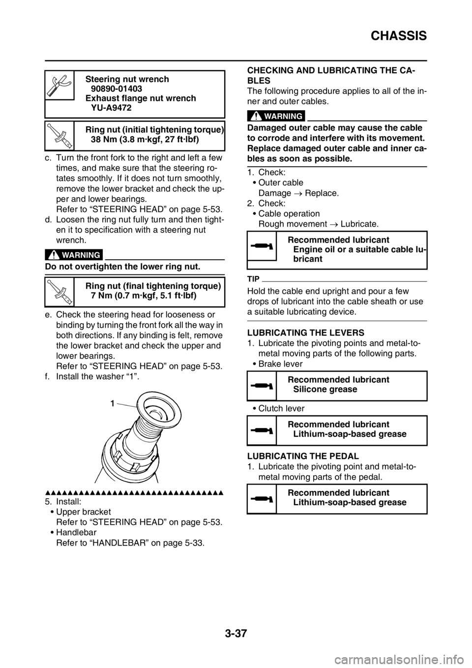
f. Install the washer “1”.
▲▲▲▲▲▲▲▲▲▲▲▲▲▲▲▲▲▲▲▲▲▲▲▲▲▲▲▲▲▲▲▲
5. Install:
• Upper bracket
Refer to “STEERING HEAD” on page 5-53.
• Handlebar
Refer to “HANDLEBAR” on page 5-33.
EAS2GB2126
CHECKING AND LUBRICATING THE CA-
BLES
The following procedure applies to all of the in-
ner and outer cables.
EWA
WARNING
Damaged outer cable may cause the cable
to corrode and interfere with its movement.
Replace damaged outer cable and inner ca-
bles as soon as possible.
1. Check:
• Outer cable
Damage Replace.
2. Check:
• Cable operation
Rough movement Lubricate.
TIP
Hold the cable end upright and pour a few
drops of lubricant into the cable sheath or use
a suitable lubricating device.
EAS2GB2127LUBRICATING THE LEVERS
1. Lubricate the pivoting points and metal-to-
metal moving parts of the following parts.
•Brake lever
• Clutch lever
EAS2GB2128LUBRICATING THE PEDAL
1. Lubricate the pivoting point and metal-to-
metal moving parts of the pedal. Steering nut wrench
90890-01403
Exhaust flange nut wrench
YU-A9472
Ring nut (initial tightening torque)
38 Nm (3.8 m·kgf, 27 ft·lbf)
Ring nut (final tightening torque)
7 Nm (0.7 m·kgf, 5.1 ft·lbf)
T R..
T R..
1
Recommended lubricant
Engine oil or a suitable cable lu-
bricant
Recommended lubricant
Silicone grease
Recommended lubricant
Lithium-soap-based grease
Recommended lubricant
Lithium-soap-based grease