YAMAHA WR 250F 2016 Owners Manual
WR 250F 2016
YAMAHA
YAMAHA
https://www.carmanualsonline.info/img/51/52288/w960_52288-0.png
YAMAHA WR 250F 2016 Owners Manual
Trending: turn signal, oil reset, window, change time, coolant temperature, brake sensor, oil change
Page 341 of 428
ELECTRIC STARTING SYSTEM
9-9
a. WHEN THE TRANSMISSION IS IN NEU-
TRAL
b. WHEN THE CLUTCH LEVER IS PULLED
TO THE HANDLEBAR
1. Battery
2. Main fuse
3. Main relay
4. Starting circuit cut-off relay
5. Start switch
6. Diode
7. Clutch switch
8. Neutral switch
9. Starter relay
10.Starter motor
Page 342 of 428

ELECTRIC STARTING SYSTEM
9-10
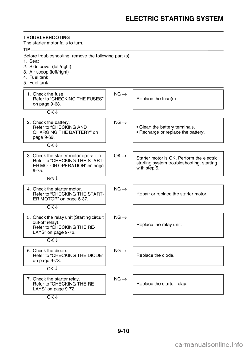
EAS2GB7362TROUBLESHOOTING
The starter motor fails to turn.
TIP
Before troubleshooting, remove the following part (s):
1. Seat
2. Side cover (left/right)
3. Air scoop (left/right)
4. Fuel tank
5. Fuel tank
1. Check the fuse.
Refer to “CHECKING THE FUSES”
on page 9-68.NG
Replace the fuse(s).
OK
2. Check the battery.
Refer to “CHECKING AND
CHARGING THE BATTERY” on
page 9-69.NG
• Clean the battery terminals.
• Recharge or replace the battery.
OK
3. Check the starter motor operation.
Refer to “CHECKING THE START-
ER MOTOR OPERATION” on page
9-75.OK
Starter motor is OK. Perform the electric
starting system troubleshooting, starting
with step 5.
NG
4. Check the starter motor.
Refer to “CHECKING THE START-
ER MOTOR” on page 6-37.NG
Repair or replace the starter motor.
OK
5. Check the relay unit (Starting circuit
cut-off relay).
Refer to “CHECKING THE RE-
LAYS” on page 9-72.NG
Replace the relay unit.
OK
6. Check the diode.
Refer to “CHECKING THE DIODE”
on page 9-73.NG
Replace the diode.
OK
7. Check the starter relay.
Refer to “CHECKING THE RE-
LAYS” on page 9-72.NG
Replace the starter relay.
OK
Page 343 of 428
ELECTRIC STARTING SYSTEM
9-11
8. Check the main relay.
Refer to “CHECKING THE RE-
LAYS” on page 9-72.NG
Replace the main relay.
OK
9. Check the neutral switch.
Refer to “CHECKING THE
SWITCHES” on page 9-64.NG
Replace the neutral switch.
OK
10.Check the clutch switch.
Refer to “CHECKING THE
SWITCHES” on page 9-64.NG
Replace the clutch switch.
OK
11.Check the engine stop switch.
Refer to “CHECKING THE
SWITCHES” on page 9-64.NG
Replace the start switch.
OK
12.Check the start switch.
Refer to “CHECKING THE
SWITCHES” on page 9-64.NG
Replace the engine stop switch.
OK
13.Check the entire starting system’s
wiring.
Refer to “CIRCUIT DIAGRAM” on
page 9-6.NG
Properly connect or repair the starting sys-
tem’s wiring.
OK
Replace the ECU.
Page 344 of 428

CHARGING SYSTEM
9-12
EAS27200
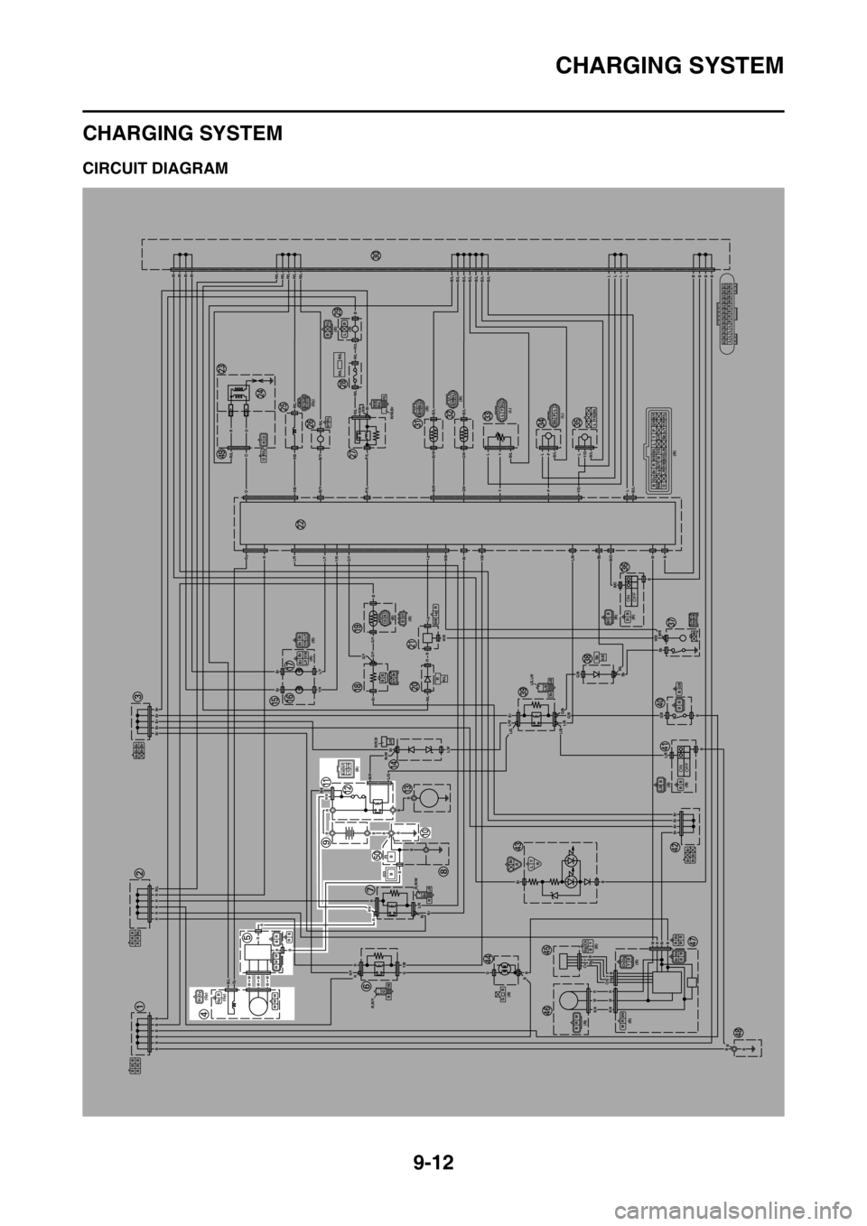
CHARGING SYSTEM
EAS2GB7363CIRCUIT DIAGRAM
ONOFF
ONOFF
BBB
BBB
RRR
RRR/L
Br Br Br
Br Br
(Gy)
(Gy)B/LGyWW WB Gy
B R
WW W
BR
R,R/Y
G
R
Y/B
R,R/W
Br
RL/R
(B)R/YR/WBr/WL/G
Br/W,BrL/W
(B) (B)Br BrL/Y Y/R
G/YBrBB
BrBrL/YY/W
(B)(B)BB GG/Y
RR/L
R Lg
W/B
(B) BGyBr RW/BB/LLYP
G/WB/Y
R/BLgG/YW
Br/W
OL/RY/BB/OL/BSbY/R L/Y P/L
Y/G
(Gy)R/L R/BR/LB/Y
R/WR/L
R/W,BrP/L
R/L R/L
(B)
(B)
(B)
(L)
(L)(B) BR/LLBR/L R/L R/L R/L R/L B/L B/L B/L B/L B/L B/L B/LL L L LBBBB
Br Br Br Br
B/LBr/W
B/LG/WLYB/L
B/LPLB/LY/GL
(B)
(B)B/OBB BSbW/B
Sb
SbG/B
L/G,L/WL/BBrG/BG/BB
BB
(B)
(B)L/BBB B
Br Br
Br BrBr
BB LY
(B)
(B)
(B)
(B)
(B)
GB
Ch Dg
Y B
BRW
Br R
B W
B/WR W
Ch DgYBBrR/WBW
R O
OR/L
B
B
BBBBBB
RRRRRR/L
BrBrBrBrBr
Br
Br
BrBrBrBrR/LR/LR/LR/LR/L
B
LLLP
PL
Y
Y
RR
Br
R/LR/L
R/L
P/L
P/L
R/L
R/L
R/LR/B
R/B
L/RL/Y
L/Y
Y/R
Y/R
G/Y
G/YG/Y
G/Y
B/Y
B/Y
R/LB/LB/L
B/LB/LB/LY/G
Y/GB/L
B/OL/BY/BW/B
W/B
G/B
L/B
W/BW/B
L/BL/BL/GL/W
L/W
L/R
Br/W
Br/W
R/W
R/W
R/Y
R/Y
G/BG/B
G/B
B/O
B/LB/LB/LB/LB/LB/LB/L
G/W
G/W
Br/W
Br/W
R/WR/WBr
O
O
OR
RGy
LLLLBBBB
B
B
B
B
BBB
B
B
RRWW
Y
Y
Dg
Dg
Ch
Ch
RW
BrBrBrBr
Br
B
W
Sb
SbSb
SbBr
Br
B
Br
Lg
Lg
R/L
R
R
RR
Gy
BB
WWWWWW
R
RRGGBB
B
Y/B
RB
BB
B
B
Br
Br
Br
B
L/G
B/L
B/WB/W
B
Page 345 of 428
CHARGING SYSTEM
9-13
4. AC magneto
5. Rectifier/regulator
9. Battery
10.Frame ground
11.Starter relay
12.Main fuse
50.Negative battery lead
Page 346 of 428
CHARGING SYSTEM
9-14
EAS2GB7364TROUBLESHOOTING
The battery is not being charged.
TIP
Before troubleshooting, remove the following part (s):
1. Seat
2. Side cover (left/right)
1. Check the fuse.
Refer to “CHECKING THE FUSES”
on page 9-68.NG
Replace the fuse(s).
OK
2. Check the battery.
Refer to “CHECKING AND
CHARGING THE BATTERY” on
page 9-69.NG
• Clean the battery terminals.
• Recharge or replace the battery.
OK
3. Check the stator coil.
Refer to “CHECKING THE STA-
TOR COIL” on page 9-76.NG
Replace the stator assembly.
OK
4. Check the rectifier/regulator.
Refer to “CHECKING THE RECTI-
FIER/REGULATOR” on page 9-76.NG
Replace the rectifier/regulator.
OK
5. Check the entire charging system’s
wiring.
Refer to “CIRCUIT DIAGRAM” on
page 9-12.NG
Properly connect or repair the charging
system’s wiring.
OK
This circuit is OK.
Page 347 of 428
Page 348 of 428

LIGHTING SYSTEM
9-16
EAS27240
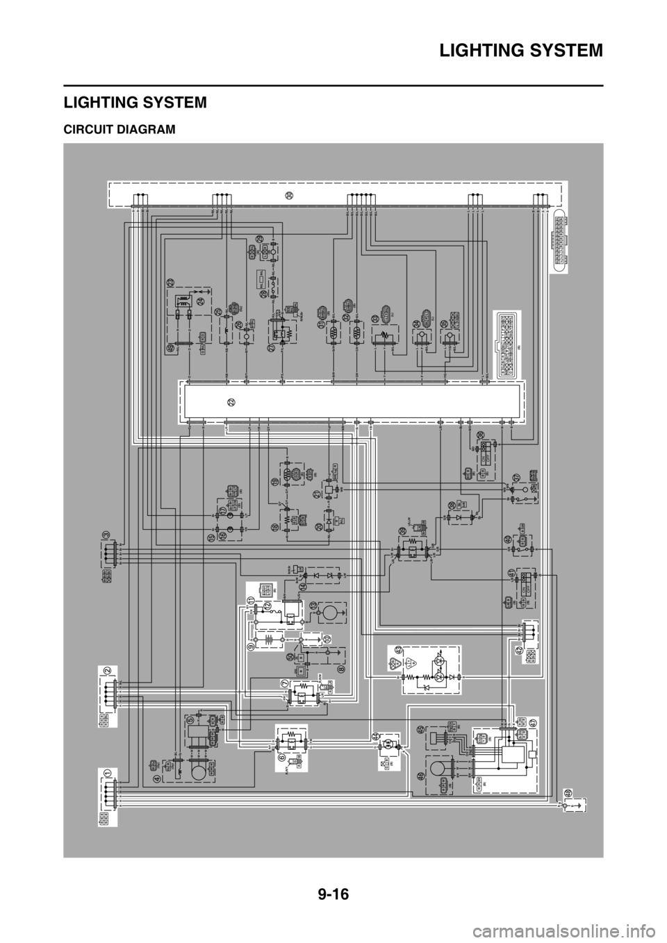
LIGHTING SYSTEM
EAS2GB7365CIRCUIT DIAGRAM
ONOFF
ONOFF
BBB
BBB
RRR
RRR/L
Br Br Br
Br Br
(Gy)
(Gy)B/LGyWW WB Gy
B R
WW W
BR
R,R/Y
G
R
Y/B
R,R/W
Br
RL/R
(B)R/YR/WBr/WL/G
Br/W,BrL/W
(B) (B)Br BrL/Y Y/R
G/YBrBB
BrBrL/YY/W
(B)(B)BB GG/Y
RR/L
R Lg
W/B
(B) BGyBr RW/BB/LLYP
G/WB/Y
R/BLgG/YW
Br/W
OL/RY/BB/OL/BSbY/R L/Y P/L
Y/G
(Gy)R/L R/BR/LB/Y
R/WR/L
R/W,BrP/L
R/L R/L
(B)
(B)
(B)
(L)
(L)(B) BR/LLBR/L R/L R/L R/L R/L B/L B/L B/L B/L B/L B/L B/LL L L LBBBB
Br Br Br Br
B/LBr/W
B/LG/WLYB/L
B/LPLB/LY/GL
(B)
(B)B/OBB BSbW/B
Sb
SbG/B
L/G,L/WL/BBrG/BG/BB
BB
(B)
(B)L/BBB B
Br Br
Br BrBr
BB LY
(B)
(B)
(B)
(B)
(B)
GB
Ch Dg
Y B
BRW
Br R
B W
B/WR W
Ch DgYBBrR/WBW
R O
OR/L
B
B
BBBBBB
RRRRRR/L
BrBrBrBrBr
Br
Br
BrBrBrBrR/LR/LR/LR/LR/L
B
LLLP
PL
Y
Y
RR
Br
R/LR/L
R/L
P/L
P/L
R/L
R/L
R/LR/B
R/B
L/RL/Y
L/Y
Y/R
Y/R
G/Y
G/YG/Y
G/Y
B/Y
B/Y
R/LB/LB/L
B/LB/LB/LY/G
Y/GB/L
B/OL/BY/BW/B
W/B
G/B
L/B
W/BW/B
L/BL/BL/GL/W
L/W
L/R
Br/W
Br/W
R/W
R/W
R/Y
R/Y
G/BG/B
G/B
B/O
B/LB/LB/LB/LB/LB/LB/L
G/W
G/W
Br/W
Br/W
R/WR/WBr
O
O
OR
RGy
LLLLBBBB
B
B
B
B
BBB
B
B
RRWW
Y
Y
Dg
Dg
Ch
Ch
RW
BrBrBrBr
Br
B
W
Sb
SbSb
SbBr
Br
B
Br
Lg
Lg
R/L
R
R
RR
Gy
BB
WWWWWW
R
RRGGBB
B
Y/B
RB
BB
B
B
Br
Br
Br
B
L/G
B/L
B/WB/W
B
Page 349 of 428
LIGHTING SYSTEM
9-17
1. Joint connector
2. Joint connector
6. Headlight relay
7. Main relay
9. Battery
10.Frame ground
11.Starter relay
12.Main fuse
22.ECU (engine control unit)
30.Joint connector
42.Joint connector
43.Taillight
44.Headlight
47.Multi-function display
48.Frame ground
Page 350 of 428

LIGHTING SYSTEM
9-18
EAS2GB7366TROUBLESHOOTING
Any of the following fail to light: headlight or meter light.
TIP
Before troubleshooting, remove the following part (s):
1. Seat
2. Side cover (left)
3. Air scoop (left/right)
4. Fuel tank
1. Check the each bulbs condition.
Refer to “CHECKING THE BULBS
AND BULB SOCKETS” on page 9-
67.NG
Replace the bulb (s).
OK
2. Check the fuse.
Refer to “CHECKING THE FUSES”
on page 9-68.NG
Replace the fuse(s).
OK
3. Check the battery.
Refer to “CHECKING AND
CHARGING THE BATTERY” on
page 9-69.NG
• Clean the battery terminals.
• Recharge or replace the battery.
OK
4. Check the main relay.
Refer to “CHECKING THE RE-
LAYS” on page 9-72.NG
Replace the main relay.
OK
5. Check the headlight relay.
Refer to “CHECKING THE RE-
LAYS” on page 9-72.NG
Replace the headlight relay.
OK
6. Check the entire lighting system’s
wiring.
Refer to “CIRCUIT DIAGRAM” on
page 9-16.NG
Properly connect or repair the lighting sys-
tem’s wiring.
OK
Replace the ECU, meter assembly, or
taillight.
Trending: service schedule, ground clearance, air condition, length, change time, run flat, fuel


