YAMAHA WR 250F 2016 Service Manual
Manufacturer: YAMAHA, Model Year: 2016, Model line: WR 250F, Model: YAMAHA WR 250F 2016Pages: 428, PDF Size: 14.13 MB
Page 41 of 428

MULTI-FUNCTION DISPLAY
1-27
Page 42 of 428
MULTI-FUNCTION DISPLAY
1-28
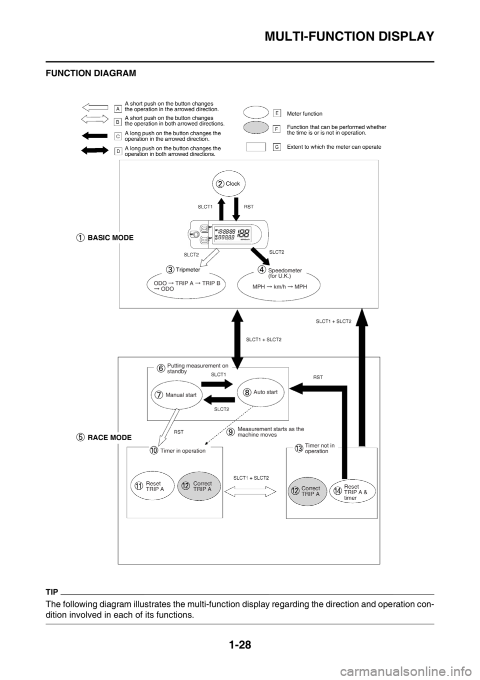
EAS2GB7047FUNCTION DIAGRAM
TIP
The following diagram illustrates the multi-function display regarding the direction and operation con-
dition involved in each of its functions.
A short push on the button changes
the operation in the arrowed direction.
A short push on the button changes
the operation in both arrowed directions.
A long push on the button changes the
operation in the arrowed direction.
A long push on the button changes the
operation in both arrowed directions.Meter function
Function that can be performed whether
the time is or is not in operation.
Extent to which the meter can operate
Clock
BASIC MODE
Tripmeter
ODO TRIP A TRIP B ODO
Speedometer
(for U.K.)
MPH
km/h MPH
Putting measurement on
standby
Manual startAuto start
RACE MODE
Timer in operation
Reset
TRIP ACorrect
TRIP AMeasurement starts as the
machine moves
Timer not in
operation
Correct
TRIP AReset
TRIP A &
timer
Page 43 of 428

MULTI-FUNCTION DISPLAY
1-29
A.A short push on the button changes the oper-
ation in the arrowed direction.
B.A short push on the button changes the oper-
ation in both arrowed directions.
C.A long push on the button changes the oper-
ation in the arrowed direction.
D.A long push on the button changes the oper-
ation in both arrowed directions.
E.Meter function
F.Function that can be performed whether the
time is or is not in operation.
G.Extent to which the meter can operate
1. BASIC MODE
2. Clock
3. Trip meter
4. Speedometer (for U.K.)
5. RACE MODE
6. Putting measurement on standby
7. Manual start
8. Auto start
9. Measurement starts as the machine moves
10.Timer in operation
11.Reset TRIP A
12.Correct TRIP A
13.Timer not in operation
14.Reset TRIP A and timer
Page 44 of 428
STARTING AND BREAK-IN
1-30
EAS2GB7048
STARTING AND BREAK-IN
EAS2GB7049FUEL
Always use the recommended fuel as stated
below. Also, be sure to use new gasoline the
day of a race.
ECA
NOTICE
Use only unleaded gasoline. The use of
leaded gasoline will cause severe damage
to the engine internal parts such as valves,
piston rings, and exhaust system, etc.
TIP
Your Yamaha engine has been designed to use
premium unleaded gasoline with a pump oc-
tane number [(R+M)/2] of 91 or higher, or a re-
search octane number of 95 or higher. If
knocking (or pinging) occurs, use a gasoline of
a different brand.
EWA
WARNING
• For refueling, be sure to stop the engine
and use enough care not to spill any fuel.
Also be sure to avoid refueling close to a
fire.
• Refuel after the engine, exhaust pipe, etc.
have cooled off.
Gasohol (For USA and Canada)
There are two types of gasohol: gasohol con-
taining ethanol and that containing methanol.
Gasohol containing ethanol can be used if the
ethanol content does not exceed 10%. Gasohol
containing methanol is not recommended by
Yamaha because it can cause damage to the
fuel system or vehicle performance problems.
EAS2GB7050HANDLING NOTEEWA
WARNING
Never start or run the engine in a closed ar-
ea. The exhaust fumes are poisonous; they
can cause loss of consciousness and death
in a very short time. Always operate the ma-
chine in a well-ventilated area.
ECA
NOTICE
• Unlike a two-stroke engine, this engine
cannot be kick started when the throttle is
open because the kickstarter may kick
back. Also, if the throttle is open the air/
fuel mixture may be too lean for the engine
to start.
• Before starting the machine, perform the
checks in the pre-operation check list.
EAS2GB7051AIR FILTER MAINTENANCE
According to “CLEANING THE AIR FILTER
ELEMENT” section in the CHAPTER 3, apply
the foam-air-filter oil or its equivalent to the ele-
ment. (Excess oil in the element may adversely
affect engine starting.)
EAS2GB7052STARTING A COLD ENGINEECA
NOTICE
For maximum engine life, never accelerate
hard when the engine is cold!
In order for the ignition circuit cut-off system to
enable starting, one of the following conditions
must be met:
• The transmission is in the neutral position.
• The transmission is in gear with the clutch le-
ver pulled.
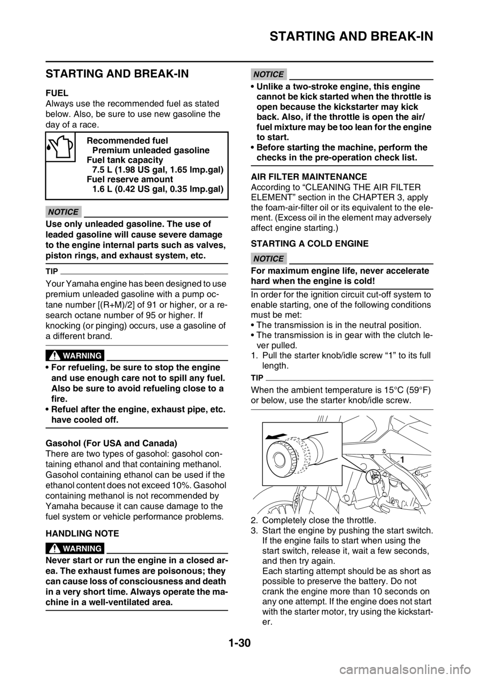
1. Pull the starter knob/idle screw “1” to its full
length.
TIP
When the ambient temperature is 15°C (59°F)
or below, use the starter knob/idle screw.
2. Completely close the throttle.
3. Start the engine by pushing the start switch.
If the engine fails to start when using the
start switch, release it, wait a few seconds,
and then try again.
Each starting attempt should be as short as
possible to preserve the battery. Do not
crank the engine more than 10 seconds on
any one attempt. If the engine does not start
with the starter motor, try using the kickstart-
er. Recommended fuel
Premium unleaded gasoline
Fuel tank capacity
7.5 L (1.98 US gal, 1.65 lmp.gal)
Fuel reserve amount
1.6 L (0.42 US gal, 0.35 lmp.gal)
1
Page 45 of 428
STARTING AND BREAK-IN
1-31
ECA
NOTICE
If the starter motor will not turn when the
start switch is pushed, stop pushing it im-
mediately in order to avoid placing extra
load on the starter motor, and start the en-
gine by using the kickstarter.
TIP
If the engine fails to start, push the engine stop
switch and give the kickstarter 10 to 20 slow
kicks at full throttle in order to clear the engine
of the rich air-fuel mixture retained in it.
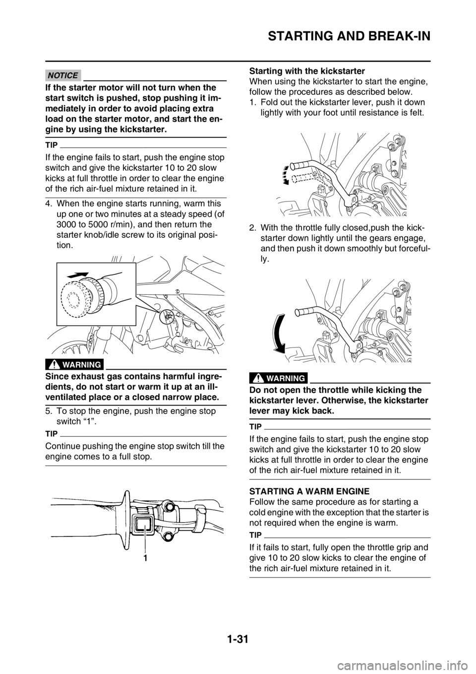
4. When the engine starts running, warm this
up one or two minutes at a steady speed (of
3000 to 5000 r/min), and then return the
starter knob/idle screw to its original posi-
tion.
EWA
WARNING
Since exhaust gas contains harmful ingre-
dients, do not start or warm it up at an ill-
ventilated place or a closed narrow place.
5. To stop the engine, push the engine stop
switch “1”.
TIP
Continue pushing the engine stop switch till the
engine comes to a full stop.Starting with the kickstarter
When using the kickstarter to start the engine,
follow the procedures as described below.
1. Fold out the kickstarter lever, push it down
lightly with your foot until resistance is felt.
2. With the throttle fully closed,push the kick-
starter down lightly until the gears engage,
and then push it down smoothly but forceful-
ly.
EWA
WARNING
Do not open the throttle while kicking the
kickstarter lever. Otherwise, the kickstarter
lever may kick back.
TIP
If the engine fails to start, push the engine stop
switch and give the kickstarter 10 to 20 slow
kicks at full throttle in order to clear the engine
of the rich air-fuel mixture retained in it.
EAS2GB7053STARTING A WARM ENGINE
Follow the same procedure as for starting a
cold engine with the exception that the starter is
not required when the engine is warm.
TIP
If it fails to start, fully open the throttle grip and
give 10 to 20 slow kicks to clear the engine of
the rich air-fuel mixture retained in it.
Page 46 of 428
STARTING AND BREAK-IN
1-32
EAS2GB7054BREAK-IN PROCEDURES
A break-in is important so that rotating portion,
sliding surfaces, and mounted areas may fit
one another, and that the rider may become ac-
customed to the machine.
ECA
NOTICE
Before running, do maintenance on the air
filter element.
Refer to “CLEANING THE AIR FILTER ELE-
MENT” on page 3-14.
1. After warming up the engine, drive it for
about 20 minutes at a throttle opening of 1/2
or less.
2. Make a pit stop, and check mounted areas
for looseness, oil leaks, or other problems.
3. Then, drive it for about 40 minutes at a throt-
tle opening of 3/4 or less.
4. Make a pit stop again, and thoroughly check
mounted areas for looseness, oil leaks, or
other problems. Thorough checks and ad-
justments are required in particular for
stretch of cables, free play of the brake,
stretch of the drive chain, looseness of the
spoke, and so on.
ECA
NOTICE
After a break-in or after each race, always
check the points shown in “TORQUE-
CHECK POINTS” for tightening torques and
retighten them. (Refer to “TORQUE-CHECK
POINTS” on page 1-34.)
Also when the following parts are replaced,
a break-in is required.
• Cylinder and Crankshaft: A break-in is re-
quired for about an hour.
• Piston, Piston ring, Valve, Camshaft, and
Gear: A break-in is required for about 30
minutes at a throttle opening of 1/2 or less.
Observe the condition of the engine careful-
ly during a break-in.
For checkpoints for a break-in, see “MAIN-
TENANCE AFTER BREAK-IN”. If any prob-
lem is found, immediately stop the engine
and make a checkup.
Page 47 of 428
MAINTENANCE AFTER BREAK-IN
1-33
EAS2GB7055
MAINTENANCE AFTER BREAK-IN
After a break-in, perform careful maintenance
to get ready for the next practice or race.
Refer to “PRE-OPERATION INSPECTION
AND MAINTENANCE” on page 3-9.
EAS2GB7056MAJOR MAINTENANCE
1. For the engine
• Leaks around the engine
Check for pressure leaks from the cylinder
head or the cylinder, oil leaks from the
crankcase or the case cover, leaks from the
coolant system, and other leaks.
• Check that the valve, the cylinder head, the
cylinder, the piston, and the piston ring fit
one another, and that contact between the
valve and the cylinder head, and that be-
tween the cylinder and the piston are cor-
rect.
• Engine oil change
Drain the oil, and check for dirt and foreign
materials such as metal chips. (If any foreign
material is mixed, disassemble and check
the crankcase.)
Pour the specified amount of the recom-
mended oil.
• AC magneto
Check for looseness in mounted areas of
the rotor and the stator.
Check that the connector is not being dis-
connected.
• Silencer
Check the main body and stay for cracks.
Check for leaks.
• Mounting bolts and nuts
Check for looseness in mounted areas of
parts, as well as engine mounting bolts and
engine brackets.
2. For the chassis
• Check welds and mounted areas of the
frame, the swingarm, the link, the bracket,
and so on, for looseness and cracks.
• Wheel (s)
Check the wheel for runout. Check the
spoke for looseness.
• Brake(s)
Check the brake disc mounting bolt for
looseness.
Check that the reservoir contains the speci-
fied amount of brake fluid. Check for leaks.• Cable
Grease and adjust cables.
•Drive chain
Lubricate the drive chain and adjust its ten-
sion.
• Fuel tank
Clean the inside of the fuel tank. Check for
leaks.
• Suspension
Check for oil leaks in the front fork or the rear
shock absorber. Check that the mounted
conditions are good.
• Sprocket
Check for looseness in the sprocket mount-
ed on the rear wheel.
• Mounting bolts and nuts
Check mounted areas for looseness.
ECA
NOTICE
After a break-in or before each race, always
check the points shown in “TORQUE-
CHECK POINTS” for tightening torques and
retighten them. (Refer to “TORQUE-CHECK
POINTS” on page 1-34.)
• Greasing and oiling
Always grease or oil the specified points.
Page 48 of 428

TORQUE-CHECK POINTS
1-34
EAS2GB7057
TORQUE-CHECK POINTS
Frame construction Frame to rear frame
Frame to engine protector
Combined seat and fuel tank Fuel tank to frame
Engine mounting Frame to engine
Engine bracket to engine
Engine bracket to frame
Seat Seat to frame
Steering Steering stem to handlebar Steering stem to frame
Steering stem to upper bracket
Upper bracket to handlebar
Suspension Front Steering stem to front fork Front fork to upper bracket
Front fork to lower bracket
Rear Link Assembly of links
Link to frame
Link to rear shock absorber
Link to swingarm
Mounting of rear shock absorber Rear shock absorber and frame
Mounting of swingarm Tightening of pivot shaft
Wheel (s) Mounting of wheel Front Tightening of wheel axle
Tightening of axle holder
Tightening of spoke nipple
Rear Tightening of wheel axle
Wheel to rear wheel sprocket
Tightening of spoke nipple
Brake(s) Front Brake caliper to front fork
Brake disc to wheel
Tightening of union bolt
Brake master cylinder to handle-
bar
Tightening of bleed screw
Tightening of brake hose holder
Rear Brake pedal to frame
Brake disc to wheel
Tightening of union bolt
Brake master cylinder to frame
Tightening of bleed screw
Tightening of brake hose holder
Shift pedal Shift pedal to shift shaft
Page 49 of 428
TORQUE-CHECK POINTS
1-35
TIP
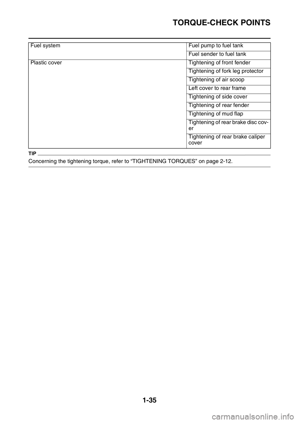
Concerning the tightening torque, refer to “TIGHTENING TORQUES” on page 2-12.Fuel system Fuel pump to fuel tank
Fuel sender to fuel tank
Plastic cover Tightening of front fender
Tightening of fork leg protector
Tightening of air scoop
Left cover to rear frame
Tightening of side cover
Tightening of rear fender
Tightening of mud flap
Tightening of rear brake disc cov-
er
Tightening of rear brake caliper
cover
Page 50 of 428
MOTORCYCLE CARE AND STORAGE
1-36
EAS2GB7058
MOTORCYCLE CARE AND STOR-
AGE
EAS2GB7059CARE
While the open design of a motorcycle reveals
the attractiveness of the technology, it also
makes it more vulnerable. Rust and corrosion
can develop even if high-quality components
are used. A rusty exhaust pipe may go unno-
ticed on a car, however, it detracts from the
overall appearance of a motorcycle. Frequent
and proper care does not only comply with the
terms of the warranty, but it will also keep your
motorcycle looking good, extend its life and op-
timize its performance.
Before cleaning
1. Cover the muffler outlet with a plastic bag af-
ter the engine has cooled down.
2. Make sure that all caps and covers as well
as all electrical couplers and connectors, in-
cluding the spark plug cap, are tightly in-
stalled.
3. Remove extremely stubborn dirt, like oil
burnt onto the crankcase, with a degreasing
agent and a brush, but never apply such
products onto seals, gaskets, sprockets, the
drive chain and wheel axles. Always rinse
the dirt and degreaser off with water.
Cleaning
ECA
NOTICE
• Avoid using strong acidic wheel cleaners,
especially on spoked wheels. If such prod-
ucts are used on hard-to-remove dirt, do
not leave the cleaner on the affected area
any longer than instructed. Also, thor-
oughly rinse the area off with water, imme-
diately dry it, and then apply a corrosion
protection spray.
• Improper cleaning can damage plastic
parts (such as cowlings, panels, wind-
shields, headlight lenses, meter lenses,
etc.) and the mufflers. Use only a soft,
clean cloth or sponge with water to clean
plastic. However, if the plastic parts can-
not be thoroughly cleaned with water, di-
luted mild detergent with water may be
used. Be sure to rinse off any detergent
residue using plenty of water, as it is
harmful to plastic parts.• Do not use any harsh chemical products
on plastic parts. Be sure to avoid using
cloths or sponges which have been in con-
tact with strong or abrasive cleaning prod-
ucts, solvent or thinner, fuel (gasoline),
rust removers or inhibitors, brake fluid,
antifreeze or electrolyte.
• Do not use high-pressure washers or
steam-jet cleaners since they cause water
seepage and deterioration in the following
areas: seals (of wheel and swingarm bear-
ings, fork and brakes), electric compo-
nents (couplers, connectors, instruments,
switches and lights), breather hoses and
vents.
• For motorcycles equipped with a wind-
shield: Do not use strong cleaners or hard
sponges as they will cause dulling or
scratching. Some cleaning compounds for
plastic may leave scratches on the wind-
shield. Test the product on a small hidden
part of the windshield to make sure that it
does not leave any marks. If the wind-
shield is scratched, use a quality plastic
polishing compound after washing.
After normal use
Remove dirt with warm water, a mild detergent,
and a soft, clean sponge, and then rinse thor-
oughly with clean water. Use a toothbrush or
bottlebrush for hard-to-reach areas. Stubborn
dirt and insects will come off more easily if the
area is covered with a wet cloth for a few min-
utes before cleaning.
After riding in the rain, near the sea or on salt-
sprayed roads
Since sea salt or salt sprayed on roads during
winter are extremely corrosive in combination
with water, carry out the following steps after
each ride in the rain, near the sea or on salt-
sprayed roads.
TIP
Salt sprayed on roads in the winter may remain
well into spring.
1. Clean the motorcycle with cold water and a
mild detergent, after the engine has cooled
down.
NOTICE: Do not use warm water since it
increases the corrosive action of the salt.