YAMAHA WR 250F 2016 Manual PDF
Manufacturer: YAMAHA, Model Year: 2016, Model line: WR 250F, Model: YAMAHA WR 250F 2016Pages: 428, PDF Size: 14.13 MB
Page 71 of 428

TIGHTENING TORQUES
2-18
Drive chain tensioner bolt (lower
side)M8 1 16 Nm (1.6 m·kgf, 12 ft·lbf)
Drive chain support bolt M6 1 7 Nm (0.7 m·kgf, 5.1 ft·lbf)
Drive chain support nut M6 2 7 Nm (0.7 m·kgf, 5.1 ft·lbf)
Drive chain guide bolt M5 3 4.0 Nm (0.40 m·kgf, 2.9 ft·lbf)
Rear frame and left cover bolt M6 2 7 Nm (0.7 m·kgf, 5.1 ft·lbf)
Fuel tank bolt (front side) M6 2 7 Nm (0.7 m·kgf, 5.1 ft·lbf)
Fuel tank bolt (rear side) M6 1 9 Nm (0.9 m·kgf, 6.5 ft·lbf)
Fuel tank bracket bolt (front side) M6 4 7 Nm (0.7 m·kgf, 5.1 ft·lbf)
Fuel tank bracket bolt (rear side) M6 2 7 Nm (0.7 m·kgf, 5.1 ft·lbf)
Fuel pump bolt M5 6 4.0 Nm (0.40 m·kgf, 2.9 ft·lbf)
Fuel sender screw M6 2 4.0 Nm (0.40 m·kgf, 2.9 ft·lbf)
Fuel inlet pipe screw M5 2 3.4 Nm (0.34 m·kgf, 2.5 ft·lbf)
Fuel tank cap cover bolt M6 2 4.0 Nm (0.40 m·kgf, 2.9 ft·lbf)
Seat set bracket and fuel tank screw M6 1 7 Nm (0.7 m·kgf, 5.1 ft·lbf)
Seat bolt M8 2 22 Nm (2.2 m·kgf, 16 ft·lbf)
Left side cover bolt M6 1 7 Nm (0.7 m·kgf, 5.1 ft·lbf)
Right side cover bolt M6 2 7 Nm (0.7 m·kgf, 5.1 ft·lbf)
Frame and air scoop bolt M6 2 7 Nm (0.7 m·kgf, 5.1 ft·lbf)
Fuel tank and air scoop bolt M6 2 7 Nm (0.7 m·kgf, 5.1 ft·lbf)
Radiator guard and air scoop bolt M6 4 7 Nm (0.7 m·kgf, 5.1 ft·lbf)
Front fender bolt M6 4 10 Nm (1.0 m·kgf, 7.2 ft·lbf)
Rear fender bolt (front side) M6 4 7 Nm (0.7 m·kgf, 5.1 ft·lbf)
Rear fender bolt (rear side) M6 2 16 Nm (1.6 m·kgf, 12 ft·lbf)
Mud flap screw — 2 1.3 Nm (0.13 m·kgf, 0.94 ft·lbf)
Headlight body and headlight stay
boltM6 2 7 Nm (0.7 m·kgf, 5.1 ft·lbf)
Multi-function meter nut M5 2 3.8 Nm (0.38 m·kgf, 2.8 ft·lbf)
Multi-function meter bracket bolt M6 1 7 Nm (0.7 m·kgf, 5.1 ft·lbf)
Front brake hose guide and head-
light stay boltM5 1 3.8 Nm (0.38 m·kgf, 2.8 ft·lbf)
Plate 1 and front fork protector bolt M5 2 3.8 Nm (0.38 m·kgf, 2.8 ft·lbf)
Plate 2 and front fork protector
screw— 2 0.5 Nm (0.05 m·kgf, 0.36 ft·lbf)
Speed sensor lead holder and
speed sensor lead bracket boltM6 1 7 Nm (0.7 m·kgf, 5.1 ft·lbf)
Speed sensor lead bracket and low-
er bracket boltM6 1 13 Nm (1.3 m·kgf, 9.4 ft·lbf)
Starter relay and positive battery
lead boltM6 1 3.5 Nm (0.35 m·kgf, 2.5 ft·lbf) ITEMThread
sizeQ’ty TIGHTENING TORQUES Remarks
Page 72 of 428

TIGHTENING TORQUES
2-19
TIP
Lower ring nut
1. First, tighten the lower ring nut approximately 38 Nm (3.8 m·kgf, 27 ft·lbf) by using the steering nut
wrench, then loosen the lower ring nut one turn.
2. Retighten the lower ring nut 7 Nm (0.7 m·kgf, 5.1 ft·lbf).Starter relay and starter motor lead
boltM6 1 3.5 Nm (0.35 m·kgf, 2.5 ft·lbf)
Lean angle sensor bolt M4 2 3.8 Nm (0.38 m·kgf, 2.8 ft·lbf)
Taillight assembly screw — 3 1.1 Nm (0.11 m·kgf, 0.80 ft·lbf)
Taillight lead clamp and rear fender — 3 0.5 Nm (0.05 m·kgf, 0.36 ft·lbf)
Battery bracket bolt M6 4 7 Nm (0.7 m·kgf, 5.1 ft·lbf)
Frame and battery negative lead
boltM6 1 7 Nm (0.7 m·kgf, 5.1 ft·lbf)
Rear fender and relay bracket screw — 2 1.1 Nm (0.11 m·kgf, 0.80 ft·lbf)
Front reflector nut (For Canada) M6 2 3.8 Nm (0.38 m·kgf, 2.8 ft·lbf)
Rear reflector nut (For Canada) M5 3 1.8 Nm (0.18 m·kgf, 1.3 ft·lbf)ITEMThread
sizeQ’ty TIGHTENING TORQUES Remarks
Page 73 of 428

LUBRICATION POINTS AND LUBRICANT TYPES
2-20
EAS2GB7068
LUBRICATION POINTS AND LUBRICANT TYPES
EAS2GB7069ENGINE
Lubrication point Lubricant types
Oil seal lips
Bearing
O-ring
Camshaft cap bolt threads and contacting surface
Cylinder head bolt threads, seats, washers
Valve stems
Valve stem ends
Valve lifter outer surface
Camshaft lobe and journal
Valve lifter top surface
Crankshaft journal
Crankshaft big end thrust surfaces
Piston outer surface
Piston pin outer surface
Balancer shaft journal (left)
Balancer nut threads (left)
Decompression system moving parts
Water pump impeller shaft
Oil pump rotors (inner and outer)
Oil passage gasket
Oil pump shaft
Kick gear and ratchet wheel
Kick shaft
Kick idle gear inner surface
Ratchet wheel and ratchet wheel guide contacting portion
Primary drive gear nut threads and contacting surface
Primary driven gear inner surface and end surface
Clutch push rod washer
Clutch push rod 1 outer surface
Clutch push rod 1 thrust surface
Clutch push rod 2 outer surface
Push lever shaft outer surface
Transmission gear inner surface (wheel and pinion) and collar
Transmission gears (shift fork groove)
Shift cam grooves
Shift fork and shift fork guide outer surface
Shift shaft
LS
E
LS
E
M
M
M
E
M
M
M
E
E
E
M
E
E
E
E
LS
E
M
E
E
M
E
E
E
E
E
E
E
M
E
E
E
E
Page 74 of 428

LUBRICATION POINTS AND LUBRICANT TYPES
2-21
EAS2GB7070CHASSISShift lever assembly moving parts
Damper assembly shaft, thrust surfaces, washers
Starter idle gear inner surface, thrust surfaces
Starter clutch drive gear inner surface, thrust surfaces
Cylinder head cover gasketThree bond
No.1215®
Crankcase mating surfaceThree bond
No.1215®
Stator assembly lead grommetThree bond
No.1215®
Lubrication point Lubricant types
Upper bearings (steering head)
Upper bearings and bearing race cover (steering head)
Lower bearings and oil seal lip (steering head)
Steering stem threads and nut contacting surface
Pivot shaft bearing
Swingarm pivot portion (collar side surface and thrust bearing)
Swingarm pivot portion (collar outer surface)
Swingarm pivot portion (oil seal lip)
Pivot shaft outer surface
Relay arm bearing and oil seal lip
Relay arm thrust washer surface (both sides)
Relay arm collar outer surface and bolt outer surface
Relay arm bolt threads (swingarm side)
Connecting arm bearing and oil seal lip
Connecting arm collar outer surface and bolt outer surface
Rear shock absorber assembly collar outer surface and dust seal lip (upper
side)
Rear shock absorber assembly bearing and dust seal lip (lower side)
Brake pedal pivot portion (O-ring and bolt outer surface)
Front wheel oil seal lip
Front wheel axle outer surface
Speed sensor oil seal lip
Rear wheel oil seal lip
Rear wheel axle outer surface
Sidestand pivot portion and collar outer surface
Brake lever contacting portion (front brake master cylinder)
Front brake lever bolt outer surface
Clutch lever sliding surface and bolt outer surfaceLubrication point Lubricant types
E
E
E
E
LS
LS
LS
LS
M
M
M
M
M
M
M
M
M
M
M
M
M
LS
LS
LS
LS
LS
LS
LS
S
S
LS
Page 75 of 428

LUBRICATION POINTS AND LUBRICANT TYPES
2-22
Clutch lever adjuster rubber lip
Clutch cable end (clutch lever side)
Tube guide (throttle grip) inner surface and throttle cable end
Front brake caliper piston
Front brake caliper piston seal
Front brake caliper dust seal
Front brake caliper piston outer surface
Front brake caliper pin bolt and boot
Front brake master cylinder push rod end
Front brake master cylinder kit
Rear brake caliper piston
Rear brake caliper piston seal
Rear brake caliper dust seal
Rear brake caliper piston outer surface
Rear brake caliper pin bolt and boot
Rear brake master cylinder push rod end
Rear brake master cylinder kitLubrication point Lubricant typesLS
LS
LS
S
S
S
S
S
S
S
S
Page 76 of 428

LUBRICATION SYSTEM CHART AND DIAGRAMS
2-23
EAS2GB7071
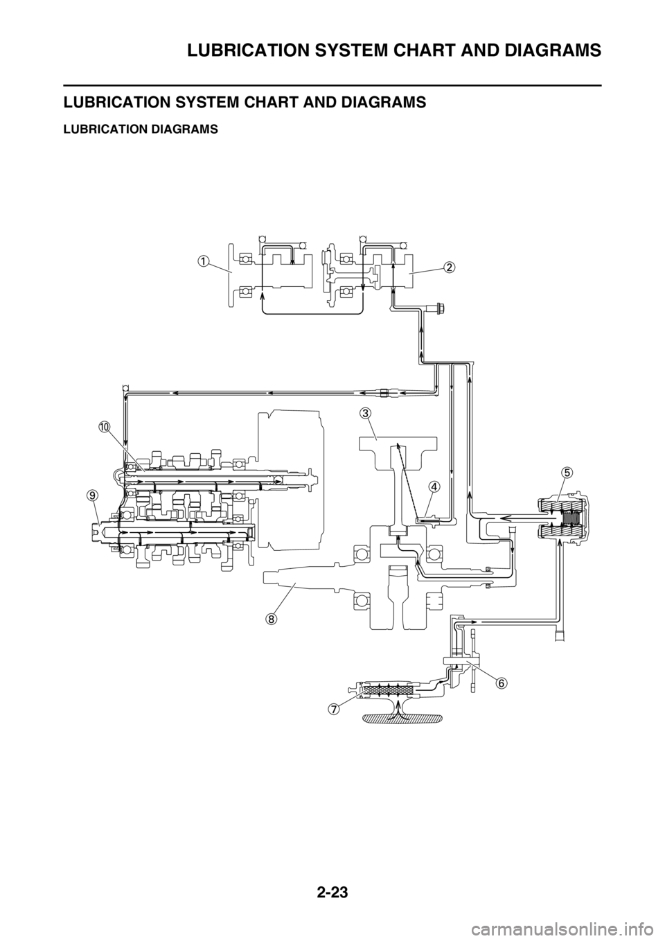
LUBRICATION SYSTEM CHART AND DIAGRAMS
EAS2GB7072LUBRICATION DIAGRAMS
Page 77 of 428

LUBRICATION SYSTEM CHART AND DIAGRAMS
2-24
1. Intake camshaft
2. Exhaust camshaft
3. Piston
4. Oil nozzle
5. Oil filter element
6. Oil pump
7. Oil strainer
8. Crankshaft
9. Drive axle
10. Main axle
Page 78 of 428

LUBRICATION SYSTEM CHART AND DIAGRAMS
2-25
Page 79 of 428

LUBRICATION SYSTEM CHART AND DIAGRAMS
2-26
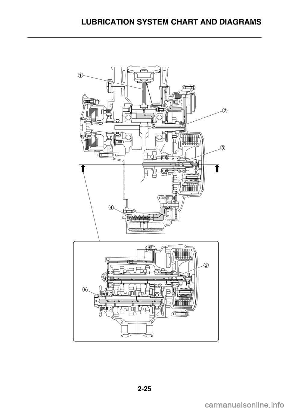
1. Connecting rod
2. Crankshaft
3. Main axle
4. Oil strainer
5. Drive axle
Page 80 of 428

LUBRICATION SYSTEM CHART AND DIAGRAMS
2-27