YAMAHA WR 400F 2001 Owners Manual
Manufacturer: YAMAHA, Model Year: 2001, Model line: WR 400F, Model: YAMAHA WR 400F 2001Pages: 762, PDF Size: 62.36 MB
Page 281 of 762
INSP
ADJ
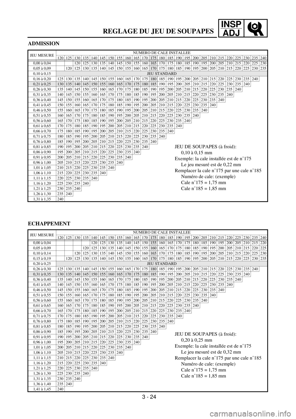
ADMISSION
JEU MESURENUMERO DE CALE INSTALLEE
120 125 130 135 140 145 150 155 160 165 170175 180 185 190 195 200 205 210 215 220 225 230 235 240
0,00 à 0,04 120 125 130 135 140 145 150 155
160165 170 175 180 185 190 195 200 205 210 215 220 225 230
0,05 à 0,09
120 125 130 135 140 145 150 155 160 165170 175 180 185 190 195 200 205 210 215 220 225 230 235
0,10 à 0,15
JEU STANDARD
0,16 à 0,20125130135140145150155160165170175180 185 190 195 200 205 210 215 220 225 230 235240
0,21 à 0,25130135140145150155160165170175180185 190 195 200 205 210 215 220 225 230 235240
0,26 à 0,30 135 140 145 150 155 160 165 170 175 180 185 190 195 200 205 210 215 220 225 230 235240
0,31 à 0,35 140 145 150 155 160 165 170 175 180 185 190 195 200 205 210 215 220 225 230 235240
0,36 à 0,40 145 150 155 160 165 170 175 180 185 190 195 200 205 210 215 220 225 230 235240
0,41 à 0,45 150 155 160 165 170 175 180 185 190 195 200 205 210 215 220 225 230 235240
0,46 à 0,50 155 160 165 170 175 180 185 190 195 200 205 210 215 220 225 230 235240
0,51 à 0,55 160 165 170 175 180 185 190 195 200 205 210 215 220 225 230 235240
0,56 à 0,60 165 170 175 180 185 190 195 200 205 210 215 220 225 230 235240
0,61 à 0,65 170 175 180 185 190 195 200 205 210 215 220 225 230 235240
0,66 à 0,70 175 180 185 190 195 200 205 210 215 220 225 230 235240
0,71 à 0,75 180 185 190 195 200 205 210 215 220 225 230 235240
0,76 à 0,80 185 190 195 200 205 210 215 220 225 230 235240
JEU DE SOUPAPES (à froid):
0,10 à 0,15 mm
Exemple: la cale installée est de n˚175
Le jeu mesuré est de 0,22 mm
Remplacer la cale n˚175 par une cale n˚185
Numéro de cale: (exemple)
Cale n˚175 = 1,75 mm
Cale n˚185 = 1,85 mm0,81 à 0,85 190 195 200 205 210 215 220 225 230 235240
0,86 à 0,90 195 200 205 210 215 220 225 230 235240
0,91 à 0,95 200 205 210 215 220 225 230 235240
0,96 à 1,00 205 210 215 220 225 230 235240
1,01 à 1,05 210 215 220 225 230 235240
1,06 à 1,10 215 220 225 230 235240
1,11 à 1,15 220 225 230 235240
1,16 à 1,20 225 230 235240
1,21 à 1,25 230 235240
1,26 à 1,30 235240
1,31 à 1,35 240
ECHAPPEMENT
JEU MESURENUMERO DE CALE INSTALLEE
120 125 130 135 140 145 150 155 160 165 170175 180 185 190 195 200 205 210 215 220 225 230 235 240
0,00 à 0,04 120 125 130 135 140 145
150155 160 165 170 175 180 185 190 195 200 205 210 215 220
0,05 à 0,09
120 125 130 135 140 145 150 155160 165 170 175 180 185 190 195 200 205 210 215 220 225
0,10 à 0,14
120 125 130 135 140 145 150 155 160165 170 175 180 185 190 195 200 205 210 215 220 225 230
0,15 à 0,19120125130135140145150155160165170 175 180 185 190 195 200 205 210 215 220 225230235
0,20 à 0,25
JEU STANDARD
0,26 à 0,30 125 130 135 140 145 150 155 160 165 170 175180 185 190 195 200 205 210 215 220 225230235240
0,31 à 0,35130135140145150155160165170175180185 190 195 200 205 210 215 220 225230235240
0,36 à 0,40 135 140 145 150 155 160 165 170 175 180 185 190 195 200 205 210 215 220 225230235240
0,41 à 0,45 140 145 150 155 160 165 170 175 180 185 190 195 200 205 210 215 220 225230235240
0,46 à 0,50 145 150 155 160 165 170 175 180 185 190 195 200 205 210 215 220 225230235240
0,51 à 0,55 150 155 160 165 170 175 180 185 190 195 200 205 210 215 220 225230235240
0,56 à 0,60 155 160 165 170 175 180 185 190 195 200 205 210 215 220 225230235240
0,61 à 0,65 160 165 170 175 180 185 190 195 200 205 210 215 220 225230235240
0,66 à 0,70 165 170 175 180 185 190 195 200 205 210 215 220 225230235240
0,71 à 0,75 170 175 180 185 190 195 200 205 210 215 220 225230235240
0,76 à 0,80 175 180 185 190 195 200 205 210 215 220 225230235240
0,81 à 0,85 180 185 190 195 200 205 210 215 220 225230235240
0,86 à 0,90 185 190 195 200 205 210 215 220 225230235240JEU DE SOUPAPES (à froid):
0,20 à 0,25 mm
Exemple: la cale installée est de n˚175
Le jeu mesuré est de 0,32 mm
Remplacer la cale n˚175 par une cale n˚185
Numéro de cale: (exemple)
Cale n˚175 = 1,75 mm
Cale n˚185 = 1,85 mm0,91 à 0,95 190 195 200 205 210 215 220 225230235240
0,96 à 1,00 195 200 205 210 215 220 225230235240
1,01 à 1,05 200 205 210 215 220 225230235240
1,06 à 1,10 205 210 215 220 225230235240
1,11 à 1,15 210 215 220 225230235240
1,16 à 1,20 215 220 225230235240
1,21 à 1,25 220 225230235240
1,26 à 1,30 225230235240
1,31 à 1,35 230235240
1,36 à 1,40 235240
1,41 à 1,45 240
REGLAGE DU JEU DE SOUPAPES
3 - 24
Page 282 of 762
INSP
ADJ
VENTILSPIEL EINSTELLEN
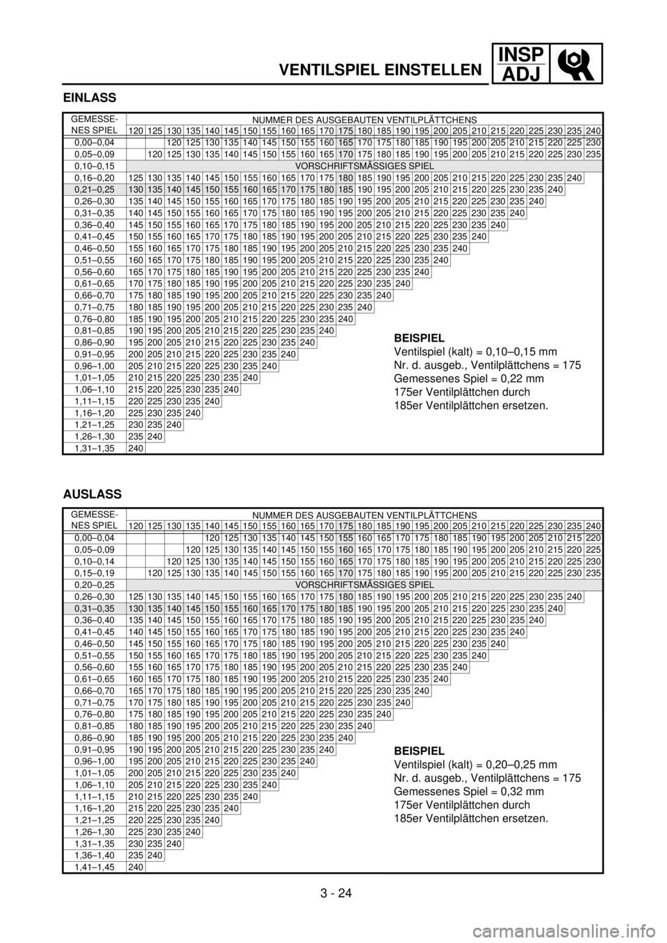
EINLASS
GEMESSE-
NES SPIELNUMMER DES AUSGEBAUTEN VENTILPLÄTTCHENS
120 125 130 135 140 145 150 155 160 165 170
175 180 185 190 195 200 205 210 215 220 225 230 235 240
0,00–0,04 120 125 130 135 140 145 150 155
160165 170 175 180 185 190 195 200 205 210 215 220 225 230
0,05–0,09
120 125 130 135 140 145 150 155 160 165170 175 180 185 190 195 200 205 210 215 220 225 230 235
0,10–0,15
VORSCHRIFTSMÄSSIGES SPIEL
0,16–0,20125130135140145150155160165170175180 185 190 195 200 205 210 215 220 225 230 235240
0,21–0,25130135140145150155160165170175180185 190 195 200 205 210 215 220 225 230 235240
0,26–0,30 135 140 145 150 155 160 165 170 175 180 185 190 195 200 205 210 215 220 225 230 235240
0,31–0,35 140 145 150 155 160 165 170 175 180 185 190 195 200 205 210 215 220 225 230 235240
0,36–0,40 145 150 155 160 165 170 175 180 185 190 195 200 205 210 215 220 225 230 235240
0,41–0,45 150 155 160 165 170 175 180 185 190 195 200 205 210 215 220 225 230 235240
0,46–0,50 155 160 165 170 175 180 185 190 195 200 205 210 215 220 225 230 235240
0,51–0,55 160 165 170 175 180 185 190 195 200 205 210 215 220 225 230 235240
0,56–0,60 165 170 175 180 185 190 195 200 205 210 215 220 225 230 235240
0,61–0,65 170 175 180 185 190 195 200 205 210 215 220 225 230 235240
0,66–0,70 175 180 185 190 195 200 205 210 215 220 225 230 235240
0,71–0,75 180 185 190 195 200 205 210 215 220 225 230 235240
0,76–0,80 185 190 195 200 205 210 215 220 225 230 235240
BEISPIEL
Ventilspiel (kalt) = 0,10–0,15 mm
Nr. d. ausgeb., Ventilplättchens = 175
Gemessenes Spiel = 0,22 mm
175er Ventilplättchen durch
185er Ventilplättchen ersetzen.0,81–0,85 190 195 200 205 210 215 220 225 230 235240
0,86–0,90 195 200 205 210 215 220 225 230 235240
0,91–0,95 200 205 210 215 220 225 230 235240
0,96–1,00 205 210 215 220 225 230 235240
1,01–1,05 210 215 220 225 230 235240
1,06–1,10 215 220 225 230 235240
1,11–1,15 220 225 230 235240
1,16–1,20 225 230 235240
1,21–1,25 230 235240
1,26–1,30 235240
1,31–1,35 240
AUSLASS
GEMESSE-
NES SPIELNUMMER DES AUSGEBAUTEN VENTILPLÄTTCHENS
120 125 130 135 140 145 150 155 160 165 170
175 180 185 190 195 200 205 210 215 220 225 230 235 240
0,00–0,04 120 125 130 135 140 145
150155 160 165 170 175 180 185 190 195 200 205 210 215 220
0,05–0,09
120 125 130 135 140 145 150 155160 165 170 175 180 185 190 195 200 205 210 215 220 225
0,10–0,14
120 125 130 135 140 145 150 155 160165 170 175 180 185 190 195 200 205 210 215 220 225 230
0,15–0,19120125130135140145150155160165170 175 180 185 190 195 200 205 210 215 220 225230235
0,20–0,25
VORSCHRIFTSMÄSSIGES SPIEL
0,26–0,30 125 130 135 140 145 150 155 160 165 170 175180 185 190 195 200 205 210 215 220 225230235240
0,31–0,35130135140145150155160165170175180185 190 195 200 205 210 215 220 225230235240
0,36–0,40 135 140 145 150 155 160 165 170 175 180 185 190 195 200 205 210 215 220 225230235240
0,41–0,45 140 145 150 155 160 165 170 175 180 185 190 195 200 205 210 215 220 225230235240
0,46–0,50 145 150 155 160 165 170 175 180 185 190 195 200 205 210 215 220 225230235240
0,51–0,55 150 155 160 165 170 175 180 185 190 195 200 205 210 215 220 225230235240
0,56–0,60 155 160 165 170 175 180 185 190 195 200 205 210 215 220 225230235240
0,61–0,65 160 165 170 175 180 185 190 195 200 205 210 215 220 225230235240
0,66–0,70 165 170 175 180 185 190 195 200 205 210 215 220 225230235240
0,71–0,75 170 175 180 185 190 195 200 205 210 215 220 225230235240
0,76–0,80 175 180 185 190 195 200 205 210 215 220 225230235240
0,81–0,85 180 185 190 195 200 205 210 215 220 225230235240
0,86–0,90 185 190 195 200 205 210 215 220 225230235240
BEISPIEL
Ventilspiel (kalt) = 0,20–0,25 mm
Nr. d. ausgeb., Ventilplättchens = 175
Gemessenes Spiel = 0,32 mm
175er Ventilplättchen durch
185er Ventilplättchen ersetzen.0,91–0,95 190 195 200 205 210 215 220 225230235240
0,96–1,00 195 200 205 210 215 220 225230235240
1,01–1,05 200 205 210 215 220 225230235240
1,06–1,10 205 210 215 220 225230235240
1,11–1,15 210 215 220 225230235240
1,16–1,20 215 220 225230235240
1,21–1,25 220 225230235240
1,26–1,30 225230235240
1,31–1,35 230235240
1,36–1,40 235240
1,41–1,45 240
3 - 24
Page 283 of 762
INSP
ADJ
AJUSTE DE LA HOLGURA DE LA VÁLVULA
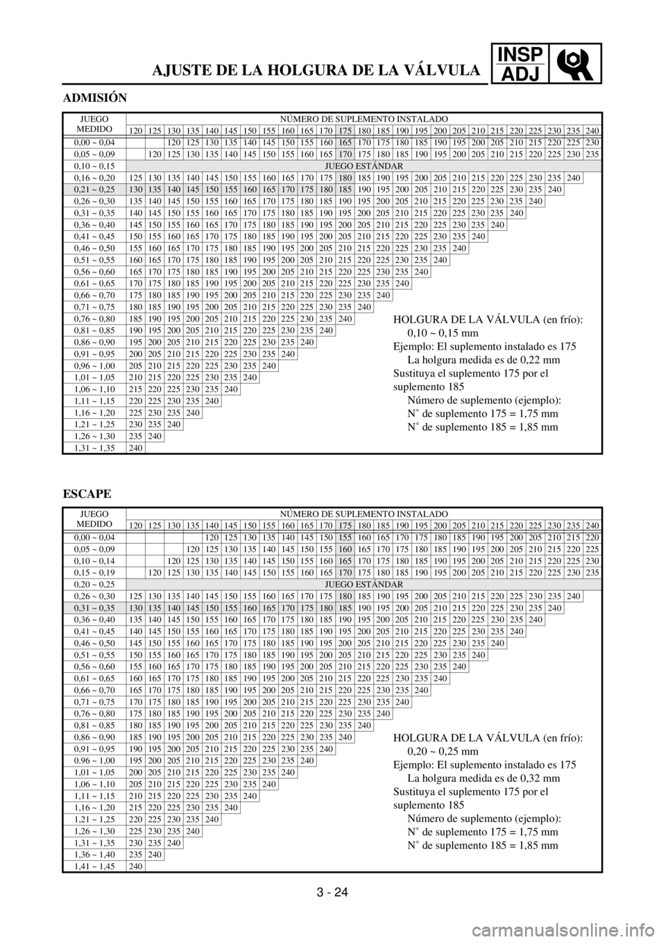
ADMISIÓN
JUEGO
MEDIDONÚMERO DE SUPLEMENTO INSTALADO
120 125 130 135 140 145 150 155 160 165 170
175 180 185 190 195 200 205 210 215 220 225 230 235 240
0,00 ~ 0,04 120 125 130 135 140 145 150 155
160165 170 175 180 185 190 195 200 205 210 215 220 225 230
0,05 ~ 0,09
120 125 130 135 140 145 150 155 160 165170 175 180 185 190 195 200 205 210 215 220 225 230 235
0,10 ~ 0,15
JUEGO ESTÁNDAR
0,16 ~ 0,20125130135140145150155160165170175180 185 190 195 200 205 210 215 220 225 230 235240
0,21 ~ 0,25130135140145150155160165170175180185 190 195 200 205 210 215 220 225 230 235240
0,26 ~ 0,30 135 140 145 150 155 160 165 170 175 180 185 190 195 200 205 210 215 220 225 230 235240
0,31 ~ 0,35 140 145 150 155 160 165 170 175 180 185 190 195 200 205 210 215 220 225 230 235240
0,36 ~ 0,40 145 150 155 160 165 170 175 180 185 190 195 200 205 210 215 220 225 230 235240
0,41 ~ 0,45 150 155 160 165 170 175 180 185 190 195 200 205 210 215 220 225 230 235240
0,46 ~ 0,50 155 160 165 170 175 180 185 190 195 200 205 210 215 220 225 230 235240
0,51 ~ 0,55 160 165 170 175 180 185 190 195 200 205 210 215 220 225 230 235240
0,56 ~ 0,60 165 170 175 180 185 190 195 200 205 210 215 220 225 230 235240
0,61 ~ 0,65 170 175 180 185 190 195 200 205 210 215 220 225 230 235240
0,66 ~ 0,70 175 180 185 190 195 200 205 210 215 220 225 230 235240
0,71 ~ 0,75 180 185 190 195 200 205 210 215 220 225 230 235240
0,76 ~ 0,80 185 190 195 200 205 210 215 220 225 230 235240HOLGURA DE LA VÁLVULA (en frío):
0,10 ~ 0,15 mm
Ejemplo: El suplemento instalado es 175
La holgura medida es de 0,22 mm
Sustituya el suplemento 175 por el
suplemento 185
Número de suplemento (ejemplo):
N˚ de suplemento 175 = 1,75 mm
N˚ de suplemento 185 = 1,85 mm0,81 ~ 0,85 190 195 200 205 210 215 220 225 230 235240
0,86 ~ 0,90 195 200 205 210 215 220 225 230 235240
0,91 ~ 0,95 200 205 210 215 220 225 230 235240
0,96 ~ 1,00 205 210 215 220 225 230 235240
1,01 ~ 1,05 210 215 220 225 230 235240
1,06 ~ 1,10 215 220 225 230 235240
1,11 ~ 1,15 220 225 230 235240
1,16 ~ 1,20 225 230 235240
1,21 ~ 1,25 230 235240
1,26 ~ 1,30 235240
1,31 ~ 1,35 240
ESCAPE
JUEGO
MEDIDONÚMERO DE SUPLEMENTO INSTALADO
120 125 130 135 140 145 150 155 160 165 170
175 180 185 190 195 200 205 210 215 220 225 230 235 240
0,00 ~ 0,04 120 125 130 135 140 145
150155 160 165 170 175 180 185 190 195 200 205 210 215 220
0,05 ~ 0,09
120 125 130 135 140 145 150 155160 165 170 175 180 185 190 195 200 205 210 215 220 225
0,10 ~ 0,14
120 125 130 135 140 145 150 155 160165 170 175 180 185 190 195 200 205 210 215 220 225 230
0,15 ~ 0,19120125130135140145150155160165170 175 180 185 190 195 200 205 210 215 220 225230235
0,20 ~ 0,25
JUEGO ESTÁNDAR
0,26 ~ 0,30 125 130 135 140 145 150 155 160 165 170 175180 185 190 195 200 205 210 215 220 225230235240
0,31 ~ 0,35130135140145150155160165170175180185 190 195 200 205 210 215 220 225230235240
0,36 ~ 0,40 135 140 145 150 155 160 165 170 175 180 185 190 195 200 205 210 215 220 225230235240
0,41 ~ 0,45 140 145 150 155 160 165 170 175 180 185 190 195 200 205 210 215 220 225230235240
0,46 ~ 0,50 145 150 155 160 165 170 175 180 185 190 195 200 205 210 215 220 225230235240
0,51 ~ 0,55 150 155 160 165 170 175 180 185 190 195 200 205 210 215 220 225230235240
0,56 ~ 0,60 155 160 165 170 175 180 185 190 195 200 205 210 215 220 225230235240
0,61 ~ 0,65 160 165 170 175 180 185 190 195 200 205 210 215 220 225230235240
0,66 ~ 0,70 165 170 175 180 185 190 195 200 205 210 215 220 225230235240
0,71 ~ 0,75 170 175 180 185 190 195 200 205 210 215 220 225230235240
0,76 ~ 0,80 175 180 185 190 195 200 205 210 215 220 225230235240
0,81 ~ 0,85 180 185 190 195 200 205 210 215 220 225230235240
0,86 ~ 0,90 185 190 195 200 205 210 215 220 225230235240HOLGURA DE LA VÁLVULA (en frío):
0,20 ~ 0,25 mm
Ejemplo: El suplemento instalado es 175
La holgura medida es de 0,32 mm
Sustituya el suplemento 175 por el
suplemento 185
Número de suplemento (ejemplo):
N˚ de suplemento 175 = 1,75 mm
N˚ de suplemento 185 = 1,85 mm0,91 ~ 0,95 190 195 200 205 210 215 220 225230235240
0.96 ~ 1,00 195 200 205 210 215 220 225230235240
1,01 ~ 1,05 200 205 210 215 220 225230235240
1,06 ~ 1,10 205 210 215 220 225230235240
1,11 ~ 1,15 210 215 220 225230235240
1,16 ~ 1,20 215 220 225230235240
1,21 ~ 1,25 220 225230235240
1,26 ~ 1,30 225230235240
1,31 ~ 1,35 230235240
1,36 ~ 1,40 235240
1,41 ~ 1,45 240
3 - 24
Page 284 of 762
3 - 25
INSP
ADJ
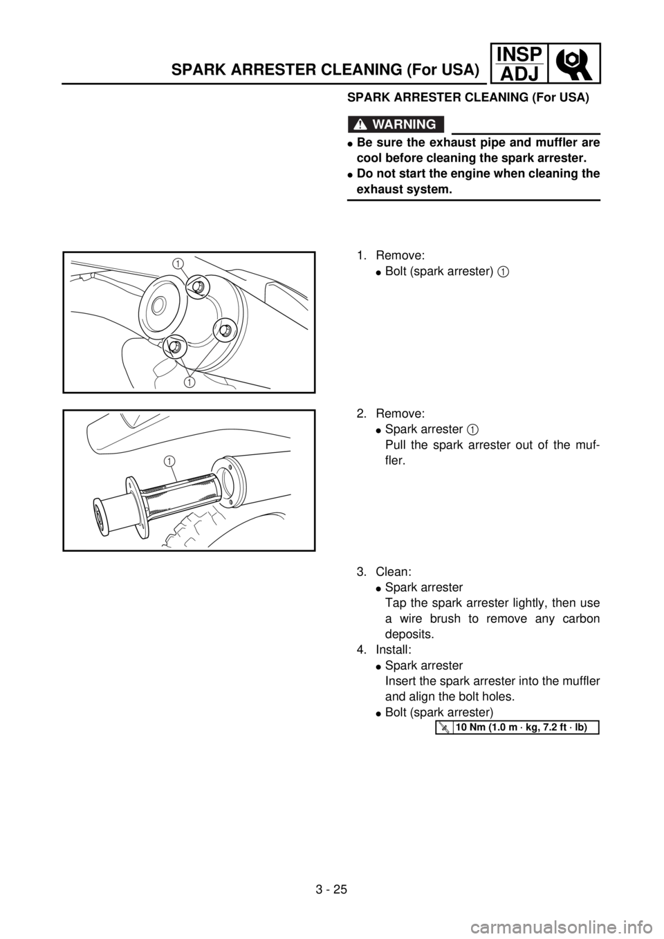
SPARK ARRESTER CLEANING (For USA)
WARNING
lBe sure the exhaust pipe and muffler are
cool before cleaning the spark arrester.
lDo not start the engine when cleaning the
exhaust system.
1. Remove:
lBolt (spark arrester) 1 1
1
2. Remove:
lSpark arrester 1
Pull the spark arrester out of the muf-
fler.
1
3. Clean:
lSpark arrester
Tap the spark arrester lightly, then use
a wire brush to remove any carbon
deposits.
4. Install:
lSpark arrester
Insert the spark arrester into the muffler
and align the bolt holes.
lBolt (spark arrester)
T R..10 Nm (1.0 m · kg, 7.2 ft · lb)
SPARK ARRESTER CLEANING (For USA)
Page 285 of 762
INSP
ADJ
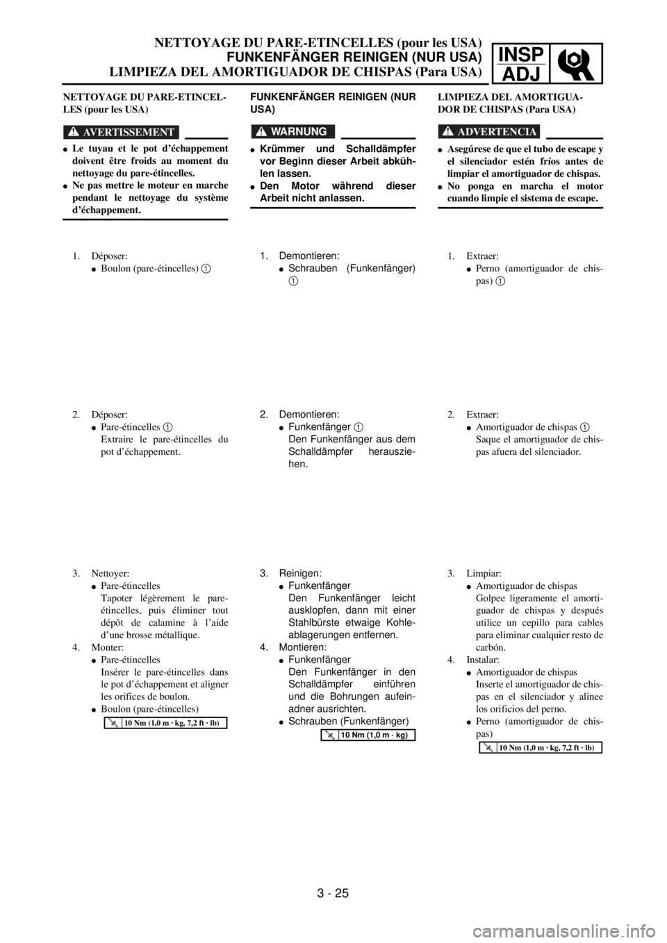
NETTOYAGE DU PARE-ETINCELLES (pour les USA)
FUNKENFÄNGER REINIGEN (NUR USA)
LIMPIEZA DEL AMORTIGUADOR DE CHISPAS (Para USA)
3 - 25
FUNKENFÄNGER REINIGEN (NUR
USA)
WARNUNG
lKrümmer und Schalldämpfer
vor Beginn dieser Arbeit abküh-
len lassen.
lDen Motor während dieser
Arbeit nicht anlassen.
1. Demontieren:
lSchrauben (Funkenfänger)
1
2. Demontieren:
lFunkenfänger 1
Den Funkenfänger aus dem
Schalldämpfer herauszie-
hen.
3. Reinigen:
lFunkenfänger
Den Funkenfänger leicht
ausklopfen, dann mit einer
Stahlbürste etwaige Kohle-
ablagerungen entfernen.
4. Montieren:
lFunkenfänger
Den Funkenfänger in den
Schalldämpfer einführen
und die Bohrungen aufein-
adner ausrichten.
lSchrauben (Funkenfänger)
T R..10 Nm (1,0 m · kg)
NETTOYAGE DU PARE-ETINCEL-
LES (pour les USA)
AVERTISSEMENT
lLe tuyau et le pot d’échappement
doivent être froids au moment du
nettoyage du pare-étincelles.
lNe pas mettre le moteur en marche
pendant le nettoyage du système
d’échappement.
1. Déposer:
lBoulon (pare-étincelles) 1
2. Déposer:
lPare-étincelles 1
Extraire le pare-étincelles du
pot d’échappement.
3. Nettoyer:
lPare-étincelles
Tapoter légèrement le pare-
étincelles, puis éliminer tout
dépôt de calamine à l’aide
d’une brosse métallique.
4. Monter:
lPare-étincelles
Insérer le pare-étincelles dans
le pot d’échappement et aligner
les orifices de boulon.
lBoulon (pare-étincelles)
T R..10 Nm (1,0 m · kg, 7,2 ft · lb)
LIMPIEZA DEL AMORTIGUA-
DOR DE CHISPAS (Para USA)
ADVERTENCIA
lAsegúrese de que el tubo de escape y
el silenciador estén fríos antes de
limpiar el amortiguador de chispas.
lNo ponga en marcha el motor
cuando limpie el sistema de escape.
1. Extraer:
lPerno (amortiguador de chis-
pas) 1
2. Extraer:
lAmortiguador de chispas 1
Saque el amortiguador de chis-
pas afuera del silenciador.
3. Limpiar:
lAmortiguador de chispas
Golpee ligeramente el amorti-
guador de chispas y después
utilice un cepillo para cables
para eliminar cualquier resto de
carbón.
4. Instalar:
lAmortiguador de chispas
Inserte el amortiguador de chis-
pas en el silenciador y alinee
los orificios del perno.
lPerno (amortiguador de chis-
pas)
T R..10 Nm (1,0 m · kg, 7,2 ft · lb)
Page 286 of 762
3 - 26
INSP
ADJ
CHASSIS/BRAKE SYSTEM AIR BLEEDING
EC360000
CHASSIS
EC361012
BRAKE SYSTEM AIR BLEEDING
WARNING
Bleed the brake system if:
lThe system has been disassembled.
lA brake hose has been loosened or
removed.
lThe brake fluid is very low.
lThe brake operation is faulty.
A dangerous loss of braking performance
may occur if the brake system is not prop-
erly bleed.
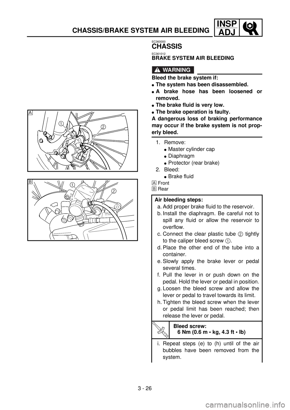
1. Remove:
lMaster cylinder cap
lDiaphragm
lProtector (rear brake)
2. Bleed:
lBrake fluid
Front
õRear
Air bleeding steps:
a. Add proper brake fluid to the reservoir.
b. Install the diaphragm. Be careful not to
spill any fluid or allow the reservoir to
overflow.
c. Connect the clear plastic tube 2 tightly
to the caliper bleed screw 1.
d. Place the other end of the tube into a
container.
e. Slowly apply the brake lever or pedal
several times.
f. Pull the lever in or push down on the
pedal. Hold the lever or pedal in position.
g. Loosen the bleed screw and allow the
lever or pedal to travel towards its limit.
h. Tighten the bleed screw when the lever
or pedal limit has been reached; then
release the lever or pedal.
T R..
Bleed screw:
6 Nm (0.6 m • kg, 4.3 ft • lb)
i. Repeat steps (e) to (h) until of the air
bubbles have been removed from the
system.
õ
Page 287 of 762
INSP
ADJ
PARTIE CYCLE/PURGE DE L’AIR DU SYSTEME DE FREINAGE
FAHRWERK/HYDRAULISCHE BREMSANLAGE ENTLÜFTEN
CHASIS/PURGA DEL AIRE DEL SISTEMA DE FRENOS
FAHRWERK
HYDRAULISCHE BREMSANLAGE
ENTLÜFTEN
WARNUNG
Die Anlage muß entlüftet werden,
wenn:
ldie Anlage zerlegt wurde,
lein Schlauch gelöst oder erneu-
ert wurde,
lder Flüssigkeitsstand sehr nied-
rig ist,
ldie Anlage nicht einwandfrei
funktioniert.
Eine nicht korrekt durchgeführte
Entlüftung kann zur Verminderung
der Bremsleistung führen.
1. Demontieren:
lAusgleichsbehälterdeckel
lMembran
lProtektor (Hinterradbremse)
2. Entlüften:
lBremsflüssigkeit
Vorn
õHinten
Arbeitsschritte
a. Ausgleichsbehälter mit der
empfohlenen Bremsflüssigkeit
befüllen. Darauf achten, daß
keine Flüssigkeit verschüttet
wird und der Ausgleichsbehäl-
ter nicht überläuft.
b. Membran einsetzen.
c. Durchsichtigen Kunststoff-
schlauch 2 fest auf Entlüf-
tungsschraube 1 aufstecken.
d. Freies Schlauchende in Auf-
fangbehälter führen.
e. Hand- bzw. Fußbremshebel
mehrmals langsam betätigen.
f. Handbremshebel ziehen bzw.
Fußbremshebel drücken und
in dieser Stellung halten.
g. Entlüftungsschraube lockern
und Hand- bzw. Fußbrems-
hebel bis zum Anschlag
bewegen.
h. Entlüftungsschraube festzie-
hen, danach Hand- bzw. Fuß-
bremshebel loslassen.
T R..
Entlüftungsschraube
6 Nm (0,6 m • kg)
i. Schritte (e) bis (h) solange
wiederholen, bis sich keine
Luftblasen mehr im Kunst-
stoffschlauch befinden.
PARTIE CYCLE
PURGE DE L’AIR DU SYSTEME
DE FREINAGE
AVERTISSEMENT
Purger le système de freinage si:
lLe système a été démonté.
lUn tuyan de frein a été desserré ou
deposé.
lLe liquide de frein est très bas.
lLe frein fonctionne mal.
Si le système de freinage n’est pas cor-
rectement purgé, cela peut se traduire
par une dangereuse perte d’efficacité
de freinage.
1. Déposer:
lCapuchon de maître-cylindre
lDiaphragme
lProtecteur (frein arrière)
2. Purger:
lLiquide de frein
Avant
õArrière
Etapes de purge de l’air:
a. Ajouter du liquide de frein cor-
rect dans le réservoir.
b. Mettre en place le diaphragme.
Prendre garde à ne pas renverser
ou faire déborder le réservoir.
c. Connecter hermétiquement le
tuyau transparent en matière
plastique 2, à la vis de purge 1
de l’étrier.
d. Mettre l’autre extrémité du tuyau
dans un récipient.
e. Actionner légèrement plusieurs
fois le levier ou la pédale de
frein.
f. Appuyer sur le levier ou la
pédale de frein et le maintenir
dans cette position.
g. Desserrer la vis de purge et lais-
ser le levier ou la pédale s’enfon-
cer sur toute sa course.
h. Resserrer la vis de purge quand
le levier ou la pédale a atteint sa
limite.
Relâcher ensuite le levier ou la
pédale.
T R..
Vis de purge:
6 Nm
(0,6 m • kg, 4,3 ft • lb)
i. Refaire le opérations (e) à (h)
jusqu’à l’élimination totale des
bulles d’air du système.
3 - 26
CHASIS
PURGA DEL AIRE DEL SISTEMA
DE FRENOS
ADVERTENCIA
Purgue el sistema de frenos cuando:
lSe haya desmontado el sistema.
lSe haya aflojado o extraído un tubo
del freno.
lEl líquido de frenos esté muy bajo.
lFalle el sistema de frenado.
Si el sistema de frenos no se purga
adecuadamente, puede ocurrir una
pérdida de la capacidad de frenado
muy peligrosa.
1. Extraer:
lTapa del cilindro principal
lDiafragma
lProtector (freno trasero)
2. Purgar:
lLíquido de frenos
Delantero
õTrasero
Pasos de purga del aire:
a. Añada el líquido de frenos reco-
mendado en el depósito.
b. Instale el diafragma. Tenga cui-
dado en no derramar líquido de
frenos y permitir que se des-
borde el depósito.
c. Conecte un tubo de plástico lim-
pio 2 bien ajustado al tornillo
de purga del caliper 1.
d. Conecte el otro extremo del tubo
al recipiente.
e. Vaya accionando despacio la
palanca o el pedal del freno
varias veces.
f. Levante la palanca o empuje el
pedal. Mantenga la palanca o el
pedal en esa posición.
g. Afloje el tornillo de purga y deje
que la palanca o el pedal llegue
hasta su límite.
h. Apriete el tornillo de purga
cuando la palanca o el pedal
hayan alcanzado su límite; des-
pués, suelte la palanca o el pedal.
T R..
Tornillo de purga:
6 Nm
(0,6 m • kg, 4,3 ft • lb)
i. Repita los pasos (e) hasta (h)
hasta que se hayan extraído
todas las burbujas de aire del sis-
tema.
Page 288 of 762
3 - 27
INSP
ADJ
FRONT BRAKE ADJUSTMENT
3. Install:
lProtector (rear brake)
lDiaphragm
lMaster cylinder cap
NOTE:
If bleeding is difficult, it may be necessary to
let the brake fluid system stabilize for a few
hours. Repeat the bleeding procedure when
the tiny bubbles in the system have disap-
peared.
j. Add brake fluid to the level line on the
reservoir.
WARNING
Check the operation of the brake after
bleeding the brake system.
EC362040
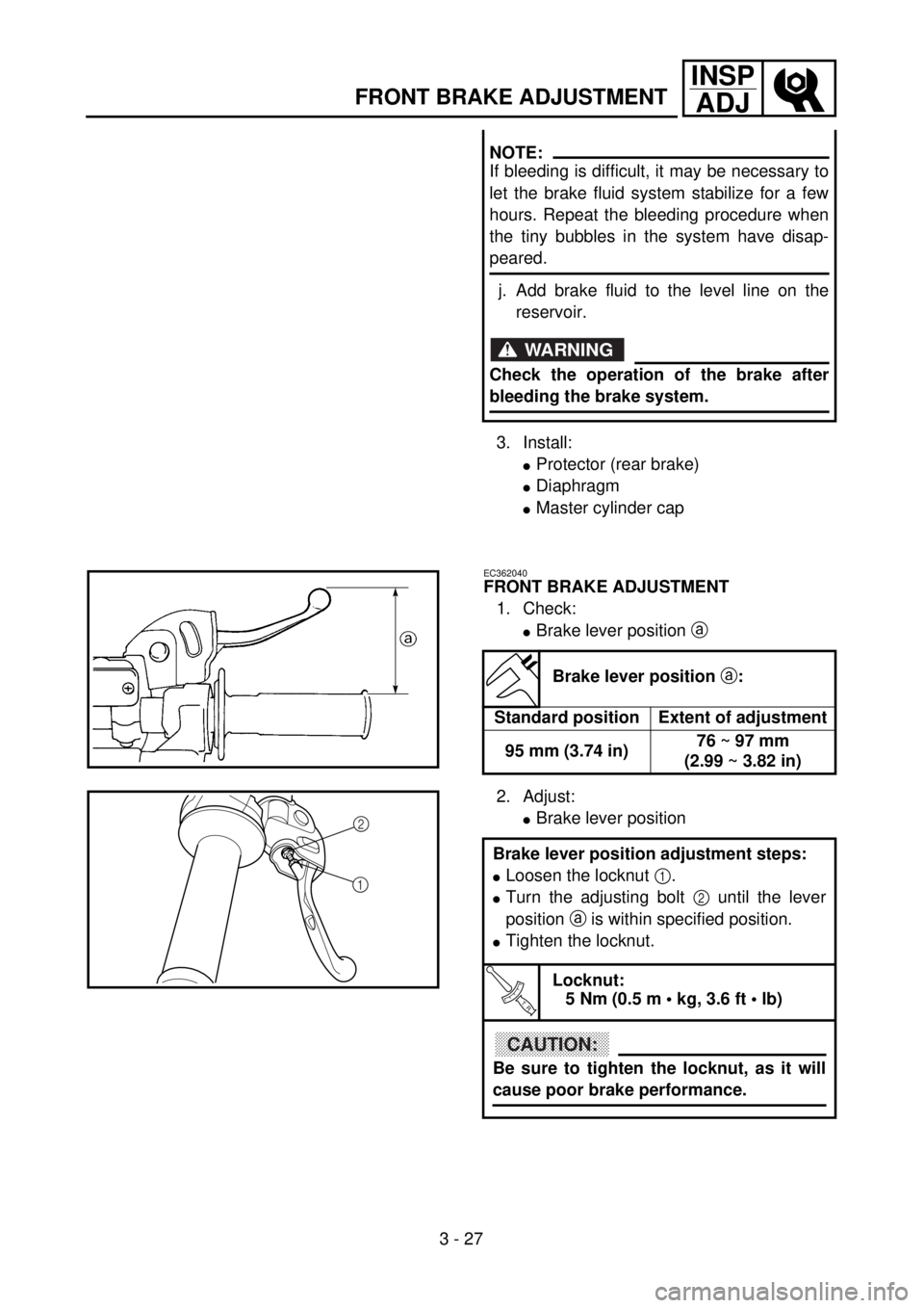
FRONT BRAKE ADJUSTMENT
1. Check:
lBrake lever position a
Brake lever position a:
Standard position Extent of adjustment
95 mm (3.74 in)76 ~ 97 mm
(2.99 ~ 3.82 in)
2. Adjust:
lBrake lever position
Brake lever position adjustment steps:
lLoosen the locknut 1.
lTurn the adjusting bolt 2 until the lever
position a is within specified position.
lTighten the locknut.
T R..
Locknut:
5 Nm (0.5 m • kg, 3.6 ft • lb)
CAUTION:
Be sure to tighten the locknut, as it will
cause poor brake performance.
2
1
Page 289 of 762
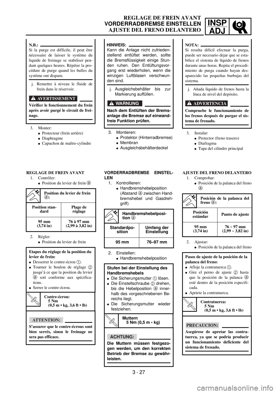
INSP
ADJ
REGLAGE DE FREIN AVANT
VORDERRADBREMSE EINSTELLEN
AJUSTE DEL FRENO DELANTERO
3. Montieren:
lProtektor (Hinterradbremse)
lMembran
lAusgleichsbehälterdeckel
HINWEIS:
Kann die Anlage nicht zufrieden-
stellend entlüftet werden, sollte
die Bremsflüssigkeit einige Stun-
den ruhen. Den Entlüftungsvor-
gang erst wiederholen, wenn die
winzigen Luftblasen verschwun-
den sind.
j. Ausgleichsbehälter bis zur
Markierung auffüllen.
WARNUNG
Nach dem Entlüften der Brems-
anlage die Bremse auf einwand-
freie Funktion prüfen.
VORDERRADBREMSE EINSTEL-
LEN
1. Kontrollieren:
lHandbremshebelposition
(Abstand a zwischen Hand-
bremshebel und Gasdreh-
griff)
2. Einstellen:
lHandbremshebelposition
Handbremshebelposi-
tion a
Standardpo-
sitionUmfang der
Einstellung
95 mm 76–97 mm
Stufen bei der Einstellung des
Handbremshebels
lDie Sicherungsmutter 1 lösen.
lDie Einstellschraube 2 drehen,
bis die Hebelposition a inner-
halb des vorgeschriebenen Be-
reichs liegt.
lDie Sicherungsmutter wieder
festziehen.
T R..
Muttern
5 Nm (0,5 m • kg)
ACHTUNG:
Die Muttern müssen festgezo-
gen werden, um den korrekten
Betrieb der Bremse zu gewähr-
leisten.
3. Monter:
lProtecteur (frein arrière)
lDiaphragme
lCapuchon de maître-cylindre
N.B.:
Si la purge est difficile, il peut être
nécessaire de laisser le système du
liquide de freinage se stabiliser pen-
dant quelques heures. Répéter la pro-
cédure de purge quand les bulles du
système ont disparu.
j. Remettre à niveau le fluide de
frein dans le réservoir.
AVERTISSEMENT
Vérifier le fonctionnement du frein
après avoir purgé le circuit de frei-
nage.
REGLAGE DE FREIN AVANT
1. Contrôler:
lPosition du levier de frein a
2. Régler:
lPosition du levier de frein
Position du levier de frein
a:
Position stan-
dardPlage de
réglage
95 mm
(3,74 in)76 à 97 mm
(2,99 à 3,82 in)
Etapes du réglage de la position du
levier de frein:
lDesserrer le contre-écrou 1.
lTourner le boulon de réglage 2
jusqu’à ce que la position du levier
a soit conforme aux spécifica-
tions.
lSerrer le contre-écrou.
T R..
Contre-écrou:
5 Nm
(0,5 m • kg, 3,6 ft • lb)
ATTENTION:
S’assurer que le contre-écrous sont
bien serrés, sinon le freinage ne
sera pas efficace.
3 - 27
3. Instalar:
lProtector (freno trasero)
lDiafragma
lTapa del cilindro principal
NOTA:
Si resulta difícil efectuar la purga,
puede ser necesario dejar que se esta-
bilice el sistema de líquido de frenos
durante unas horas. Repita el procedi-
miento de purga cuando hayan des-
aparecido las pequeñas burbujas del
sistema.
j. Añada líquido de frenos hasta la
línea de nivel del depósito.
ADVERTENCIA
Compruebe le funcionamiento de
los frenos después de purgar el sis-
tema de frenado.
AJUSTE DEL FRENO DELANTERO
1. Comprobar:
lPosición de la palanca del freno
a
2. Ajustar:
lPosición de la palanca del freno
Posición de la palanca del
freno a:
Posición
estándar Punto de ajuste
95 mm
(3,74 in)76 ~ 97 mm
(2,99 ~ 3,82 in)
Pasos de ajuste de la posición de la
palanca del freno:
lAfloje la contratuerca 1.
lGire el perno de ajuste 2 hasta
que la posición de la palanca a
esté dentro de la posición especifi-
cada.
lApriete la contratuerca.
T R..
Contratuerca:
5 Nm
(0,5 m • kg, 3,6 ft • lb)
PRECAUCION:
Asegúrese de apretar las contra-
tuerca, ya que se podría producir
un funcionamiento deficiente del
sistema de frenado.
Page 290 of 762
3 - 28
INSP
ADJREAR BRAKE ADJUSTMENT/
FRONT BRAKE PAD INSPECTION AND REPLACEMENT
EC364002
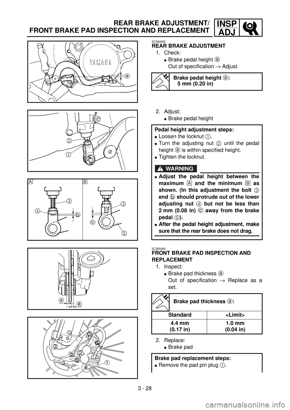
REAR BRAKE ADJUSTMENT
1. Check:
lBrake pedal height a
Out of specification ® Adjust.
Brake pedal height a:
5 mm (0.20 in)
2. Adjust:
lBrake pedal height
Pedal height adjustment steps:
lLoosen the locknut 1.
lTurn the adjusting nut 2 until the pedal
height a is within specified height.
lTighten the locknut.
WARNING
lAdjust the pedal height between the
maximum and the minimum õ as
shown. (In this adjustment the bolt 3
end b should protrude out of the lower
adjusting nut 4 but not be less than
2 mm (0.08 in) c away from the brake
pedal 5).
lAfter the pedal height adjustment, make
sure that the rear brake does not drag.
EC365080
FRONT BRAKE PAD INSPECTION AND
REPLACEMENT
1. Inspect:
lBrake pad thickness a
Out of specification ® Replace as a
set.
2. Replace:
lBrake pad
Brake pad thickness a:
Standard
4.4 mm
(0.17 in)1.0 mm
(0.04 in)
Brake pad replacement steps:
lRemove the pad pin plug 1.