sensor YAMAHA WR 426F 2001 Notices Demploi (in French)
[x] Cancel search | Manufacturer: YAMAHA, Model Year: 2001, Model line: WR 426F, Model: YAMAHA WR 426F 2001Pages: 762, PDF Size: 62.36 MB
Page 24 of 762

CHAPTER 5
CHASSIS
FRONT WHEEL AND REAR WHEEL
...... 5-1
FRONT BRAKE AND REAR BRAKE
..... 5-11
FRONT FORK
......................................... 5-28
HANDLEBAR
.......................................... 5-41
STEERING
.............................................. 5-46
SWINGARM
............................................ 5-52
REAR SHOCK ABSORBER
................... 5-59
CHAPTER 6
ELECTRICAL
ELECTRICAL COMPONENTS AND
WIRING DIAGRAM
................................... 6-1
MAP-CONTROLLED CDI UNIT
................ 6-2
IGNITION SYSTEM
................................... 6-3
TPS (THROTTLE POSITION SENSOR)
SYSTEM
.................................................... 6-7
LIGHTING SYSTEM
................................ 6-11
CHAPTER 7
TUNING
ENGINE
..................................................... 7-1
CHASSIS
................................................. 7-11
Page 25 of 762

KAPITEL 5
FAHRWERK
VORDER- UND HINTERRAD .... 5-1
VORDER- UND
HINTERRADBREMSE ............. 5-11
TELESKOPGABEL .................. 5-28
LENKER ................................... 5-41
LENKKOPF .............................. 5-46
SCHWINGE .............................. 5-52
FEDERBEIN ............................. 5-59
KAPITEL 6
ELEKTRISCHE
ANLAGE
ELEKTRISCHE BAUTEILE UND
SCHALTPLAN ............................ 6-1
KENNFELDGESTEUERTES
CDI-ZÜNDSYSTEM .................... 6-2
ZÜNDANLAGE ........................... 6-3
TPS-SYSTEM (DROSSELKLAP-
PEN-POSITIONSSENSOR) ....... 6-7
LICHTANLAGE ........................ 6-11
KAPITEL 7
ABSTIMMUNG
MOTOR ....................................... 7-1
FAHRGESTELL ....................... 7-11
CHAPITRE 5
PARTIE CYCLE
ROUE AVANT ET ROUE
ARRIERE ........................................ 5-1
FREIN AVANT ET FREIN
ARRIERE ...................................... 5-11
FOURCHE AVANT ..................... 5-28
GUIDON ........................................ 5-41
DIRECTION ................................. 5-46
BRAS OSCILLANT ..................... 5-52
AMORTISSEUR ARRIERE ....... 5-59
CHAPITRE 6
PARTIE
ELECTRIQUE
COMPOSANTS ELECTRIQUES
ET SCHEMA DE CABLAGE ....... 6-1
BLOC CDI CONTROLE PAR
MICROPROCESSEUR ................. 6-2
SYSTEME D’ALLUMAGE .......... 6-3
SYSTEME TPS
(CAPTEUR DU PAPILLON
D’ACCELERATION) .................... 6-7
SYSTEME D’ECLAIRAGE ........ 6-11
CHAPITRE 7
MISES AU POINT
MOTEUR ........................................ 7-1
PARTIE CYCLE .......................... 7-11
CABÍTULO 5
CHASIS
RUEDA DELANTERA Y
RUEDA TRASERA ........................ 5-1
FRENO DELANTERO Y
FRENO TRASERO ...................... 5-11
HORQUILLA DELANTERA ..... 5-28
MANILLAR .................................. 5-41
DIRECCIÓN ................................. 5-46
PALANCA OSCILANTE ............ 5-52
AMORTIGUADOR
TRASERO ..................................... 5-59
CABÍTULO 6
SISTEMA
ELÉCTRICO
COMPONENTES DEL SISTEMA
ELÉCTRICO Y DIAGRAMA
DE CABLES .................................... 6-1
UNIDAD CDI CONTROLADA
POR MAPA ..................................... 6-2
SISTEMA DE ENCENDIDO ........ 6-3
SISTEMA TPS
(SENSOR DE POSICIÓN
DEL ACELERADOR) ................... 6-7
SISTEMA DE ALUMBRADO .... 6-11
CABÍTULO 7
PUESTA A PUNTO
MOTOR ........................................... 7-1
CHASIS ......................................... 7-11
Page 218 of 762
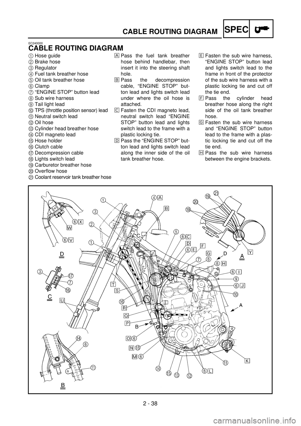
2 - 38
SPEC
CABLE ROUTING DIAGRAM
EC240000
CABLE ROUTING DIAGRAM
1
Hose guide
2
Brake hose
3
Regulator
4
Fuel tank breather hose
5
Oil tank breather hose
6
Clamp
7
“ENGINE STOP” button lead
8
Sub wire harness
9
Tail light lead
0
TPS (throttle position sensor) lead
A
Neutral switch lead
B
Oil hose
C
Cylinder head breather hose
D
CDI magneto lead
E
Hose holder
F
Clutch cable
G
Decompression cable
H
Lights switch lead
I
Carburetor breather hose
J
Overflow hose
K
Coolant reservoir tank breather hose
Pass the fuel tank breather
hose behind handlebar, then
insert it into the steering shaft
hole.
õ
Pass the decompression
cable, “ENGINE STOP” but-
ton lead and lights switch lead
under where the oil hose is
attached.
‚
Fasten the CDI magneto lead,
neutral switch lead “ENGINE
STOP” button lead and lights
switch lead to the frame with a
plastic locking tie.
ë
Pass the “ENGINE STOP” but-
ton lead and lights switch lead
along the inner side of the oil
tank breather hose.
ä
Fasten the sub wire harness,
“ENGINE STOP” button lead
and lights switch lead to the
frame in front of the protector
of the sub wire harness with a
plastic locking tie and cut off
the tie end.
ì
Pass the cylinder head
breather hose along the right
side of the oil tank breather
hose.
í
Fasten the sub wire harness
and “ENGINE STOP” button
lead to the frame with a plas-
tic locking tie and cut off the
tie end.
î
Pass the sub wire harness
between the engine brackets.
Page 219 of 762

SPEC
2 - 38
CHEMINEMENT DES CABLES
KABELFÜHRUNG
DIAGRAMA DE RUTA DE CABLES
KABELFÜHRUNG
1
Kabelführung
2
Bremsschlauch
3
Regler
4
Kraftstofftank-Belüftungsschlauch
5
Öltank-Belüftungsschlauch
6
Kabelbinder
7
Motorstoppschalter-Kabel
8
Nebenkabelsatz
9
Rücklicht
0
Drosselklappensensor-Kabel
A
Leerlaufschalter-Kabel
BÖlschlauch
CZylinderkopf-Entlüftungsschlauch
DCDI-Schwungradmagnetzünder-Ka-
bel
ESchlauchhalterung
FKupplungszug
GDekompressionszug
HLichtschalterleitung
IVergaser-Entlüftungsschlauch
JAuslaufschutzschlauch
KKühlmittelausgleichstank-Lüftungs-
schlauch
Den Kraftstofftank-Belüftungs-
schlauch zwischen Lenker und
Zugstrebe führen und das Ende durch
die Bohrung im Nummerschild führen.
õDen Dekompressionszug hinter dem
Öltank-Belüftungsschlauch und über
das Öltankrohr führen.
‚Das CDI-Schwungradmagnetzünder-
Kabel, Leerlaufschalter-Kabel und
Motorstoppschalter-Kabel mit wieder-
verwenden. Kabelbinder am Rahmen
befestigen.
ëDas Motorstoppschalter-Kabel hinter
dem Öltank-Belüftungsschlauch füh-
ren.
äDen Nebenkabelbaum das Motor-
stoppschalter-Kabel und das Licht-
schalterkabel mit. Kabelbinder am
Rahmen befestigen und das Binde-
rende abschneiden.
ìDen Zylinderkopf-Entlüftungsschlauch
rechts vom Öltank-Belüftungs-
schlauch führen.
íDen Nebenkabelbaum und die Motor-
stoppschalterleitung mit einem Kabel-
binder am Rahmen befestigen und
das überstehende Kabelbinderende
abschneiden.
îDen Nebenkabelsatz zwischen den
Motorlagern hindurchführen.
CHEMINEMENT DES
CABLES
1Guide de flexible
2Tuyau de frein
3Régulateur
4Reniflard de réservoir d’essence
5Reniflard de réservoir d’huile
6Bride
7Fil de bouton d’arrêt du moteur
“ENGINE STOP”
8Faisceau de fils secondaires
9Fil de feux arrière
0Fil de TPS (copteur du papillon d’accélé-
ration)
AFil de contacteur de point mort
BFlexible d’huile
CReniflard de culasse
DFil de magnéto CDI
ESupport de flexible
FCâble d’embrayage
GCâble du décompresseur
HFil de commutateur de feux
IReniflard de carburateur
JFlexible de trop-plein
KFlexible de reniflard du réservoir de
liquide de refroidissement
Faire passer le flexible de reniflard du
réservoir d’essence derrière le guidon,
puis l’insérer dans le trou de l’axe de la
colonne de direction.
õFaire passer le câble de décompression, le
fil de bouton d’arrêt du moteur “ENGINE
STOP” et le fil de commutateur de feux
sous l’endroit où le flexible d’huile est
attaché.
‚Attacher le fil de magnéto CDI, le fil de
commutateur de point mort, le fil du bou-
ton d’arrêt du moteur “ENGINE STOP”
et le fil de commutateur de feux au cadre
à l’aide d’une attache en plastique.
ëFaire passer le fil de bouton d’arrêt du
moteur “ENGINE STOP” et le fil de com-
mutateur de feux le long du côté intérieur
du flexible de reniflard du réservoir
d’huile.
äAttacher le faisceau de fils secondaires, le
fil de bouton d’arrêt du moteur “ENGINE
STOP” et le fil de commutateur de feux
au cadre devant la protection du faisceau
de fils secondaires à l’aide d’une attache
en plastique et couper l’extrémité de
l’attach.
ìFaire passer le reniflard de culasse le long
du côté droit du reniflard du réservoir
d’huile.
íAttacher le faisceau de fils secondaires et
le fil de bouton d’arrêt du moteur
“ENGINE STOP” au cadre à l’aide d’une
attache en plastique et couper l’extrémité
de celle-ci.
îFaire passer le faisceau de fils secondaire
par les supports du moteur.
DIAGRAMA DE RUTA DE
CABLES
1Guía del tubo
2Tubo del freno
3Regulador
4Tubo respiradero del depósito de combus-
tible
5Tubo respiradero del depósito de aceite
6Abrazadera
7Cable del botón de parada del motor
“ENGINE STOP”
8Sub-cableado
9Cable de la luz trasera
0Cable TPS (sensor de posición del acele-
rador)
ACable del interruptor de punto muerto
BTubo de aceite
CTubo respiradero de la culata
DCable del magneto CDI
ESoporte del tubo
FCable del embrague
GCable de descompresión
HCable del interruptor de las luces
ITubo respiradero del carburador
JTubo de desbordamiento
KTubo respiradero del depósito de reserva
del refrigerante
Pasar el tubo respiradero del depósito de
combustible por detrás del manillar y des-
pués insertarlo en del orificio del eje de la
dirección.
õPasar el cable de descompresión, el cable
del botón de parada del motor “ENGINE
STOP” y el cable del interruptor de las
luces por debajo de la zona de colocación
del tubo de aceite.
‚Sujetar el cable del magneto CDI, el cable
del interruptor de punto muerto, el cable
del botón de parada del motor “ENGINE
STOP” y el cable del interruptor de las
luces al bastidor mediante una conexión
plástica de cierre.
ëPasar el cable del botón de parada del
motor “ENGINE STOP” y el cable del
interruptor de las luces por la parte interna
lateral del tubo respiradero del depósito
de aceite.
äSujetar el sub-cableado, el cable del botón
de parada del motor “ENGINE STOP” y
el cable del interruptor de las luces al bas-
tidor delante del protector del sub-
cableado con una conexión plástica de
cierre y corte el extremo de la conexión
plástica.
ìPasar el tubo respiradero de la culata por
el lado derecho del tubo respiradero del
depósito de aceite.
íSujetar el sub-cableado y el cable del
botón de parada del motor “ENGINE
STOP” al bastidor con una conexión plás-
tica de cierre y corte el extremo de la
conexión plástica.
îPasar el sub-cableado entre las ménsulas
del motor.
Page 351 of 762
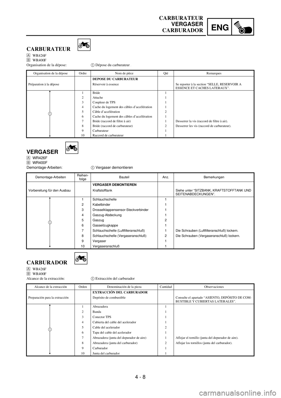
4 - 8
ENG
CARBURATEUR
VERGASER
CARBURADOR
VERGASER
WR426F
õWR400F
Demontage-Arbeiten:1 Vergaser demontieren
Demontage-ArbeitenReihen-
folgeBauteil Anz. Bemerkungen
VERGASER DEMONTIEREN
Vorbereitung für den Ausbau Kraftstofftank Siehe unter “SITZBANK, KRAFTSTOFFTANK UND
SEITENABDECKUNGEN”.
1 Schlauchschelle 1
2 Kabelbinder 1
3 Drosselklappensensor-Steckverbinder 1
4 Gaszug-Abdeckung 1
5 Gaszug 2
6 Gasseilzugkappe 1
7 Schlauchschelle (Luftfilteranschluß) 1 Die Schrauben (Luftfilteranschluß) lockern.
8 Schlauchschelle (Vergaseranschluß) 2 Die Schrauben (Vergaseranschluß) lockern.
9 Vergaser 1
10 Vergaseranschluß 1
1
CARBURATEUR
WR426F
õWR400F
Organisation de la dépose:1 Dépose du carburateur
.
Organisation de la dépose Ordre Nom de pièce Qté Remarques
DEPOSE DU CARBURATEUR
Préparation à la dépose Réservoir à essence Se reporter à la section “SELLE, RESERVOIR A
ESSENCE ET CACHES LATERAUX”.
1 Bride 1
2 Attache 1
3 Coupleur de TPS 1
4 Cache du logement des câbles d’accélération 1
5 Câble d’accélération 2
6 Cache du logement des câbles d’accélération 1
7 Bride (raccord de filtre à air) 1 Desserrer la vis (raccord de filtre à air).
8 Bride (raccord de carburateur) 2 Desserrer les vis (raccord de carburateur).
9 Carburateur 1
10 Raccord de carburateur 1
1
CARBURADOR
WR426F
õWR400F
Alcance de la extracción:1 Extracción del carburador
Alcance de la extracción Orden Denominación de la pieza Cantidad Observaciones
EXTRACCIÓN DEL CARBURADOR
Preparación para la extracción Depósito de combustible Consulte el apartado “ASIENTO, DEPÓSITO DE COM-
BUSTIBLE Y CUBIERTAS LATERALES”.
1 Abrazadera 1
2 Banda 1
3 Conector TPS 1
4 Cubierta del cable del acelerador 1
5 Cable del acelerador 2
6 Tapa del cable del acelerador 1
7 Abrazadera (junta del depurador de aire) 1 Aflojar el tornillo (junta del depurador de aire).
8 Abrazadera (junta del carburador) 2 Aflojar los tornillos (junta del carburador).
9 Carburador 1
10 Junta del carburador 1
1
Page 356 of 762
4 - 11
ENGCARBURETOR
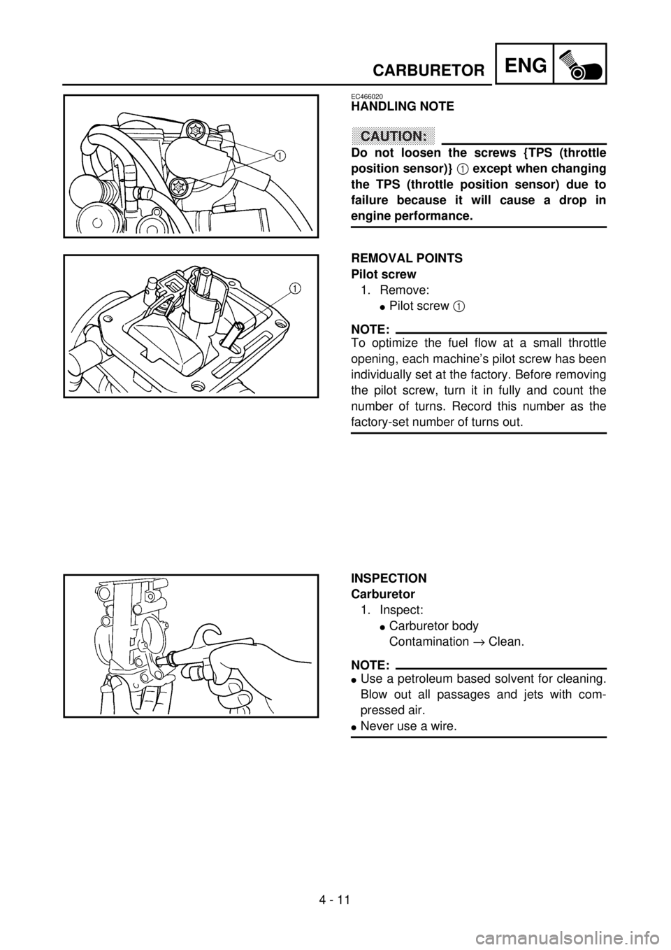
EC466020
HANDLING NOTE
CAUTION:
Do not loosen the screws {TPS (throttle
position sensor)} 1 except when changing
the TPS (throttle position sensor) due to
failure because it will cause a drop in
engine performance.
REMOVAL POINTS
Pilot screw
1. Remove:
lPilot screw 1
NOTE:
To optimize the fuel flow at a small throttle
opening, each machine’s pilot screw has been
individually set at the factory. Before removing
the pilot screw, turn it in fully and count the
number of turns. Record this number as the
factory-set number of turns out.
INSPECTION
Carburetor
1. Inspect:
lCarburetor body
Contamination ® Clean.
NOTE:
lUse a petroleum based solvent for cleaning.
Blow out all passages and jets with com-
pressed air.
lNever use a wire.
Page 357 of 762
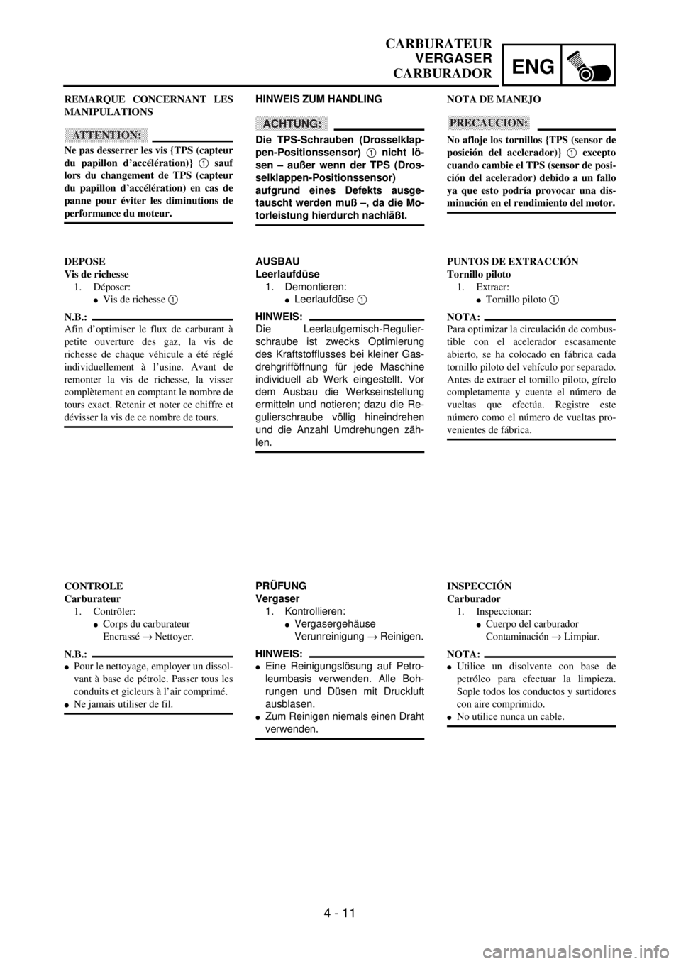
ENG
4 - 11
CARBURATEUR
VERGASER
CARBURADOR
HINWEIS ZUM HANDLING
ACHTUNG:
Die TPS-Schrauben (Drosselklap-
pen-Positionssensor) 1 nicht lö-
sen – außer wenn der TPS (Dros-
selklappen-Positionssensor)
aufgrund eines Defekts ausge-
tauscht werden muß –, da die Mo-
torleistung hierdurch nachläßt.
AUSBAU
Leerlaufdüse
1. Demontieren:
lLeerlaufdüse 1
HINWEIS:
Die Leerlaufgemisch-Regulier-
schraube ist zwecks Optimierung
des Kraftstofflusses bei kleiner Gas-
drehgrifföffnung für jede Maschine
individuell ab Werk eingestellt. Vor
dem Ausbau die Werkseinstellung
ermitteln und notieren; dazu die Re-
gulierschraube völlig hineindrehen
und die Anzahl Umdrehungen zäh-
len.
PRÜFUNG
Vergaser
1. Kontrollieren:
lVergasergehäuse
Verunreinigung ® Reinigen.
HINWEIS:
lEine Reinigungslösung auf Petro-
leumbasis verwenden. Alle Boh-
rungen und Düsen mit Druckluft
ausblasen.
lZum Reinigen niemals einen Draht
verwenden. REMARQUE CONCERNANT LES
MANIPULATIONS
ATTENTION:
Ne pas desserrer les vis {TPS (capteur
du papillon d’accélération)} 1 sauf
lors du changement de TPS (capteur
du papillon d’accélération) en cas de
panne pour éviter les diminutions de
performance du moteur.
DEPOSE
Vis de richesse
1. Déposer:
lVis de richesse 1
N.B.:
Afin d’optimiser le flux de carburant à
petite ouverture des gaz, la vis de
richesse de chaque véhicule a été réglé
individuellement à l’usine. Avant de
remonter la vis de richesse, la visser
complètement en comptant le nombre de
tours exact. Retenir et noter ce chiffre et
dévisser la vis de ce nombre de tours.
CONTROLE
Carburateur
1. Contrôler:
lCorps du carburateur
Encrassé ® Nettoyer.
N.B.:
lPour le nettoyage, employer un dissol-
vant à base de pétrole. Passer tous les
conduits et gicleurs à l’air comprimé.
lNe jamais utiliser de fil.NOTA DE MANEJO
PRECAUCION:
No afloje los tornillos {TPS (sensor de
posición del acelerador)} 1 excepto
cuando cambie el TPS (sensor de posi-
ción del acelerador) debido a un fallo
ya que esto podría provocar una dis-
minución en el rendimiento del motor.
PUNTOS DE EXTRACCIÓN
Tornillo piloto
1. Extraer:
lTornillo piloto 1
NOTA:
Para optimizar la circulación de combus-
tible con el acelerador escasamente
abierto, se ha colocado en fábrica cada
tornillo piloto del vehículo por separado.
Antes de extraer el tornillo piloto, gírelo
completamente y cuente el número de
vueltas que efectúa. Registre este
número como el número de vueltas pro-
venientes de fábrica.
INSPECCIÓN
Carburador
1. Inspeccionar:
lCuerpo del carburador
Contaminación ® Limpiar.
NOTA:
lUtilice un disolvente con base de
petróleo para efectuar la limpieza.
Sople todos los conductos y surtidores
con aire comprimido.
lNo utilice nunca un cable.
Page 366 of 762
4 - 16
ENGCARBURETOR
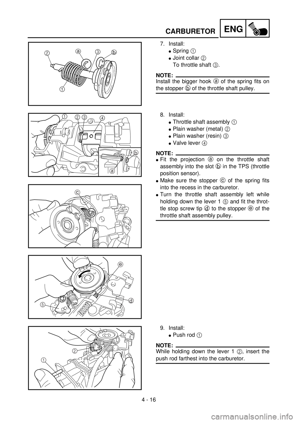
7. Install:
lSpring 1
lJoint collar 2
To throttle shaft 3.
NOTE:
Install the bigger hook a of the spring fits on
the stopper b of the throttle shaft pulley.
8. Install:
lThrottle shaft assembly 1
lPlain washer (metal) 2
lPlain washer (resin) 3
lValve lever 4
NOTE:
lFit the projection a on the throttle shaft
assembly into the slot b in the TPS (throttle
position sensor).
lMake sure the stopper c of the spring fits
into the recess in the carburetor.
lTurn the throttle shaft assembly left while
holding down the lever 1 5 and fit the throt-
tle stop screw tip d to the stopper e of the
throttle shaft assembly pulley.
ab
1
2
3
4
c
e
d
5
9. Install:
lPush rod 1
NOTE:
While holding down the lever 1 2, insert the
push rod farthest into the carburetor.12
Page 367 of 762
ENG
4 - 16
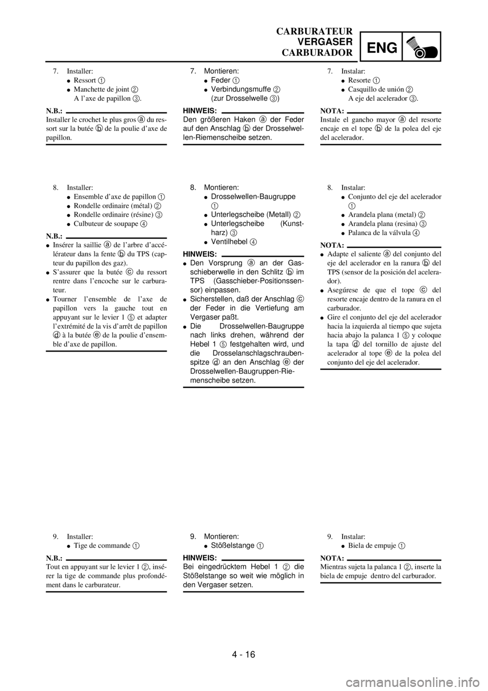
7. Montieren:
lFeder 1
lVerbindungsmuffe 2
(zur Drosselwelle 3)
HINWEIS:
Den größeren Haken a der Feder
auf den Anschlag b der Drosselwel-
len-Riemenscheibe setzen.
8. Montieren:
lDrosselwellen-Baugruppe
1
lUnterlegscheibe (Metall) 2
lUnterlegscheibe (Kunst-
harz) 3
lVentilhebel 4
HINWEIS:
lDen Vorsprung a an der Gas-
schieberwelle in den Schlitz b im
TPS (Gasschieber-Positionssen-
sor) einpassen.
lSicherstellen, daß der Anschlag c
der Feder in die Vertiefung am
Vergaser paßt.
lDie Drosselwellen-Baugruppe
nach links drehen, während der
Hebel 1 5 festgehalten wird, und
die Drosselanschlagschrauben-
spitze d an den Anschlag e der
Drosselwellen-Baugruppen-Rie-
menscheibe setzen.
9. Montieren:
lStößelstange 1
HINWEIS:
Bei eingedrücktem Hebel 1 2 die
Stößelstange so weit wie möglich in
den Vergaser setzen. 7. Installer:
lRessort 1
lManchette de joint 2
A l’axe de papillon 3.
N.B.:
Installer le crochet le plus gros a du res-
sort sur la butée b de la poulie d’axe de
papillon.
8. Installer:
lEnsemble d’axe de papillon 1
lRondelle ordinaire (métal) 2
lRondelle ordinaire (résine) 3
lCulbuteur de soupape 4
N.B.:
lInsérer la saillie a de l’arbre d’accé-
lérateur dans la fente b du TPS (cap-
teur du papillon des gaz).
lS’assurer que la butée c du ressort
rentre dans l’encoche sur le carbura-
teur.
lTourner l’ensemble de l’axe de
papillon vers la gauche tout en
appuyant sur le levier 1 5 et adapter
l’extrémité de la vis d’arrêt de papillon
d à la butée e de la poulie d’ensem-
ble d’axe de papillon.
9. Installer:
lTige de commande 1
N.B.:
Tout en appuyant sur le levier 1 2, insé-
rer la tige de commande plus profondé-
ment dans le carburateur.7. Instalar:
lResorte 1
lCasquillo de unión 2
A eje del acelerador 3.
NOTA:
Instale el gancho mayor a del resorte
encaje en el tope b de la polea del eje
del acelerador.
8. Instalar:
lConjunto del eje del acelerador
1
lArandela plana (metal) 2
lArandela plana (resina) 3
lPalanca de la válvula 4
NOTA:
lAdapte el saliente a del conjunto del
eje del acelerador en la ranura b del
TPS (sensor de la posición del acelera-
dor).
lAsegúrese de que el tope c del
resorte encaje dentro de la ranura en el
carburador.
lGire el conjunto del eje del acelerador
hacia la izquierda al tiempo que sujeta
hacia abajo la palanca 1 5 y coloque
la tapa d del tornillo de ajuste del
acelerador al tope e de la polea del
conjunto del eje del acelerador.
9. Instalar:
lBiela de empuje 1
NOTA:
Mientras sujeta la palanca 1 2, inserte la
biela de empuje dentro del carburador.
CARBURATEUR
VERGASER
CARBURADOR
Page 374 of 762
4 - 20
ENGCARBURETOR
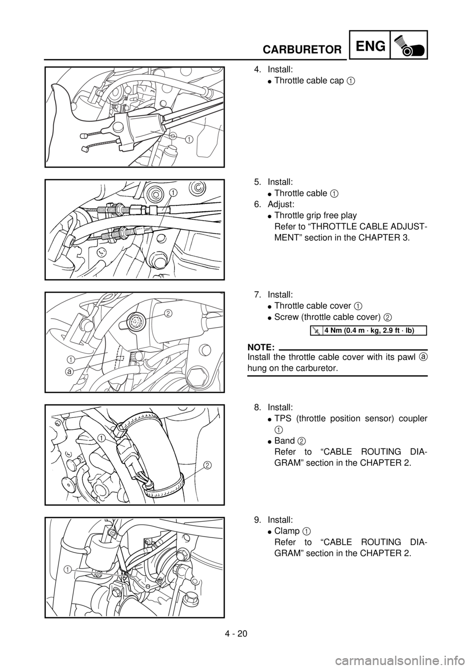
4. Install:
lThrottle cable cap 1
1
5. Install:
lThrottle cable 1
6. Adjust:
lThrottle grip free play
Refer to “THROTTLE CABLE ADJUST-
MENT” section in the CHAPTER 3.
7. Install:
lThrottle cable cover 1
lScrew (throttle cable cover) 2
NOTE:
Install the throttle cable cover with its pawl a
hung on the carburetor.
2
1
a
T R..4 Nm (0.4 m · kg, 2.9 ft · lb)
8. Install:
lTPS (throttle position sensor) coupler
1
lBand 2
Refer to “CABLE ROUTING DIA-
GRAM” section in the CHAPTER 2.
9. Install:
lClamp 1
Refer to “CABLE ROUTING DIA-
GRAM” section in the CHAPTER 2.
1