fork YAMAHA WR 450F 2006 Owner's Manual
[x] Cancel search | Manufacturer: YAMAHA, Model Year: 2006, Model line: WR 450F, Model: YAMAHA WR 450F 2006Pages: 786, PDF Size: 22.49 MB
Page 520 of 786
4 - 102
ENGTRANSMISSION, SHIFT CAM AND SHIFT FORK
EC4H3000
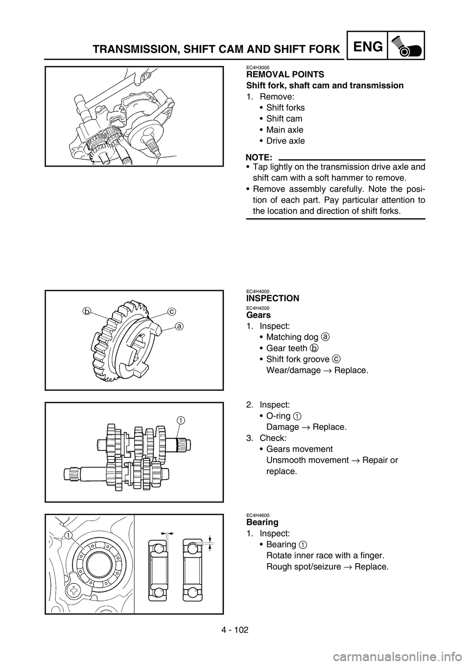
REMOVAL POINTS
Shift fork, shaft cam and transmission
1. Remove:
Shift forks
Shift cam
Main axle
Drive axle
NOTE:
Tap lightly on the transmission drive axle and
shift cam with a soft hammer to remove.
Remove assembly carefully. Note the posi-
tion of each part. Pay particular attention to
the location and direction of shift forks.
EC4H4000
INSPECTION
EC4H4200
Gears
1. Inspect:
Matching dog a
Gear teeth b
Shift fork groove c
Wear/damage → Replace.
2. Inspect:
O-ring 1
Damage → Replace.
3. Check:
Gears movement
Unsmooth movement → Repair or
replace.
EC4H4600
Bearing
1. Inspect:
Bearing 1
Rotate inner race with a finger.
Rough spot/seizure → Replace.
Page 522 of 786
4 - 103
ENGTRANSMISSION, SHIFT CAM AND SHIFT FORK
EC4H4801
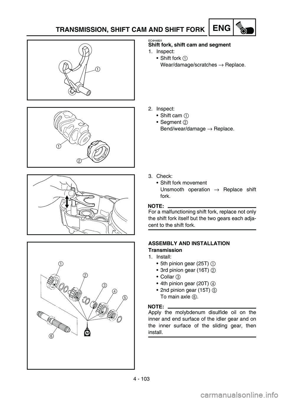
Shift fork, shift cam and segment
1. Inspect:
Shift fork 1
Wear/damage/scratches → Replace.
2. Inspect:
Shift cam 1
Segment 2
Bend/wear/damage → Replace.
3. Check:
Shift fork movement
Unsmooth operation → Replace shift
fork.
NOTE:
For a malfunctioning shift fork, replace not only
the shift fork itself but the two gears each adja-
cent to the shift fork.
ASSEMBLY AND INSTALLATION
Transmission
1. Install:
5th pinion gear (25T) 1
3rd pinion gear (16T) 2
Collar 3
4th pinion gear (20T) 4
2nd pinion gear (15T) 5
To main axle 6.
NOTE:
Apply the molybdenum disulfide oil on the
inner and end surface of the idler gear and on
the inner surface of the sliding gear, then
install.
Page 524 of 786
4 - 104
ENGTRANSMISSION, SHIFT CAM AND SHIFT FORK
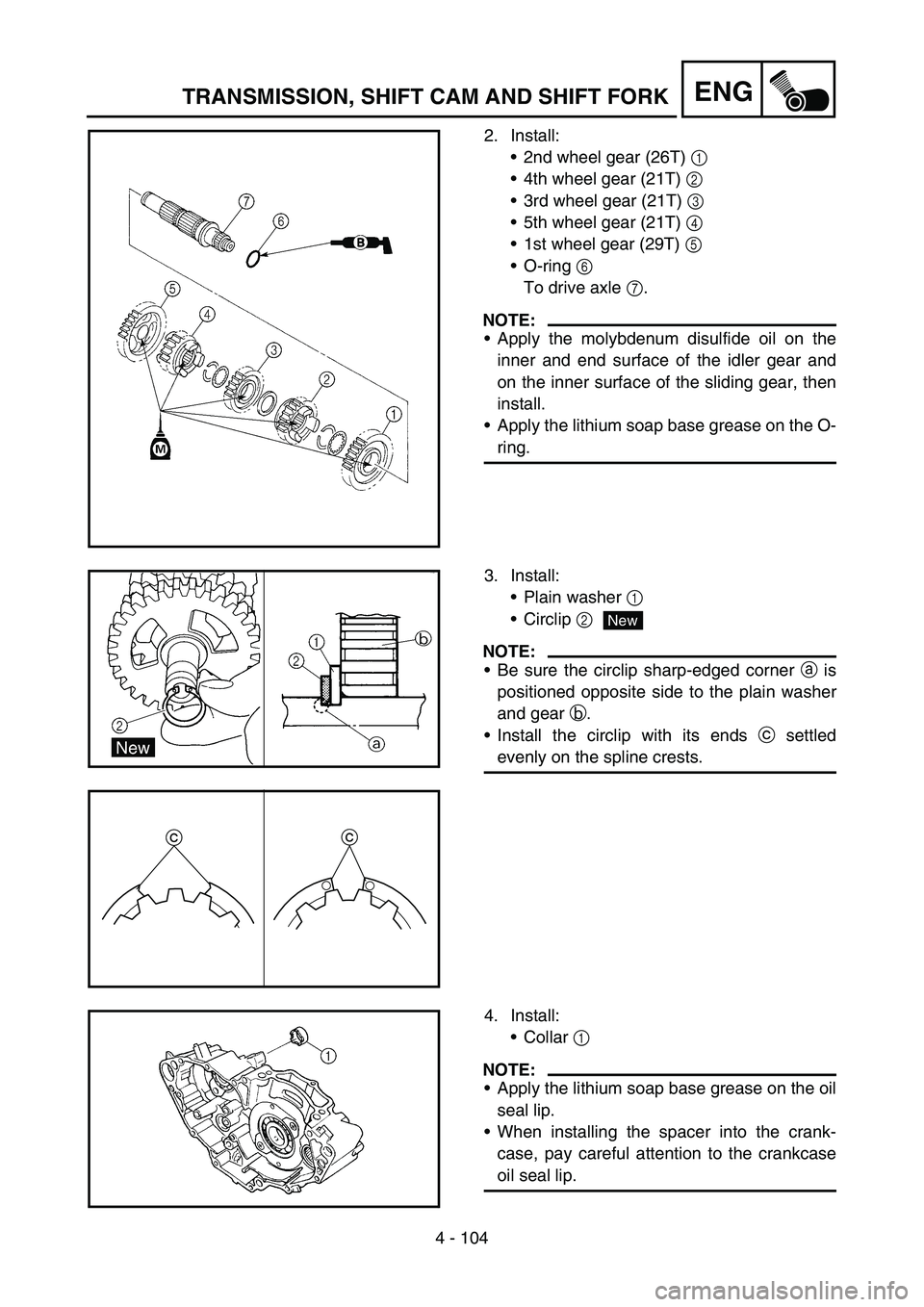
2. Install:
2nd wheel gear (26T) 1
4th wheel gear (21T) 2
3rd wheel gear (21T) 3
5th wheel gear (21T) 4
1st wheel gear (29T) 5
O-ring 6
To drive axle 7.
NOTE:
Apply the molybdenum disulfide oil on the
inner and end surface of the idler gear and
on the inner surface of the sliding gear, then
install.
Apply the lithium soap base grease on the O-
ring.
3. Install:
Plain washer 1
Circlip 2
NOTE:
Be sure the circlip sharp-edged corner a is
positioned opposite side to the plain washer
and gear b.
Install the circlip with its ends c settled
evenly on the spline crests.
cc
New
4. Install:
Collar 1
NOTE:
Apply the lithium soap base grease on the oil
seal lip.
When installing the spacer into the crank-
case, pay careful attention to the crankcase
oil seal lip.
Page 526 of 786
4 - 105
ENGTRANSMISSION, SHIFT CAM AND SHIFT FORK
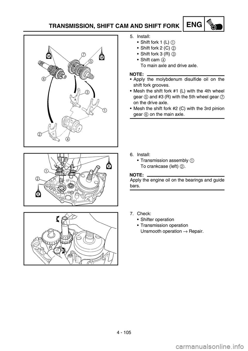
5. Install:
Shift fork 1 (L) 1
Shift fork 2 (C) 2
Shift fork 3 (R) 3
Shift cam 4
To main axle and drive axle.
NOTE:
Apply the molybdenum disulfide oil on the
shift fork grooves.
Mesh the shift fork #1 (L) with the 4th wheel
gear 5 and #3 (R) with the 5th wheel gear 7
on the drive axle.
Mesh the shift fork #2 (C) with the 3rd pinion
gear 6 on the main axle.
6. Install:
Transmission assembly 1
To crankcase (left) 2.
NOTE:
Apply the engine oil on the bearings and guide
bars.
7. Check:
Shifter operation
Transmission operation
Unsmooth operation → Repair.
Page 538 of 786

5 - 6
CHASFRONT WHEEL AND REAR WHEEL
5. Install:
Wheel
NOTE:
Install the brake disc 1 between the brake
pads 2 correctly.
Make sure that the projections a in the
speed sensor fits over the stopper b on the
front fork inner tube.
6. Install:
Wheel axle 1
NOTE:
Apply the lithium soap base grease on the
wheel axle.
7. Install:
Nut (wheel axle) 1
T R..90 Nm (9.0 m · kg, 65 ft · lb)
Page 540 of 786
5 - 7
CHASFRONT WHEEL AND REAR WHEEL
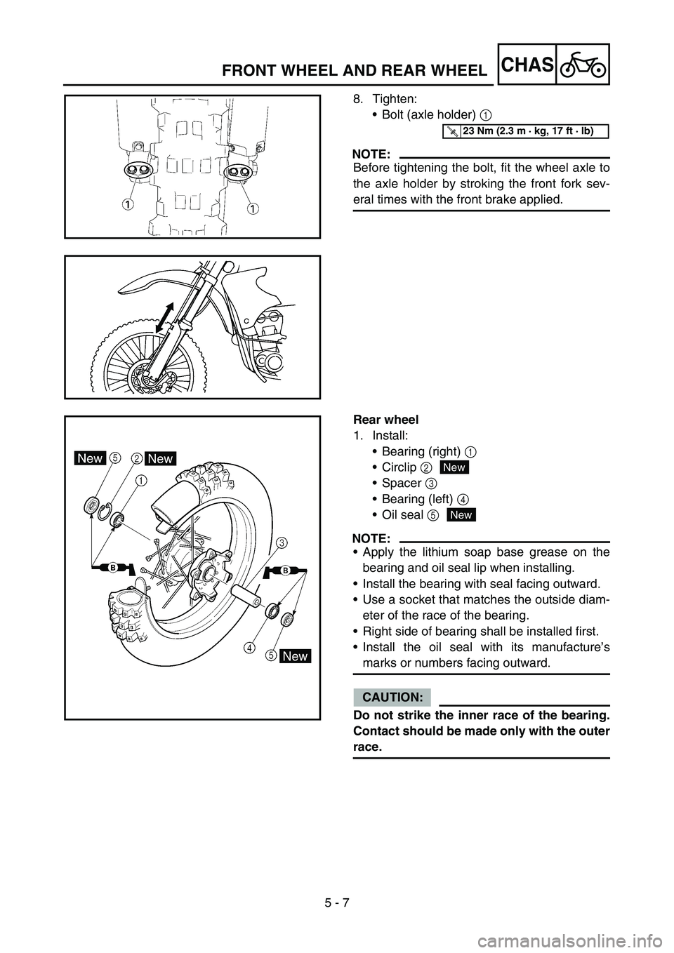
8. Tighten:
Bolt (axle holder) 1
NOTE:
Before tightening the bolt, fit the wheel axle to
the axle holder by stroking the front fork sev-
eral times with the front brake applied.
T R..23 Nm (2.3 m · kg, 17 ft · lb)
Rear wheel
1. Install:
Bearing (right) 1
Circlip 2
Spacer 3
Bearing (left) 4
Oil seal 5
NOTE:
Apply the lithium soap base grease on the
bearing and oil seal lip when installing.
Install the bearing with seal facing outward.
Use a socket that matches the outside diam-
eter of the race of the bearing.
Right side of bearing shall be installed first.
Install the oil seal with its manufacture’s
marks or numbers facing outward.
CAUTION:
Do not strike the inner race of the bearing.
Contact should be made only with the outer
race.
New
New
Page 578 of 786
5 - 26
CHASFRONT FORK
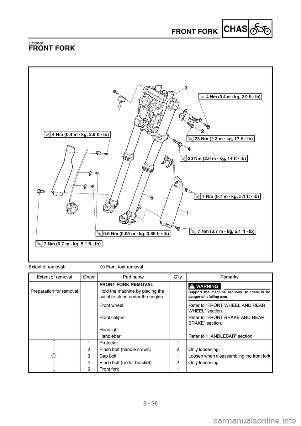
EC550000
FRONT FORK
Extent of removal:
1 Front fork removal
Extent of removal Order Part name Q’ty Remarks
FRONT FORK REMOVAL
WARNING
Support the machine securely so there is nodanger of it falling over.
Preparation for removal Hold the machine by placing the
suitable stand under the engine.
Front wheel Refer to “FRONT WHEEL AND REAR
WHEEL” section.
Front caliper Refer to “FRONT BRAKE AND REAR
BRAKE” section.
Headlight
Handlebar Refer to “HANDLEBAR” section.
1 Protector 1
2 Pinch bolt (handle crown) 2 Only loosening.
3 Cap bolt 1 Loosen when disassembling the front fork.
4 Pinch bolt (under bracket) 2 Only loosening.
5 Front fork 1
1
Page 580 of 786
5 - 27
CHASFRONT FORK
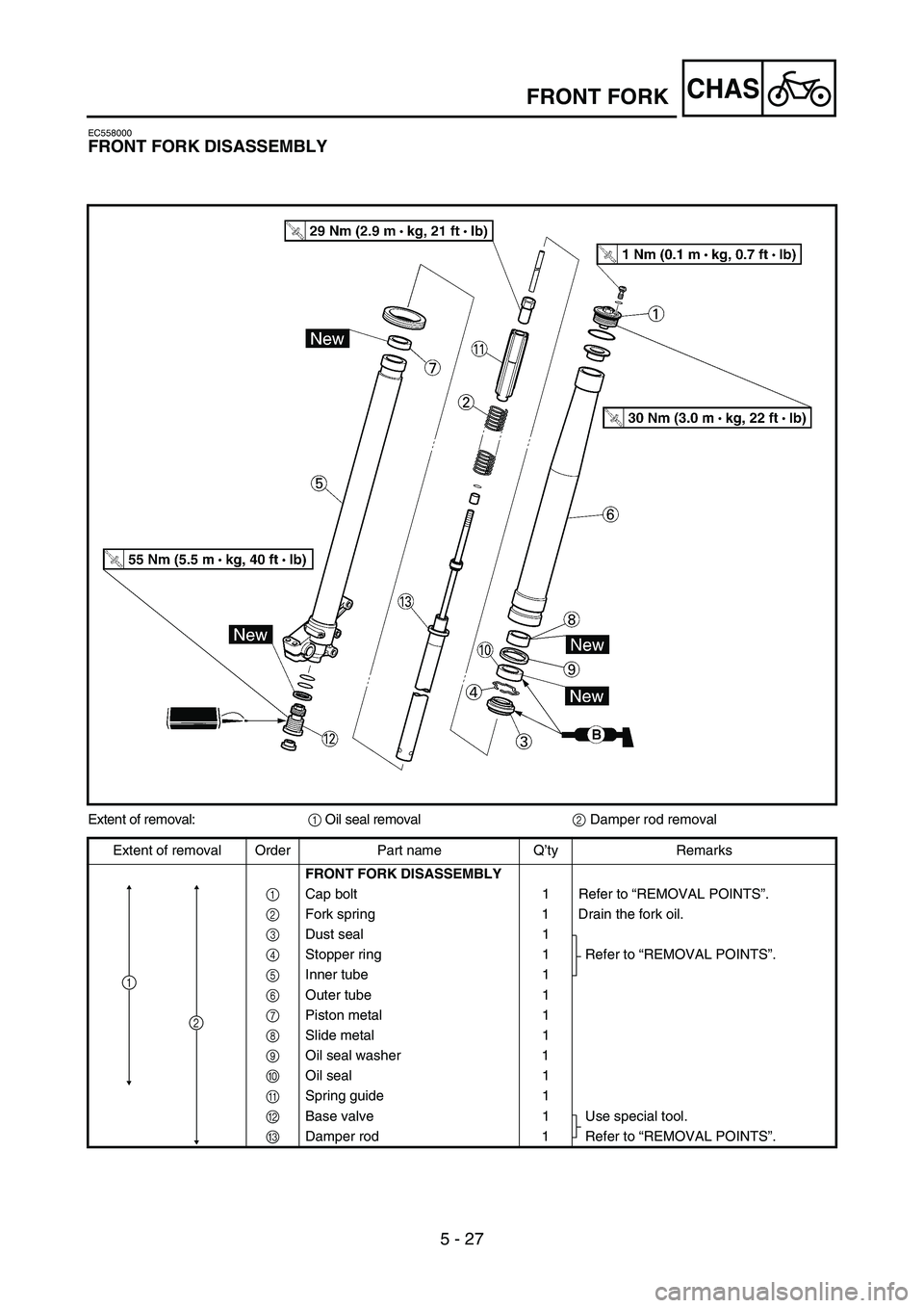
EC558000
FRONT FORK DISASSEMBLY
Extent of removal:
1 Oil seal removal
2 Damper rod removal
Extent of removal Order Part name Q’ty Remarks
FRONT FORK DISASSEMBLY
1 Cap bolt 1 Refer to “REMOVAL POINTS”.
2 Fork spring 1 Drain the fork oil.
3 Dust seal 1
Refer to “REMOVAL POINTS”.
4 Stopper ring 1
5 Inner tube 1
6 Outer tube 1
7 Piston metal 1
8 Slide metal 1
9 Oil seal washer 1
0 Oil seal 1
A Spring guide 1
B Base valve 1 Use special tool.
C Damper rod 1 Refer to “REMOVAL POINTS”.
1
2
Page 582 of 786
5 - 28
CHASFRONT FORK
EC556000
HANDLING NOTE
NOTE:
The front fork requires careful attention. So it is
recommended that the front fork be maintained
at the dealers.
CAUTION:
To prevent an accidental explosion of air,
the following instructions should be
observed:
The front fork with a built-in piston rod
has a very sophisticated internal con-
struction and is particularly sensitive to
foreign material.
Use enough care not to allow any foreign
material to come in when the oil is
replaced or when the front fork is disas-
sembled and reassembled.
Before removing the cap bolts or front
forks, be sure to extract the air from the
air chamber completely.
EC553000
REMOVAL POINTS
EC553150
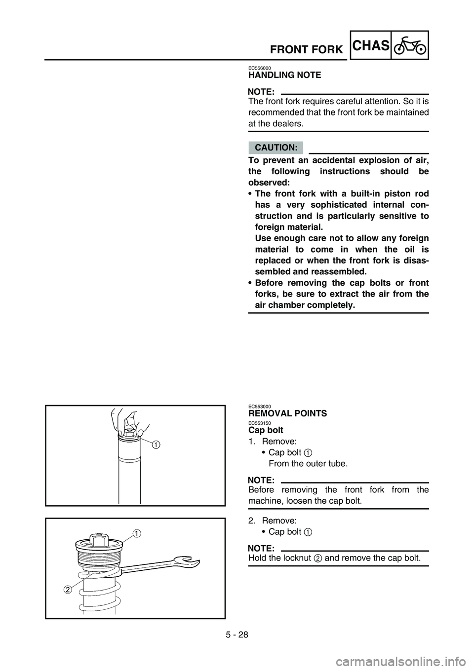
Cap bolt
1. Remove:
Cap bolt 1
From the outer tube.
NOTE:
Before removing the front fork from the
machine, loosen the cap bolt.
2. Remove:
Cap bolt 1
NOTE:
Hold the locknut 2 and remove the cap bolt.
Page 584 of 786
5 - 29
CHAS
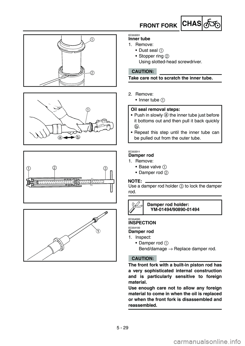
EC553201
Inner tube
1. Remove:
Dust seal 1
Stopper ring 2
Using slotted-head screwdriver.
CAUTION:
Take care not to scratch the inner tube.
2. Remove:
Inner tube 1
Oil seal removal steps:
Push in slowly a the inner tube just before
it bottoms out and then pull it back quickly
b.
Repeat this step until the inner tube can
be pulled out from the outer tube.
EC553311
Damper rod
1. Remove:
Base valve 1
Damper rod 2
NOTE:
Use a damper rod holder 3 to lock the damper
rod.
EC554000
INSPECTION
EC554100
Damper rod
1. Inspect:
Damper rod 1
Bend/damage → Replace damper rod.
CAUTION:
The front fork with a built-in piston rod has
a very sophisticated internal construction
and is particularly sensitive to foreign
material.
Use enough care not to allow any foreign
material to come in when the oil is replaced
or when the front fork is disassembled and
reassembled.
Damper rod holder:
YM-01494/90890-01494
FRONT FORK