light YAMAHA WR 450F 2006 Owner's Manual
[x] Cancel search | Manufacturer: YAMAHA, Model Year: 2006, Model line: WR 450F, Model: YAMAHA WR 450F 2006Pages: 786, PDF Size: 22.49 MB
Page 290 of 786
3 - 47
INSP
ADJ
LUBRICATION
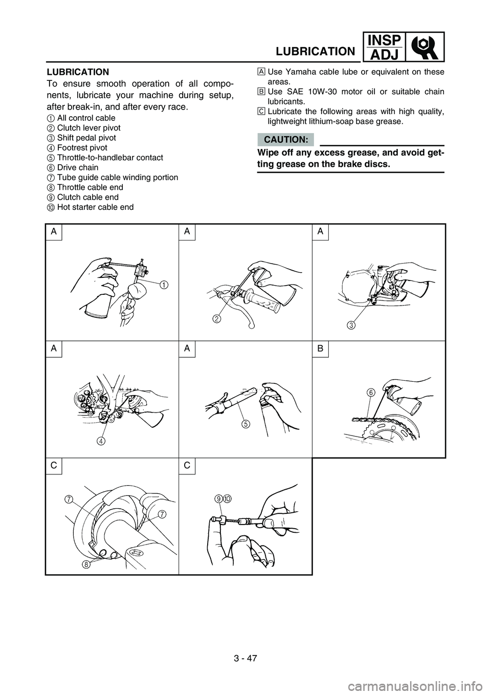
LUBRICATION
To ensure smooth operation of all compo-
nents, lubricate your machine during setup,
after break-in, and after every race.
1All control cable
2Clutch lever pivot
3Shift pedal pivot
4Footrest pivot
5Throttle-to-handlebar contact
6Drive chain
7Tube guide cable winding portion
8Throttle cable end
9Clutch cable end
0Hot starter cable endÈUse Yamaha cable lube or equivalent on these
areas.
ÉUse SAE 10W-30 motor oil or suitable chain
lubricants.
ÊLubricate the following areas with high quality,
lightweight lithium-soap base grease.
CAUTION:
Wipe off any excess grease, and avoid get-
ting grease on the brake discs.
AAA
AA
B
CC
Page 292 of 786

3 - 48
INSP
ADJ
ELECTRICAL/SPARK PLUG INSPECTION
EC370000
ELECTRICAL
EC371001
SPARK PLUG INSPECTION
1. Remove:
Spark plug
2. Inspect:
Electrode 1
Wear/damage → Replace.
Insulator color 2
Normal condition is a medium to light tan
color.
Distinctly different color → Check the
engine condition.
NOTE:
When the engine runs for many hours at low
speeds, the spark plug insulator will become
sooty, even if the engine and carburetor are in
good operating condition.
3. Measure:
Plug gap a
Use a wire gauge or thickness gauge.
Out of specification → Regap.
Spark plug gap:
0.7 ~ 0.8 mm (0.028 ~ 0.031 in)
4. Clean the plug with a spark plug cleaner if
necessary.
5. Tighten:
Spark plug
NOTE:
Before installing a spark plug, clean the gas-
ket surface and plug surface.
Finger-tighten a the spark plug before torqu-
ing to specification b.
T R..13 Nm (1.3 m · kg, 9.4 ft · lb)
Page 294 of 786

3 - 49
INSP
ADJ
IGNITION TIMING CHECK
IGNITION TIMING CHECK
1. Remove:
Timing plug 1
1
2. Attach:
Timing light
Inductive tachometer
To the ignition coil lead (orange lead 1).
Timing light:
YM-33277-A/90890-03141
1
3. Adjust:
Engine idling speed
Refer to “IDLE SPEED ADJUSTMENT”.
4. Check:
Ignition timing
Visually check the stationary pointer a is
within the firing range b on the rotor.
Incorrect firing range → Check rotor and
pickup assembly.
5. Install:
Timing plug
Page 296 of 786
3 - 50
INSP
ADJ
BATTERY INSPECTION AND CHARGING
WARNING
Batteries generate explosive hydrogen gas
and contain electrolyte which is made of
poisonous and highly caustic sulfuric acid.
Therefore, always follow these preventive
measures:
Wear protective eye gear when handling
or working near batteries.
Charge batteries in a well-ventilated area.
Keep batteries away from fire, sparks or
open flames (e.g., welding equipment,
lighted cigarettes).
DO NOT SMOKE when charging or han-
dling batteries.
KEEP BATTERIES AND ELECTROLYTE
OUT OF REACH OF CHILDREN.
Avoid bodily contact with electrolyte as it
can cause severe burns or permanent eye
injury.
FIRST AID IN CASE OF BODILY CONTACT:
EXTERNAL
Skin — Wash with water.
Eyes — Flush with water for 15 minutes
and get immediate medical attention.
INTERNAL
Drink large quantities of water or milk fol-
lowed with milk of magnesia, beaten egg
or vegetable oil. Get immediate medical
attention.
CAUTION:
Charging time, charging amperage and
charging voltage for an MF battery are dif-
ferent from those of conventional batteries.
The MF battery should be charged as
explained in the charging method illustra-
tions. If the battery is overcharged, the
electrolyte level will drop considerably.
Therefore, take special care when charging
the battery.
BATTERY INSPECTION AND CHARGING
Page 314 of 786
3 - 57
INSP
ADJ
REPLACING THE HEADLIGHT BULBS
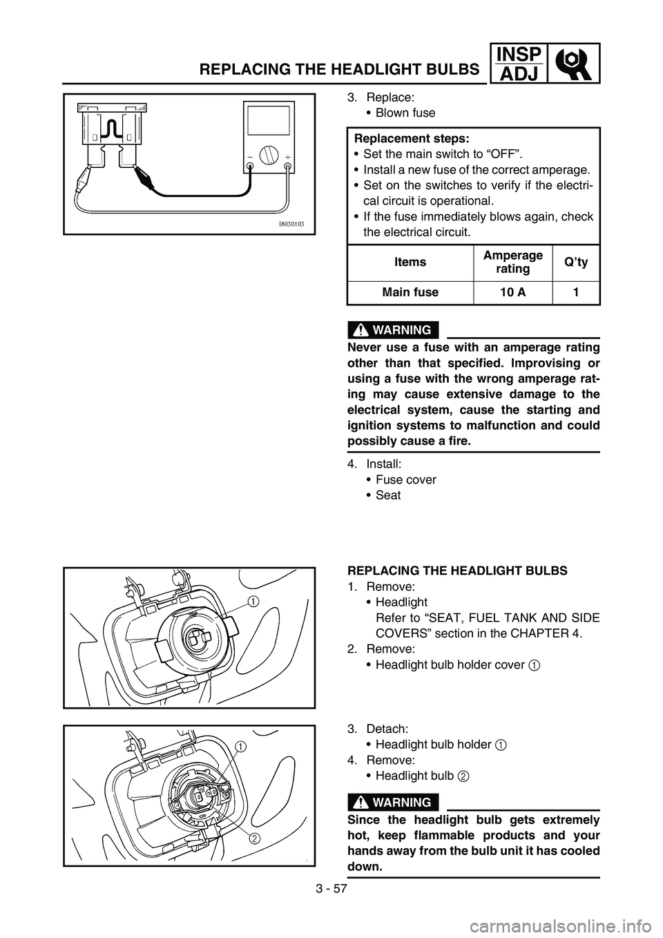
3. Replace:
Blown fuse
WARNING
Never use a fuse with an amperage rating
other than that specified. Improvising or
using a fuse with the wrong amperage rat-
ing may cause extensive damage to the
electrical system, cause the starting and
ignition systems to malfunction and could
possibly cause a fire.
4. Install:
Fuse cover
Seat Replacement steps:
Set the main switch to “OFF”.
Install a new fuse of the correct amperage.
Set on the switches to verify if the electri-
cal circuit is operational.
If the fuse immediately blows again, check
the electrical circuit.
ItemsAmperage
ratingQ’ty
Main fuse 10 A 1
REPLACING THE HEADLIGHT BULBS
1. Remove:
Headlight
Refer to “SEAT, FUEL TANK AND SIDE
COVERS” section in the CHAPTER 4.
2. Remove:
Headlight bulb holder cover 1
3. Detach:
Headlight bulb holder 1
4. Remove:
Headlight bulb 2
WARNING
Since the headlight bulb gets extremely
hot, keep flammable products and your
hands away from the bulb unit it has cooled
down.
Page 316 of 786
3 - 58
INSP
ADJ
ADJUSTING THE HEADLIGHT BEAMS
5. Install:
Headlight bulb
Secure the new headlight bulb with the
headlight bulb holder.
CAUTION:
Avoid touching the glass part of the head-
light bulb to keep it free form oil, otherwise
the transparency of the glass, the life of the
bulb and the luminous flux will be
adversely affected. If the headlight bulb
gets soiled, thoroughly clean it with a cloth
moistened with alcohol or lacquer thinner.
6. Attach:
Headlight bulb holder
7. Install:
Headlight bulb holder cover
8. Install:
Headlight
Refer to “SEAT, FUEL TANK AND SIDE
COVERS” section in the CHAPTER 4.
New
T R..7 Nm (0.7 m · kg, 5.1 ft · lb)
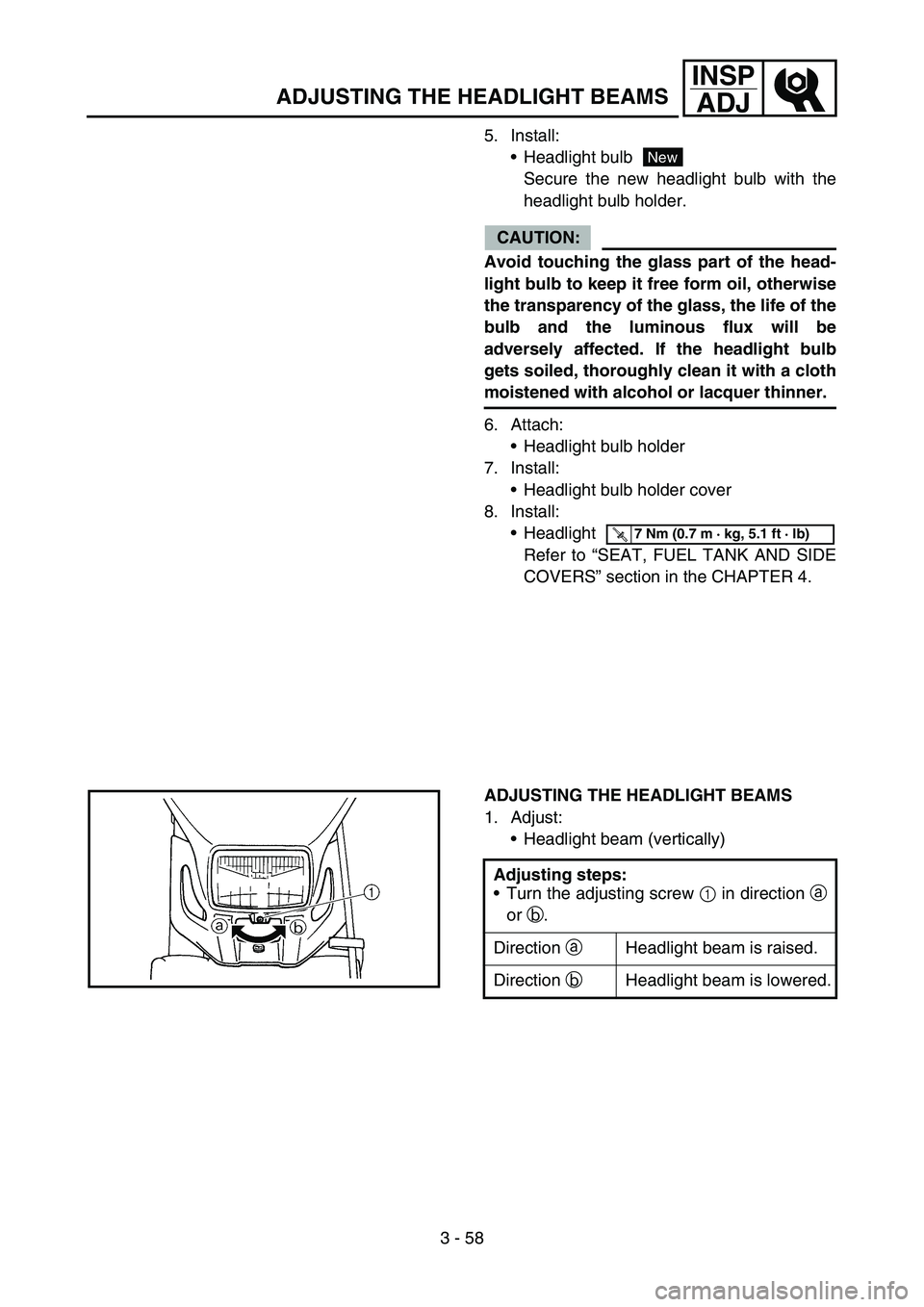
ADJUSTING THE HEADLIGHT BEAMS
1. Adjust:
Headlight beam (vertically)
Adjusting steps:
Turn the adjusting screw 1 in direction a
or b.
Direction a Headlight beam is raised.
Direction bHeadlight beam is lowered.
Page 318 of 786
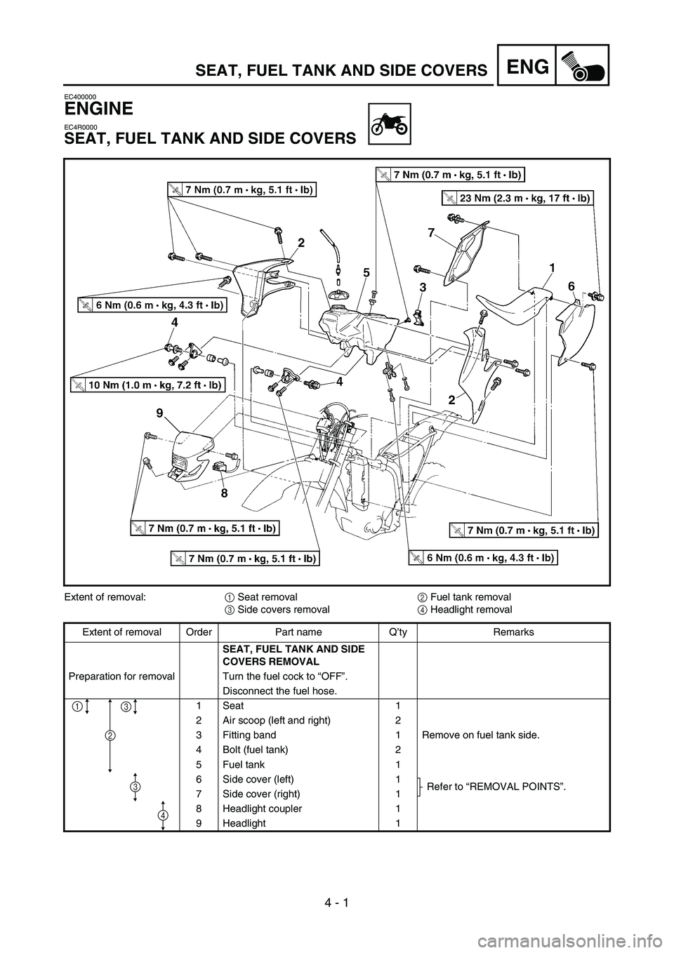
4 - 1
ENG
EC400000
ENGINE
EC4R0000
SEAT, FUEL TANK AND SIDE COVERS
Extent of removal:
1 Seat removal
2 Fuel tank removal
3 Side covers removal
4 Headlight removal
Extent of removal Order Part name Q’ty Remarks
SEAT, FUEL TANK AND SIDE
COVERS REMOVAL
Preparation for removal Turn the fuel cock to “OFF”.
Disconnect the fuel hose.
1Seat 1
2 Air scoop (left and right) 2
3 Fitting band 1 Remove on fuel tank side.
4 Bolt (fuel tank) 2
5 Fuel tank 1
6 Side cover (left) 1
Refer to “REMOVAL POINTS”.
7 Side cover (right) 1
8 Headlight coupler 1
9 Headlight 1
31
2
3
4
SEAT, FUEL TANK AND SIDE COVERS
Page 352 of 786
4 - 18
ENGCARBURETOR
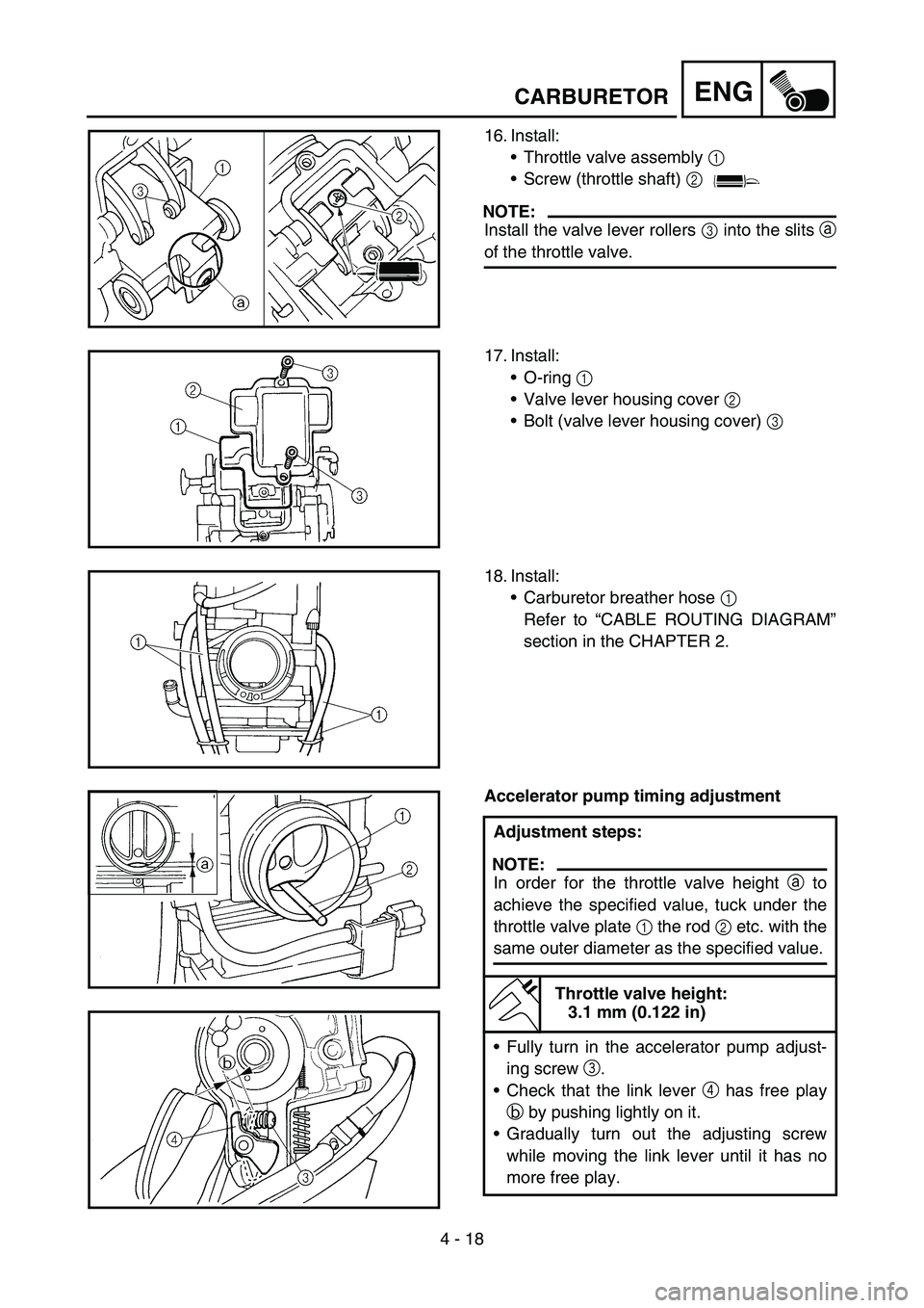
16. Install:
Throttle valve assembly 1
Screw (throttle shaft) 2
NOTE:
Install the valve lever rollers 3 into the slits a
of the throttle valve.
17. Install:
O-ring 1
Valve lever housing cover 2
Bolt (valve lever housing cover) 3
18. Install:
Carburetor breather hose 1
Refer to “CABLE ROUTING DIAGRAM”
section in the CHAPTER 2.
Accelerator pump timing adjustment
Adjustment steps:
NOTE:
In order for the throttle valve height a to
achieve the specified value, tuck under the
throttle valve plate 1 the rod 2 etc. with the
same outer diameter as the specified value.
Throttle valve height:
3.1 mm (0.122 in)
Fully turn in the accelerator pump adjust-
ing screw 3.
Check that the link lever 4 has free play
b by pushing lightly on it.
Gradually turn out the adjusting screw
while moving the link lever until it has no
more free play.
Page 372 of 786

4 - 28
ENGCAMSHAFTS
Decompression system
1. Check:
Decompression system
Checking steps:
Check that the decompressor cam 1
moves smoothly.
Check that the decompressor lever pin 2
projects from the camshaft.
Timing chain tensioner
1. Check:
While pressing the tensioner rod lightly
with fingers, use a thin screwdriver 1
and wind the tensioner rod up fully clock-
wise.
When releasing the screwdriver by press-
ing lightly with fingers, make sure that the
tensioner rod will come out smoothly.
If not, replace the tensioner assembly.
ASSEMBLY AND INSTALLATION
1. Install:
Exhaust camshaft 1
Intake camshaft 2
Installation steps:
Turn the crankshaft counterclockwise until
the “I” mark a on the rotor is aligned with
the stationary pointer b on the crankcase
cover.
NOTE:
Apply the molybdenum disulfide oil on the
camshafts.
Apply the engine oil on the decompression
system.
Page 374 of 786

4 - 29
ENGCAMSHAFTS
Fit the timing chain 3 onto both camshaft
sprockets and install the camshafts on the
cylinder head.
NOTE:
The camshafts should be installed onto the
cylinder head so that the exhaust cam
sprocket punch mark c and the intake cam
sprocket punch mark d align with the sur-
face of the cylinder head.
CAUTION:
Do not turn the crankshaft during the
camshaft installation. Damage or
improper valve timing will result.
Install the clips and camshaft caps 4.
T R..
Bolt (camshaft cap):
10 Nm (1.0 m kg, 7.2 ft lb)
NOTE:
Apply the molybdenum disulfide oil on the
thread of the bolts (camshaft cap) 5.
Tighten the bolts (camshaft cap) in a criss-
cross pattern.
CAUTION:
The bolts (camshaft cap) must be tight-
ened evenly, or damage to the cylinder
head, camshaft caps, and camshaft will
result.
5
4
M
2. Install:
Timing chain tensioner
Installation steps:
While pressing the tensioner rod lightly
with fingers, use a thin screwdriver and
wind the tensioner rod up fully clockwise.